EP0134156A1 - Schmutzfänger zur Verminderung von Sprühwasser - Google Patents
Schmutzfänger zur Verminderung von Sprühwasser Download PDFInfo
- Publication number
- EP0134156A1 EP0134156A1 EP84305699A EP84305699A EP0134156A1 EP 0134156 A1 EP0134156 A1 EP 0134156A1 EP 84305699 A EP84305699 A EP 84305699A EP 84305699 A EP84305699 A EP 84305699A EP 0134156 A1 EP0134156 A1 EP 0134156A1
- Authority
- EP
- European Patent Office
- Prior art keywords
- fingers
- flap
- base
- spray
- base surface
- Prior art date
- Legal status (The legal status is an assumption and is not a legal conclusion. Google has not performed a legal analysis and makes no representation as to the accuracy of the status listed.)
- Granted
Links
Images
Classifications
-
- B—PERFORMING OPERATIONS; TRANSPORTING
- B62—LAND VEHICLES FOR TRAVELLING OTHERWISE THAN ON RAILS
- B62D—MOTOR VEHICLES; TRAILERS
- B62D25/00—Superstructure or monocoque structure sub-units; Parts or details thereof not otherwise provided for
- B62D25/08—Front or rear portions
- B62D25/16—Mud-guards or wings; Wheel cover panels
- B62D25/18—Parts or details thereof, e.g. mudguard flaps
- B62D25/188—Mud-guard flaps for utility vehicles
Definitions
- the present invention relates to improvements . in suppression of spray produced by motor vehicles, and particularly to a mud flap having a spray suppressant surface configuration.
- a motor vehicle for example a large truck
- its wheels pick up fluid from the roadway surface, and such fluid is thrown out by the tires in the form of spray.
- Such fluid, and the splashing and spray resulting therefrom may originate as rainwater, slush from snow, melting ice, mud, and the like.
- this spray When this spray is thrown against a solid surface on the vehicle, it may be deflected or spattered into smaller droplets. As droplets rebound from solid surfaces on the vehicle they are likely to be caught by turbulent air surrounding the vehicle, to be carried in various directions, to be splashed against nearby vehicles, or to be suspended as mist, producing annoying or dangerous conditions of poor visibility in the immediate vicinity of such a vehicle.
- Such splash and spray produced by a large moving vehicle is annoying to vehicles following or alongside, and may impede the vision of the drivers of such vehicles or obscure the other vehicles from the driver of such a large vehicle, often leading to collisions between vehicles.
- the present invention as claimed provides a spray-suppressant material for use on a vehicle to reduce the amount of spray produced by such a vehicle during operation on a wet roadway, comprising:
- a spray-suppressant flap for mounting on a motor vehicle behind the road wheels thereof, comprises:
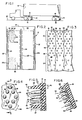
- FIG. 1 a semi-trailer truck 10 is equipped with vertically hanging flaps 12 and horizontally disposed sheets 14 of spray-suppressant material positioned, respectively, behind and above the vehicle wheels 16 to receive and conglomerate spray droplets thrown from the wheels 16 as the vehicle 10 moves in rain or on a wet or slush- covered roadway surface 18.
- the flaps 12 are suspended from suitable hangers provided on the vehicle 10 to hang generally vertically from a position of attachment rearward of the wheels, and to extend close to the ground behind the wheels, ending, for example, within 4 to 6 inches (10-15 cm) above the ground.
- the flaps 12 embodying the present invention may be manufactured of a moldable flexible material such as rubber.
- a moldable flexible material such as rubber.
- granules of reclaimed tire rubber may be vulcanized and molded into the preferred form.
- a suitable flexible and resilient plastics material such as a moldable polyethylene which has an adhesion-resistant surface, is usable for manufacture of the flaps 12.
- a flap 12 in accordance with the present invention preferably has a base sheet 19. As shown at a larger scale in FIG. 2, the flap 12 includes a top margin 20 and lateral margins 22, which have a generally flat surface on the side of the flap 12 which ordinarily faces toward the wheels 16. A lower marginal area 23 is also provided and will be described more fully subsequently.
- a central portion 24, whose outline is indicated by a broken line, may optionally also have a generally flat surface aligned with the space between dual wheels if the vehicle 10 is so equipped. Additionally, raised ribs 25 may be provided in the central portion 24 and in the lateral margins 22, extending generally vertically along the flap 12 and being, for example, generally semicylindrical, with a radius of approximately 3/8 inch (0.9 cm).
- Such a pattern consists preferably of a plurality of diamond-shaped or rhombic groups 30, each including eight fingers 28. Vertically adjacent diamond-shaped groups 30 overlap one another, so that one finger 28 is the end of each of two adjacent groups 30.
- the pattern of the groups 30 may also be thought of as being single fingers 28 located respectively between vertically adjacent hexagonal groups of six fingers 28.
- the adjacent overlapping rhombic groups 30 of fingers 28 define parallel rows 32 of groups 30. Between the rows 32 are channels 34, the groups 30 in each row 32 being staggered longitudinally with respect to the groups 30 in adjacent rows 32 so that the channels 34 are of a zig-zag, rather than straight, configuration, as may be seen in FIGS. 2 and 3.
- the channels 34 thus extend generally vertically along the spray-suppressing area 26 of the flap 12 when it is hanging as shown in FIG. 1, suspended by attachment of the top margin 18 to the semi-trailer truck 10. This orientation of the flap 12 permits the droplets of fluid which has impinged upon the flap 12 to conglomerate and flow generally downward through the channels 34 as indicated by the arrows 36 in FIG. 3.
- each splash-suppressing area 36 a more open pattern of fingers 28 is provided, giving additional area of base surface 29 between the fingers 28.
- Such a lower marginal portion 23 may extend over the bottom 3 inches (7.6 cm) of the flap 12, for example, and is provided in order to enhance shedding of snow or ice where its accumulation is otherwise likely to be heaviest.
- the individual fingers 28 are tapered and generally circular in cross section, and also that they are inclined, although in parallel with one another, at an angle of a few degrees away from being perpendicular to the generally planar base surface 29 of the flap 12 between the fingers 28. Ordinarily this inclination away from the perpendicular is directed downward, so that the central axis 38 of each finger extends at an angle 39 of about 2-15° below the horizontal, when the flap 12 is hanging vertically.
- Each finger 28 is tapered, for example, from a diameter 40 (at its base) of approximately 3/16 of an inch (0.47 cm) to a tip diameter 42 of approximately 1/8 inch (0.3175 cm), with the tip 44 being generally hemispherical.
- Each finger 28 is preferably inclined slightly downward.
- the central axis 38 of each finger is about 8° below the horizontal when the flap 12 is hanging vertically.
- the frustoconical outer surface of each finger defines an angle of about 4° relative to the central axis 38, resulting in the slope of the uppermost surface of each finger preferably being inclined at an angle 46 approximately 12° below horizontal, while the lowermost surface defines an angle 49 of approximately 4° below horizontal.
- Each finger 28 has a height 47 which is preferably at least about two-and-a-half times as great as its diameter 40 at its base, so that it is independently flex-ible along its height, in order to promote shedding of ice and provide additional surface area beyond that of a flat flap of the same size as the flap 12.
- the fingers 28 may preferably be about 1/2 inch (1.27 cm) in height. The flexibility provided in this construction permits the fingers 28 to individually absorb some of the kinetic energy of fluid droplets contributing to reduction of the amount of spray associated with a vehicle 10 equipped with flaps 12.
- the distance 48 between the central axes 38 of the closest adjacent fingers 28 of each group 30 is preferably about 1/4 inch (0.6 cm), giving each diamond-shaped group 30 a width of 1/2 inch (1.27 cm) between the central axes of the corner fingers 28, and each channel 34 preferably has the same width.
- spray droplets impinging upon the spray-suppressant portion 26 of the flap 12 are likely to encounter the surface of one of the fingers 28 initially, or to be splattered against one of the fingers 28 if they first impinge upon a portion of the flat base surface 29. Such droplets will thereafter agglomerate and be blown or drawn by gravity into one of the channels 34 and drain downward along the channels 34 in the direction indicated by the arrows 36. The fluid can then drain from the lower margin 23 of the flap with a reduced likelihood of being suspended in the air as spray or mist.
- the flap 12 When the vehicle 10 is moving forward, creating a considerable amount of relative wind against the forward face of the flap 12, as shown in FIG. 6, the flap 12 is deflected into a rearwardly and downwardly sloping attitude. As a result, the individual fingers 28 are then even more downwardly inclined than when the flap 12 is hanging vertically, presenting more of the surface of the fingers 28 across the predominant paths of movement, indicated by arrows 50, of spray droplets toward the flap 12. Most fluid is deflected or blown toward the base of each finger 28, flowing along the surfaces of the fingers 28 until it reaches the flat base surface 29 and can thereafter drain downwardly through the channels 34.
- the flat central portion 24 and the lateral margins 22 act as wide channels for fluid flow, in the area where there is likely to be least impingement of spray from the tires of a vehicle such as the semi-trailer truck 10 when it is equipped with side by side dual wheels.
- the tapered shape and flexibility of the fingers 28 enable an accumulation of snow or ice to fall free from the fingers 28 of its own weight. Because the fingers 28 are more widely separated, the arrangement of fingers 28 in the lower margin 23 helps to shed snow and ice more efficiently from that portion of the flap 12 where it is otherwise most likely to accumulate.
- the flap 12 is made of a plastics material which has a generally adhesion-resistant surface such as a molded polyethylene and the like there is even less likelihood of snow, slush, ice, or water sticking to the surface and accumulating.
- droplets thrown from the wheels 16 are relatively unobstructed in their paths 50 toward the base surface 29, or impinge upon the surfaces of the fingers 28 at shallow angles. However, when such droplets reach the base surface 29, if they are splattered off it, rebounding onto the surfaces of the fingers 28, they can coalesce and flow along the fingers 28, and then flow downward through the channels 34.
- the spray- or splash-suppressant material of the invention may also be provided as sheets 14 located 5 above the wheels 16, oriented horizontally as shown in FIG. 1, with the fingers 28 of such sheets 14 extending downward and being rearward of vertical, so that the generally rearward direction of the relative wind as the vehicle 10 moves forward aids in directing the flow of fluid rearwardly through the channels 34, for eventual downward flow along the flaps 12.
Landscapes
- Engineering & Computer Science (AREA)
- Chemical & Material Sciences (AREA)
- Combustion & Propulsion (AREA)
- Transportation (AREA)
- Mechanical Engineering (AREA)
- Nozzles (AREA)
Applications Claiming Priority (2)
| Application Number | Priority Date | Filing Date | Title |
|---|---|---|---|
| US526436 | 1983-08-25 | ||
| US06/526,436 US4564204A (en) | 1983-08-25 | 1983-08-25 | Spray-suppressant mud flap |
Publications (2)
| Publication Number | Publication Date |
|---|---|
| EP0134156A1 true EP0134156A1 (de) | 1985-03-13 |
| EP0134156B1 EP0134156B1 (de) | 1989-04-26 |
Family
ID=24097335
Family Applications (1)
| Application Number | Title | Priority Date | Filing Date |
|---|---|---|---|
| EP84305699A Expired EP0134156B1 (de) | 1983-08-25 | 1984-08-22 | Schmutzfänger zur Verminderung von Sprühwasser |
Country Status (4)
| Country | Link |
|---|---|
| US (1) | US4564204A (de) |
| EP (1) | EP0134156B1 (de) |
| CA (1) | CA1228882A (de) |
| DE (1) | DE3477909D1 (de) |
Cited By (10)
| Publication number | Priority date | Publication date | Assignee | Title |
|---|---|---|---|---|
| EP0192344A1 (de) * | 1985-01-23 | 1986-08-27 | Millwood Rubber Company Limited | Schmutzfänger zur Beseitigung Sprühwasserbildung durch Fahrzeugreifen |
| EP0202059A2 (de) * | 1985-05-03 | 1986-11-20 | Patrick F. Sullivan | Sprühwasserbeseitigungsmaterial und Einrichtungen für Strassenfahrzeuge |
| DE3636909A1 (de) * | 1986-05-12 | 1987-11-19 | Josef Lunak | Schmutz- und wasserfaenger fuer kraftfahrzeuge |
| FR2618118A1 (fr) * | 1987-07-16 | 1989-01-20 | Gilardini Spa | Garde-boue pour vehicules automobiles |
| GB2224251A (en) * | 1988-10-28 | 1990-05-02 | Metalplast | Mudflap for road vehicles |
| EP0396873A1 (de) * | 1989-05-10 | 1990-11-14 | KÖVER GMBH & CO. KG Metall- und Kunststoffverarbeitung | Schmutzfangeinrichtung |
| EP0791525A1 (de) * | 1996-02-22 | 1997-08-27 | Team Spatz Limited | Kotflügel mit einer Einrichtung zum Unterdrücken des Spritzens |
| EP0903285A1 (de) * | 1997-09-22 | 1999-03-24 | Fichet S.A. | Schmutzfänger gegen das Spritzen für Strassenfahrzeuge |
| EP2100800A1 (de) | 2008-03-12 | 2009-09-16 | Fichet S.A. | Schmutzfänger-Schutz für Nutzfahrzeuge |
| RU220736U1 (ru) * | 2023-08-16 | 2023-09-29 | Общество С Ограниченной Ответственностью "Производственное Объединение "Автомастер" | Щиток брызгозащитный с функцией гашения туманного облака |
Families Citing this family (12)
| Publication number | Priority date | Publication date | Assignee | Title |
|---|---|---|---|---|
| US4796905A (en) * | 1985-05-03 | 1989-01-10 | Sullivan Patrick F | Spray-suppressant surface configuration |
| GB8511307D0 (en) * | 1985-05-03 | 1985-06-12 | Sullivan P F | Spray suppression material & devices |
| US5375882A (en) * | 1993-01-11 | 1994-12-27 | Koch, Iii; Stanley G. | Mist suppressant panels for a vehicle and a method of suppressing mist |
| US5736472A (en) * | 1995-03-29 | 1998-04-07 | Specialty Adhesive Film Co. | Marking SBR and natural rubber products |
| US5869168A (en) * | 1997-01-10 | 1999-02-09 | Mahn, Jr.; John | Reflective heat activated transfer |
| US7097208B2 (en) * | 2001-08-07 | 2006-08-29 | Richard Maurer | Reinforced splash guard |
| US8146949B2 (en) | 2009-09-02 | 2012-04-03 | Tarun Natwarlal Surti | Mud flap |
| US8616571B2 (en) | 2011-08-23 | 2013-12-31 | Paccar Inc | Vehicle splash guards and adaptors therefor |
| MX2013006298A (es) | 2012-06-05 | 2013-12-16 | Fleet Engineers Inc | Guardafango aerodinamico. |
| US9284000B1 (en) * | 2014-10-17 | 2016-03-15 | Paccar Inc | Vehicle splash guard |
| CN105346603A (zh) * | 2015-11-06 | 2016-02-24 | 黄俊柳 | 一种小汽车挡泥胶板 |
| US11992749B2 (en) | 2022-04-28 | 2024-05-28 | Alexander Rhoades | Portable bowling system and method of use |
Citations (4)
| Publication number | Priority date | Publication date | Assignee | Title |
|---|---|---|---|---|
| GB1101143A (en) * | 1964-01-22 | 1968-01-31 | Karl Dahl Andersen | Improvements in or relating to splashboards |
| GB2084094A (en) * | 1980-09-11 | 1982-04-07 | Typrod Ltd | A spray reducing device for a vehicle |
| DE3102805A1 (de) * | 1981-01-28 | 1982-09-02 | Dunlop Ag, 6450 Hanau | Vorrichtung zur beseitigung stoerender spruehwasserbildung durch fahrzeugreifen |
| US4398739A (en) * | 1980-11-10 | 1983-08-16 | National Rubber Company, Limited | Splash guard |
Family Cites Families (4)
| Publication number | Priority date | Publication date | Assignee | Title |
|---|---|---|---|---|
| US2782053A (en) * | 1955-04-04 | 1957-02-19 | Daniel S Long | Splash guard flap for automotive vehicles |
| US3899192A (en) * | 1974-04-19 | 1975-08-12 | Walter W Reddaway | Splash and spray reducing device for a vehicle |
| GB2050272B (en) * | 1979-05-23 | 1983-05-18 | Goodall Maurice Holdings | Spray-inhibiting means for use on a road vehicle |
| US4382606A (en) * | 1981-02-02 | 1983-05-10 | Lancaster Colony Corporation | Spray controlling system and splash guard for automotive vehicles |
-
1983
- 1983-08-25 US US06/526,436 patent/US4564204A/en not_active Expired - Fee Related
-
1984
- 1984-08-22 EP EP84305699A patent/EP0134156B1/de not_active Expired
- 1984-08-22 DE DE8484305699T patent/DE3477909D1/de not_active Expired
- 1984-08-24 CA CA000461831A patent/CA1228882A/en not_active Expired
Patent Citations (4)
| Publication number | Priority date | Publication date | Assignee | Title |
|---|---|---|---|---|
| GB1101143A (en) * | 1964-01-22 | 1968-01-31 | Karl Dahl Andersen | Improvements in or relating to splashboards |
| GB2084094A (en) * | 1980-09-11 | 1982-04-07 | Typrod Ltd | A spray reducing device for a vehicle |
| US4398739A (en) * | 1980-11-10 | 1983-08-16 | National Rubber Company, Limited | Splash guard |
| DE3102805A1 (de) * | 1981-01-28 | 1982-09-02 | Dunlop Ag, 6450 Hanau | Vorrichtung zur beseitigung stoerender spruehwasserbildung durch fahrzeugreifen |
Cited By (15)
| Publication number | Priority date | Publication date | Assignee | Title |
|---|---|---|---|---|
| EP0192344A1 (de) * | 1985-01-23 | 1986-08-27 | Millwood Rubber Company Limited | Schmutzfänger zur Beseitigung Sprühwasserbildung durch Fahrzeugreifen |
| EP0202059A2 (de) * | 1985-05-03 | 1986-11-20 | Patrick F. Sullivan | Sprühwasserbeseitigungsmaterial und Einrichtungen für Strassenfahrzeuge |
| EP0202059A3 (de) * | 1985-05-03 | 1988-07-13 | Patrick F. Sullivan | Sprühwasserbeseitigungsmaterial und Einrichtungen für Strassenfahrzeuge |
| DE3636909A1 (de) * | 1986-05-12 | 1987-11-19 | Josef Lunak | Schmutz- und wasserfaenger fuer kraftfahrzeuge |
| GB2208160B (en) * | 1987-07-16 | 1991-07-31 | Gilardini Spa | Motor vehicle mudflap |
| GB2208160A (en) * | 1987-07-16 | 1989-03-08 | Gilardini Spa | Spray-suppression device |
| BE1002304A4 (fr) * | 1987-07-16 | 1990-11-27 | Gilardini Spa | Garde-boue pour vehicules automobiles. |
| FR2618118A1 (fr) * | 1987-07-16 | 1989-01-20 | Gilardini Spa | Garde-boue pour vehicules automobiles |
| GB2224251A (en) * | 1988-10-28 | 1990-05-02 | Metalplast | Mudflap for road vehicles |
| EP0396873A1 (de) * | 1989-05-10 | 1990-11-14 | KÖVER GMBH & CO. KG Metall- und Kunststoffverarbeitung | Schmutzfangeinrichtung |
| EP0791525A1 (de) * | 1996-02-22 | 1997-08-27 | Team Spatz Limited | Kotflügel mit einer Einrichtung zum Unterdrücken des Spritzens |
| EP0903285A1 (de) * | 1997-09-22 | 1999-03-24 | Fichet S.A. | Schmutzfänger gegen das Spritzen für Strassenfahrzeuge |
| FR2768688A1 (fr) * | 1997-09-22 | 1999-03-26 | Fichet Sa | Bavette anti-projections pour vehicules routiers |
| EP2100800A1 (de) | 2008-03-12 | 2009-09-16 | Fichet S.A. | Schmutzfänger-Schutz für Nutzfahrzeuge |
| RU220736U1 (ru) * | 2023-08-16 | 2023-09-29 | Общество С Ограниченной Ответственностью "Производственное Объединение "Автомастер" | Щиток брызгозащитный с функцией гашения туманного облака |
Also Published As
| Publication number | Publication date |
|---|---|
| US4564204A (en) | 1986-01-14 |
| EP0134156B1 (de) | 1989-04-26 |
| DE3477909D1 (en) | 1989-06-01 |
| CA1228882A (en) | 1987-11-03 |
Similar Documents
| Publication | Publication Date | Title |
|---|---|---|
| US4564204A (en) | Spray-suppressant mud flap | |
| US4921276A (en) | Spray controlling fender | |
| US7625013B2 (en) | Spray suppression device for vehicles | |
| US5375882A (en) | Mist suppressant panels for a vehicle and a method of suppressing mist | |
| CA1178631A (en) | Spray controlling system and splash guard for automotive vehicles | |
| US4796906A (en) | Spray-suppressant surface configuration | |
| EP1332951B1 (de) | Schmutzfänger für Kraftfahrzeuge | |
| US5080397A (en) | Vehicle tire water spray control system | |
| US5269547A (en) | Spray suppressant apparatus | |
| GB2132148A (en) | Vehicle spray inhibitor | |
| US4796905A (en) | Spray-suppressant surface configuration | |
| US6851717B1 (en) | Mud flap | |
| CA1156293A (en) | Trailer undercarriage fairings | |
| GB2146598A (en) | Spray suppressing panel for motor vehicles | |
| EP1740440A1 (de) | Vorrichtung zur verhinderung von spritzwasser | |
| US4398739A (en) | Splash guard | |
| US4325563A (en) | Vehicle spray reduction | |
| EP0202059A2 (de) | Sprühwasserbeseitigungsmaterial und Einrichtungen für Strassenfahrzeuge | |
| EP0074953B1 (de) | Schmutzfänger für fahrzeug | |
| US5022680A (en) | Spray-suppressant splash guard for vehicles | |
| EP0266228B1 (de) | Spritzbeseitigungsmaterial und Vorrichtungen für Strassenfahrzeuge | |
| EP0077374B1 (de) | Vorrichtung zum verringern von sprüh- und spritzwasser von fahrzeugen | |
| US5205590A (en) | Mudflap for vehicles | |
| GB2084094A (en) | A spray reducing device for a vehicle | |
| EP0149665B1 (de) | Wasserspritzsteuerung für fahrzeugräder |
Legal Events
| Date | Code | Title | Description |
|---|---|---|---|
| PUAI | Public reference made under article 153(3) epc to a published international application that has entered the european phase |
Free format text: ORIGINAL CODE: 0009012 |
|
| AK | Designated contracting states |
Designated state(s): BE CH DE FR GB IT LI NL SE |
|
| 17P | Request for examination filed |
Effective date: 19851112 |
|
| 17Q | First examination report despatched |
Effective date: 19860620 |
|
| D17Q | First examination report despatched (deleted) | ||
| GRAA | (expected) grant |
Free format text: ORIGINAL CODE: 0009210 |
|
| ITF | It: translation for a ep patent filed |
Owner name: BARZANO' E ZANARDO ROMA S.P.A. |
|
| AK | Designated contracting states |
Kind code of ref document: B1 Designated state(s): BE CH DE FR GB IT LI NL SE |
|
| PG25 | Lapsed in a contracting state [announced via postgrant information from national office to epo] |
Ref country code: SE Effective date: 19890426 Ref country code: NL Effective date: 19890426 Ref country code: FR Free format text: LAPSE BECAUSE OF NON-PAYMENT OF DUE FEES Effective date: 19890426 Ref country code: BE Effective date: 19890426 |
|
| REF | Corresponds to: |
Ref document number: 3477909 Country of ref document: DE Date of ref document: 19890601 |
|
| REG | Reference to a national code |
Ref country code: CH Ref legal event code: PL |
|
| PG25 | Lapsed in a contracting state [announced via postgrant information from national office to epo] |
Ref country code: GB Effective date: 19890822 |
|
| ITTA | It: last paid annual fee | ||
| PG25 | Lapsed in a contracting state [announced via postgrant information from national office to epo] |
Ref country code: LI Free format text: LAPSE BECAUSE OF NON-PAYMENT OF DUE FEES Effective date: 19890831 Ref country code: CH Free format text: LAPSE BECAUSE OF NON-PAYMENT OF DUE FEES Effective date: 19890831 |
|
| EN | Fr: translation not filed | ||
| NLV1 | Nl: lapsed or annulled due to failure to fulfill the requirements of art. 29p and 29m of the patents act | ||
| PLBI | Opposition filed |
Free format text: ORIGINAL CODE: 0009260 |
|
| 26 | Opposition filed |
Opponent name: DUNLOP GMBH Effective date: 19900125 |
|
| GBPC | Gb: european patent ceased through non-payment of renewal fee | ||
| PG25 | Lapsed in a contracting state [announced via postgrant information from national office to epo] |
Ref country code: DE Effective date: 19900501 |
|
| RDAG | Patent revoked |
Free format text: ORIGINAL CODE: 0009271 |
|
| STAA | Information on the status of an ep patent application or granted ep patent |
Free format text: STATUS: PATENT REVOKED |
|
| REG | Reference to a national code |
Ref country code: CH Ref legal event code: PL |
|
| 27W | Patent revoked |
Effective date: 19910502 |
|
| PLAB | Opposition data, opponent's data or that of the opponent's representative modified |
Free format text: ORIGINAL CODE: 0009299OPPO |