EP0134017B1 - Microprocessor - controlled positioning system - Google Patents
Microprocessor - controlled positioning system Download PDFInfo
- Publication number
- EP0134017B1 EP0134017B1 EP84109397A EP84109397A EP0134017B1 EP 0134017 B1 EP0134017 B1 EP 0134017B1 EP 84109397 A EP84109397 A EP 84109397A EP 84109397 A EP84109397 A EP 84109397A EP 0134017 B1 EP0134017 B1 EP 0134017B1
- Authority
- EP
- European Patent Office
- Prior art keywords
- displacement
- counter
- line
- movement
- pulses
- Prior art date
- Legal status (The legal status is an assumption and is not a legal conclusion. Google has not performed a legal analysis and makes no representation as to the accuracy of the status listed.)
- Expired
Links
Images

Classifications
-
- B—PERFORMING OPERATIONS; TRANSPORTING
- B41—PRINTING; LINING MACHINES; TYPEWRITERS; STAMPS
- B41J—TYPEWRITERS; SELECTIVE PRINTING MECHANISMS, i.e. MECHANISMS PRINTING OTHERWISE THAN FROM A FORME; CORRECTION OF TYPOGRAPHICAL ERRORS
- B41J11/00—Devices or arrangements of selective printing mechanisms, e.g. ink-jet printers or thermal printers, for supporting or handling copy material in sheet or web form
- B41J11/36—Blanking or long feeds; Feeding to a particular line, e.g. by rotation of platen or feed roller
- B41J11/42—Controlling printing material conveyance for accurate alignment of the printing material with the printhead; Print registering
- B41J11/44—Controlling printing material conveyance for accurate alignment of the printing material with the printhead; Print registering by devices, e.g. programme tape or contact wheel, moved in correspondence with movement of paper-feeding devices, e.g. platen rotation
-
- G—PHYSICS
- G05—CONTROLLING; REGULATING
- G05B—CONTROL OR REGULATING SYSTEMS IN GENERAL; FUNCTIONAL ELEMENTS OF SUCH SYSTEMS; MONITORING OR TESTING ARRANGEMENTS FOR SUCH SYSTEMS OR ELEMENTS
- G05B19/00—Programme-control systems
- G05B19/02—Programme-control systems electric
- G05B19/18—Numerical control [NC], i.e. automatically operating machines, in particular machine tools, e.g. in a manufacturing environment, so as to execute positioning, movement or co-ordinated operations by means of programme data in numerical form
- G05B19/19—Numerical control [NC], i.e. automatically operating machines, in particular machine tools, e.g. in a manufacturing environment, so as to execute positioning, movement or co-ordinated operations by means of programme data in numerical form characterised by positioning or contouring control systems, e.g. to control position from one programmed point to another or to control movement along a programmed continuous path
- G05B19/21—Numerical control [NC], i.e. automatically operating machines, in particular machine tools, e.g. in a manufacturing environment, so as to execute positioning, movement or co-ordinated operations by means of programme data in numerical form characterised by positioning or contouring control systems, e.g. to control position from one programmed point to another or to control movement along a programmed continuous path using an incremental digital measuring device
- G05B19/23—Numerical control [NC], i.e. automatically operating machines, in particular machine tools, e.g. in a manufacturing environment, so as to execute positioning, movement or co-ordinated operations by means of programme data in numerical form characterised by positioning or contouring control systems, e.g. to control position from one programmed point to another or to control movement along a programmed continuous path using an incremental digital measuring device for point-to-point control
-
- G—PHYSICS
- G05—CONTROLLING; REGULATING
- G05B—CONTROL OR REGULATING SYSTEMS IN GENERAL; FUNCTIONAL ELEMENTS OF SUCH SYSTEMS; MONITORING OR TESTING ARRANGEMENTS FOR SUCH SYSTEMS OR ELEMENTS
- G05B2219/00—Program-control systems
- G05B2219/30—Nc systems
- G05B2219/37—Measurements
- G05B2219/37296—Electronic graduation, scale expansion, interpolation
-
- G—PHYSICS
- G05—CONTROLLING; REGULATING
- G05B—CONTROL OR REGULATING SYSTEMS IN GENERAL; FUNCTIONAL ELEMENTS OF SUCH SYSTEMS; MONITORING OR TESTING ARRANGEMENTS FOR SUCH SYSTEMS OR ELEMENTS
- G05B2219/00—Program-control systems
- G05B2219/30—Nc systems
- G05B2219/41—Servomotor, servo controller till figures
- G05B2219/41245—Discrimination of direction
-
- G—PHYSICS
- G05—CONTROLLING; REGULATING
- G05B—CONTROL OR REGULATING SYSTEMS IN GENERAL; FUNCTIONAL ELEMENTS OF SUCH SYSTEMS; MONITORING OR TESTING ARRANGEMENTS FOR SUCH SYSTEMS OR ELEMENTS
- G05B2219/00—Program-control systems
- G05B2219/30—Nc systems
- G05B2219/41—Servomotor, servo controller till figures
- G05B2219/41363—Excess in error, error too large, follow up error
-
- G—PHYSICS
- G05—CONTROLLING; REGULATING
- G05B—CONTROL OR REGULATING SYSTEMS IN GENERAL; FUNCTIONAL ELEMENTS OF SUCH SYSTEMS; MONITORING OR TESTING ARRANGEMENTS FOR SUCH SYSTEMS OR ELEMENTS
- G05B2219/00—Program-control systems
- G05B2219/30—Nc systems
- G05B2219/42—Servomotor, servo controller kind till VSS
- G05B2219/42213—Position overshoot, axis still moves after stop
-
- G—PHYSICS
- G05—CONTROLLING; REGULATING
- G05B—CONTROL OR REGULATING SYSTEMS IN GENERAL; FUNCTIONAL ELEMENTS OF SUCH SYSTEMS; MONITORING OR TESTING ARRANGEMENTS FOR SUCH SYSTEMS OR ELEMENTS
- G05B2219/00—Program-control systems
- G05B2219/30—Nc systems
- G05B2219/45—Nc applications
- G05B2219/45187—Printer
-
- Y—GENERAL TAGGING OF NEW TECHNOLOGICAL DEVELOPMENTS; GENERAL TAGGING OF CROSS-SECTIONAL TECHNOLOGIES SPANNING OVER SEVERAL SECTIONS OF THE IPC; TECHNICAL SUBJECTS COVERED BY FORMER USPC CROSS-REFERENCE ART COLLECTIONS [XRACs] AND DIGESTS
- Y10—TECHNICAL SUBJECTS COVERED BY FORMER USPC
- Y10S—TECHNICAL SUBJECTS COVERED BY FORMER USPC CROSS-REFERENCE ART COLLECTIONS [XRACs] AND DIGESTS
- Y10S400/00—Typewriting machines
- Y10S400/902—Stepping-motor drive for web feed
Definitions
- This invention relates to positioning systems and particularly to such systems that operate in conjunction with a microprocessor or the like.
- the invention is described in connection with a microprocessor-controlled printer carriage using a dc servomotor for positioning a document for the performance of printing lines of data thereon.
- Positioning systems in high speed printers for data processing systems include a paper carriage mechanism driven by a dc motor operated by electronic controls to feed paper one or more print line spaces at a time relative to a print line defined by impression devices such as print hammers.
- the positioning operation consists of accelerating the motor quickly to a selected velocity, maintaining the velocity constant until a selected position is reached, and then decelerating the motor to a desired stop or detent position whereupon the motor is deenergized and printing can commence.
- the electronic controls might include a microprocessor or other controller and a position counter which counts displacement signals generated by an optical or other type encoder device coupled to the motor and/or the carriage drive shaft.
- the optical encode device typically comprises a pair of light sensors and an opaque disk having one or more tracks with uniformly spaced transparent indicia.
- the sensors, the disk, and a light source are arranged so that a pair of motion signals are generated in phase quadrature in response to motor rotation.
- Decode or other circuitry converts the phased signals into a direction signal and displacement pulses where each pulse indicates movement of a fraction of a line space.
- the microprocessor in addition to other control functions involving the motor and other devices associated with the printer, sets the position counter prior to and during motor operation to count the displacement pulses to effect the sequence of motor control operations described.
- the rapid starting and stopping of the carriage mechanism and associated mechanisms produces mechanical perturbations which cause undesired movement of the carriage mechanism, the motor, and the paper.
- the direction and magnitude of this drift movement is essentially variable and irregular.
- the dc motor has no holding torque opposing this undesired movement. Consequently, the motor is periodically operated during printing to reposition the paper.
- the electronics control has ample time to detect the direction and magnitude of the undesired movement and to operate the motor to restore the paper to the desired print line.
- U.S. Patent 4,261,038 issued April 7, 1981 to G. N. Baker et al describes a microprocessor-controlled paper feed mechanism for a printer.
- the microprocessor analyzes relatively slow emitter pulses for start up, normal speed and high speed paper feed and relatively high frequency emitter pulses during deceleration and stopping of the forms.
- DE-A-2845786 relates to a servo motor for a printer or similar device, which under control of a processor is moved from a starting to a stop position.
- the processor includes a control loop consisting of a position counter settable to a nominal value, and a comperator in which said nominal value is deducted from the actual speed value of said motor.
- the function of this device is to reduce overshooting.
- the rate of revolutions of said motor is used to control a speed converter including a second counter.
- a third counter in the control loop receives the output of said comperator for establishing the supply signals for said servo motor.
- This invention provides a control for a dc motor driven positioning system and particularly for a dc motor driven paperfeed mechanism of a printer which corrects for errors in the initial position of the motor caused by undesired carriage movement and thereby provides greater accuracy of the system and particularly in a print line positioning of the paper in a high speed line printer.
- the invention further provides for the above correction and control in a positioning system in which advance and stopping is under microprocessor control but in which movement detection and compensation is independent of microprocessor surveillance and control.
- the invention provides means which detects the amount of undesired carriage movement from a predetermined stop position when the motor is in an uncontrolled state, i.e., is deenergized, and compensates for the resultant positional error during the controlled movement of the motor.
- the motor control comprises first and second counters.
- the first counter is a displacement counter coupled to receive first displacement pulses generated by emitter means coupled to the motor.
- the first displacement pulses produced by the emitter means represent a fine, e.g., 1/4 degree, displacement of the motor both during uncontrolled or undesired movement and controlled operation of the motor.
- the displacement counter counts a predetermined number of the first displacement pulses and produces a second displacement pulse representing a coarse, e.g., one degree, displacement of the motor.
- the second position counter is connected to receive and count the second displacement pulses produced by the displacement counter.
- the second position counter is preset preferably by a microprocessor to count a predetermined number or numbers of second displacement pulses representing a portion of or the total displacement of the motor when operating during its controlled movement operation.
- the displacement counter is an up/down counter and the emitter means includes circuit means for supplying a direction signal and said first displacement pulses.
- the second position counter is also preferably an up/down counter responsive to the direction signals for counting second displacement pulses from the displacement counter in either direction.
- the second position counter is also gated to count the first displacement pulses during detent i.e., while the carriage is at the print line.
- the invention provides means for precision control of the positioning of paper relativeto a print line by determining the amount and direction of error movement of the motor when in its uncontrolled state. Further, the determination of the amount and direction of error movement can be done independently of the microprocessor or other type controller when the motor is in the uncontrolled state and the microprocessor is otherwise occupied with other control functions. Additionally, the compensation is done during the controlled movement of the motor thereby avoiding delay in the positioning operation.
- a forms feed system comprises carriage motors M1 and M2 connected to a transport assembly 10 for a line printer or the like.
- Transport assembly 10 may be -a mechanical assembly including one or more paper feed devices such as paper feed tractors connected to be driven by upper and lower drive shafts rotatably supported on a carriage frame.
- Motors M1 and M2 which are connected in tandem by suitable gearing or pulleys to the upper and lower drive shafts in any well known manner as indicated by broken lines 11 are preferably high speed low inertia permanent magnet dc servo motors connected to be energized in either forward or reverse directions by motor drive circuits such as H drive circuitry 12.
- H-drive circuitry 12 is a well known bridge network comprising power transistors which are switched to connect the motors M1 and M2 to a power source to obtain forward and reverse operation.
- the motion indicating means comprises an optical encoder consisting of an emitter disk 13 and optical transducers 14 and 15.
- Disk 13 is constructed of opaque material having transparent slits 17 arrranged in a single circular track.
- the slits 17 are uniformly spaced. In a preferred embodiment, the angular spacing is one (1) degree. Thus a complete track has three hundred sixty slits 17.
- Disk 13 is coupled to motors M1 and M2 as indicated by broken line 16 and thus moves synchronously therewith.
- Transducers 14 and 15 sense light transmitted through slits 17 by a light source not shown and generate binary motion signals A Emitter and B Emitter.
- Transducers 14 and 15 are angularly spaced and slits 17 made so that motion signals A Emitter and B Emitter are generated in quadrature phase.
- the A Emitter and B Emitter signals are applied to decode circuit 18 which among other things explained hereinafter converts them to purified binary motion signals A, A, B, B and transition signals A EDGE and B EDGE.
- the purified motion signals A and B are square wave binary signals having leading and trailing edges which are ninety electrical or 1/4 mechanical degrees out of phase with each other.
- the span from the leading edge of signal A or B to the next leading edge thereof represents one degree of rotary motion of disk 13.
- FWD forward
- REV reverse
- the leading edge of signal B precedes the leading edge of signal A.
- the motion indicating means also include means for converting the motion signals A Emitter and B Emitter into fine resolution displacement pulses.
- Decode circuit 18 receives the binary motion signals A Emitter and B Emitter from transducers 14 and 15, detects the leading and trailing edges thereof, produces purified binary motion signals A and B and generates a short displacement pulse each time a leading or trailing edge is detected. In the embodiment illustrated, decode circuit 18 supplies 1/4 degree pulses on line 19 to one input of displacement counter 21 and on line 22 to switching circuit 23. Decode circuit 18 also decodes the motion signals A and B and produces the binary direction signal FWD/ REV which is applied on line 20 to a second input of displacement counter 21.
- Fig. 3 shows an edge detection circuit for producing the purified motion signals A, A, and an A EDGE detection pulse which comprises series connected latches 24-27 with an output connected to one input of exclusive OR circuit EOR 28.
- Decode circuit 18 includes a second edge detection circuit for producing purified motion signals B, B, and B EDGE but is not shown since it is identical in structure and operation to the circuit of Fig. 3.
- the edge detection circuit of Fig. 3 operates in the following manner.
- Latch 24 is set by the combination of the leading edge of the A Emitter motion signal from transducer 14 and a specific clock pulse of a series of high resolution clock pulses occurring at selected time periods to activate the latches 24-27 in sequence.
- Latch 25 is set by a second clock pulse and an output from latch 24.
- latch 25 When latch 25 is set, a valid A Emitter has been detected and a purified motion signal A is produced on output line 29.
- Latches 26 and 27 are sequentially set in the same manner by outputs from latches 25 and 26 in combination with third and fourth clock pulses and ultimately producing A EDGE pulse at EOR 28 on line 31. The width of the A EDGE pulse is determined by the time between latch 26 and latch 27 turning on.
- latches 24-27 are reset sequentially in the same order by a series of reset clock pulses.
- Latch 24 is reset by the combination of the trailing edge of A Emitter and the first reset clock pulse.
- Latch 25 is reset by the combination of latch 24 and the second reset clock pulse.
- latch 25 In resetting, latch 25 generates purified motion signal A on output line 30. Latches 26 and 27 then reset in sequence as previously described whereby EOR 28 produces a second A EDGE signal on line 31. The width of the second A EDGE signal is determined by the time interval between latch 26 and latch 27 going off. Thus the circuit of Fig. 3 detects the leading and trailing edges of the A Emitter signal.
- a specific type of decode circuit 18, as shown in Fig. 2, comprises forward decode circuits 1f4f and reverse decode circuits 1R-4R.
- the outputs of forward decode circuits 1 F-4F are fed through OR circuit 32 to one input of the OR circuit 33 and to the set input S of direction latch 34.
- the outputs of reverse decode circuits 1R-4R are connected through OR circuit 35 to the second input of OR 33 and the reset input R of direction latch 34.
- the A and B EDGE signals and the motion signals A, A, B, and B generated by the edge detection circuits as in Fig. 3 are decoded by decode circuits 1 F-4F or 1R-4R to actuate OR 33 which generates 1/4 degree pulses on line 19.
- a 1/4 degree pulse of a short duration is generated by OR 33 on line 19 by the combination of A EDGE, B and A being decoded by decode circuit 1F.
- the combination of A EDGE, B, and A produces a short duration pulse from OR 33 in response to a decode output from decode circuit 4R.
- FWD/REV signals are generated on line 20 from the N output of direction latch 34 in response to the sequence in which binary signals A and B from transducers 14 and 15 and the EDGE signals are produced.
- a EDGE, B, and A cause decode circuit 1F to set direction latch 34 producing a FWD signal on line 20.
- direction latch 34 remains set as a result of the signal from decode circuit 2F through OR circuit 32 to the S input.
- a REV signal is produced on line 20 by direction latch 34 when reset by signal from decode circuit 1R in response to the combination of inputs B EDGE, A, and B.
- Direction latch 34 remains reset by decode circuit 2R if A EDGE, B, and A follow.
- decode circuit 18 is a frequency multiplier which as seen in Fig. 4 provides fine resolution displacement pulses 22 for each transition of signal A and B.
- decode circuit 18 produces 1440 1/4 degree displacement pulses for every complete revolution of disk 13 thereby providing precise position control within a movement of one or more line spaces or fractions thereof.
- the motion indicating means in accordance with this invention also includes means for producing coarse resolution displacement pulses which are generated during motion of disk 13 and which represent motion indicative of a larger fraction of a line space.
- This function is provided by the displacement counter 21 designed to count a predetermined number of fine resolution displacement pulses during extended bidirectional motion of disk 13 and generating a short duration displacement pulse indicating a larger increment of movement each time the predetermined number count is reached.
- displacement counter 21 counts 1/4 degree displacement pulses received on line 19 and supplies 1 degree displacement pulses on line 36 to switching circuit 23.
- displacement counter 21 is a 4-bit bidirectional counter having an output 37 connected to decode circuits 38 and 39.
- the outputs of decode circuits 38 and 39 are connected through OR circuit 40 to the reset input R of displacement counter 21 by line 41 and by line 36 to the AND circuit 42 of switching circuit 23.
- Displacement counter 21 is incremented by 1/ 4 degree pulses on line 19 with a FWD direction signal present on line 20.
- Displacement counter 21 is reset to zero by a 1 degree pulse on line 41 from decode circuit 39 each time a four count is reached.
- Displacement counter 21 is decremented by 1/4 pulses on line 19 when a REV signal is present on line 20.
- Displacement counter 21 is reset to zero by a 1 degree pulse on line 41 from decode circuit 38 each time a twelve count is reached.
- Motors M1 and M2 are operated to feed a continuous print medium in increments of one or more line spaces and then stop for printing. Each feed operation is performed in accordance with a speed profile in which motors M1 and M2 are accelerated rapidly to a desired velocity. The motors are then operated to maintain the velocity essentially constant. After a predetermined displacement relative to the start position and in advance of the final stop position motors M1 and M2 are electrically braked, i.e., reversed, to cause rapid deceleration and stopping. When the stop position is reached, the motors are deenergized. Because motors M1 and M2 are dc servomotors, they are now essentially uncontrolled and mechanical vibration and other perturbations will cause movement so that the print medium becomes vertically misaligned. In this phase of operation the system monitors the position of the motors M1 and M2 relative to the desired stop position and operates them if movement exceeds a certain tolerance.
- Position counter 43 preferably is an 8-bit up/down electronic counter which is incremented or decremented by 1/4 or 1 degree displacement pulses received on line 48 from decode circuit 18 and displacement counter 21 via switching circuit 23.
- a direction signal FWD/REV on line 49 from decode circuit 18 controls position counter 43 to increment or decrement.
- Position counter 43 has an output connection to a count decode circuit 50 which is designed and operated to generate interrupt requests (IRQ's) on line 51 to microprocessor 44 in response to selected count values registered in position counter 43 during drive and detent operation.
- IRQ's interrupt requests
- a specific count decoded by circuit 50 which results in an IRQ might be binary zero indicative of the position counter 43 having been decremented from a preset number of 1 degree displacement pulses in response to motion of the motors to an intermediate position or to the desired stop position.
- Other counts decoded by circuit 50 for detecting movement of motors M1 and M2 during printing (detent) might be FF, FE, 0, 1, and 2 indicating specific numbers of displacement pulses generated by decode circuit 18. This is illustrated in Fig. 6 where type element 52 such as a revolving type band defines the print line or 0 position.
- Counts FF and FE represent 1/4 and 1/2 degree of forward drift movement whereby the line position of print medium 53 is misaligned in the minus direction, i.e., below the print line.
- Counts 1 and 2 represent 1/4 and 1/2 degree reverse movement whereby the line position of print medium 53 is misaligned in the plus direction, i.e., above the print line.
- Arrow 54 indicates the forward direction which is the normal direction for feeding print medium 53 to effect line spacing.
- switching circuit 23 includes a displacement pulse selection latch 55 having Q and Q outputs connected to AND circuits 56 42 respectively.
- a down DETENT signal on line 57 from microprocessor 44 (see also Fig. 1) to the set input S of latch 55 gates 1 degree pulses on line 36 through AND circuit 42 and OR circuit 58 onto line 48 to position counter 43.
- An up level DETENT signal on line 57 from microprocessor 44 is raised by inverter 59 connected to the reset input R of latch 55. This gates 1/4 degree pulses on line 22 from decode circuit 18.
- Motor drive control 45 comprises logic circuitry for controlling the direction and current level for operating motors M1 and M2. While the logic circuits of control 45 might take various forms, it could include amplifiers, predrivers and other circuit devices that provide control signals on bus 60 that selectively turn on the power transistors of the H-drive 12 in response to direction signals FWD/REV on line 61 from microprocessor 44 to obtain forward and reverse drive and braking of the motors M1 and M2.
- Motor drive control 45 might also include a DAC circuit which in response to a digital input applied on data bus 46 with the appropriate address on address bus 47 both from microprocessor 44 would produce an analog signal on bus 60 to H-drive 12 whereby the current level supplied to motors M1 and M2 from the power source associated with H-drive 12 is controlled to obtain the acceleration constant velocity and deceleration of the motors.
- Microprocessor 44 receives commands and data from an external source indicative of the extent of motion required of motors M1 and M2.
- the external source may be a host system which can be a central data processing system, a communication channel connected to a data source, or another microprocessor all of which supply commands and data to be printed.
- Microprocessor 44 is an electronic data processor using microcode to decode and execute commands to initiate monitor and control the sequence of operations of motors M1 and M2 as previously described. prior to receipt of a move command from the host system, the microprocessor will be operating the motors M1 and M2 in a detent or stop mode. As previously described microprocessor 44 will have operated switch circuit 23 to gate 1/4 degree displacement pulses from decode circuit 18 to position counter 43.
- a direction signal from decode circuit 18 will determine whether the position counter 43 is counting up or down as a result of drive shaft movement. Note that position counter 43 decrements in response to a FWD signal and increments in response to REV signal on line 49 from decode 18. In accordance with this invention, displacement counter 21 is also counting 1/4 degree pulses but in the opposite direction, i.e., displacement counter 21 increments in response to a FWD signal and decrements in response to a REV signal from decode circuit 18 on line 20. If movement exceeds the error limit, an IRQ from position decode 50 activates microprocessor 44 which responds with direction control and digital value to the motor control 45 which switches the H-drive 12 to apply short drive pulses to the motors M1 and M2.
- microprocessor 44 determines whether a correct cycle is in progress. If so, the operation is completed until position counter 43 again registers a zero count whereupon the start- up procedure is initiated. If not, the start up procedure is initiated immediately as shown by block 62.
- Microprocessor 44 in accordance with its microcode raises the FWD line 60 to motor control 45, drops the DETENT signal on line 36 to switch circuit 23 thereby activating pulse selection latch 55 to gate 1 degree pulses through AND circuit 42 to position counter 43. Position counter 43 then receives the initial 1 degree pulse count from data bus 46.
- displacement counter 21 counts and stores 1/4 degree pulses generated by decode circuit 18 in response to error movement of motors M1 and M2 as indicated by the quadrature motion signals A Emitter and B Emitter from transducers 14 and 15. Error movement may occur in the forward or reverse directions. Nevertheless, displacement counter 21 counts and stores the 1/4 degree displacement pulses independently of microprocessor 44 control.
- displacement counter 21 counts, holds and compensates for error movement over a range of-(i.e., reverse) 3 (1/4) degrees to (i.e., forward) 3 (1/4) degrees.
- displacement counter 21 holds a maximum error of .75 degrees of movement relative to the zero position and compensates over a range of 1.5 degrees total.
- displacement counter 21 If displacement counter 21 has decremented to a negative count, it begins incrementing toward a zero count condition and continues counting until a four count is decoded by decode circuit 39 which generates a 1 degree pulse on line 36 to position counter 43. Thus in effect displacement counter 21 has counted more than four 1/4 degree pulses thus compensating for negative misalignment of the print medium 53 with the print line. If shaft movement had occurred in the forward direction prior to the GO command from microprocessor 44 to motor control 45, displacement 21 counter counts less than four 1/4 degree pulses after the GO signal before a 1 degree pulse is supplied to position counter 43 thus compensating for positive error and misalignment of the print medium 53.
- an improved positioning control system has been provided by the invention in which precise positioning is possible when operating at high incrementing speeds and where positioning errors can occur due to perturbations created by printing and the starting and stopping of the dc motor. It is also apparent that an accurate self compensating positioning system has been provided for precise line spacing . of a print medium relative to a print line which operates independently of a microprocessor and allows the microprocessor to be free to perform numerous other operations required before operating to control the incrementing of a print medium at one or more line spaces.
Description
- This invention relates to positioning systems and particularly to such systems that operate in conjunction with a microprocessor or the like. The invention is described in connection with a microprocessor-controlled printer carriage using a dc servomotor for positioning a document for the performance of printing lines of data thereon.
- Positioning systems in high speed printers for data processing systems include a paper carriage mechanism driven by a dc motor operated by electronic controls to feed paper one or more print line spaces at a time relative to a print line defined by impression devices such as print hammers. The positioning operation consists of accelerating the motor quickly to a selected velocity, maintaining the velocity constant until a selected position is reached, and then decelerating the motor to a desired stop or detent position whereupon the motor is deenergized and printing can commence. The electronic controls might include a microprocessor or other controller and a position counter which counts displacement signals generated by an optical or other type encoder device coupled to the motor and/or the carriage drive shaft. The optical encode device typically comprises a pair of light sensors and an opaque disk having one or more tracks with uniformly spaced transparent indicia. The sensors, the disk, and a light source are arranged so that a pair of motion signals are generated in phase quadrature in response to motor rotation. Decode or other circuitry converts the phased signals into a direction signal and displacement pulses where each pulse indicates movement of a fraction of a line space. The microprocessor, in addition to other control functions involving the motor and other devices associated with the printer, sets the position counter prior to and during motor operation to count the displacement pulses to effect the sequence of motor control operations described.
- The rapid starting and stopping of the carriage mechanism and associated mechanisms produces mechanical perturbations which cause undesired movement of the carriage mechanism, the motor, and the paper. The direction and magnitude of this drift movement is essentially variable and irregular. Unlike a stepper motor, the dc motor has no holding torque opposing this undesired movement. Consequently, the motor is periodically operated during printing to reposition the paper. During printing, the electronics control has ample time to detect the direction and magnitude of the undesired movement and to operate the motor to restore the paper to the desired print line. However, in the interval between the end of printing and the start of motor operation, i.e., when the microprocessor is setting the position counter and performing other control functions in preparation for the next move, the microprocessor cannot also operate to monitor and correct for movement since its function is sequential. Therefore, any movement occurring during this time interval results in the loss of carriage position. Consequently, subsequent motor operations result in irregular spacing of the paper causing poor vertical registration due to the non-uniform spacing of the lines of printed data. It is the purpose of this invention to provide an improved control system for a dc motor which solves the problem of drift movement, does not require microprocessor intervention or direct control when the microprocessor is setting the position counter and performing other control functions in preparation for the next move, and thereby eliminates positioning errors particularly line positioning errors of a print medium in a line printer.
- U.S. Patent 4,261,038 issued April 7, 1981 to G. N. Baker et al describes a microprocessor-controlled paper feed mechanism for a printer. The microprocessor analyzes relatively slow emitter pulses for start up, normal speed and high speed paper feed and relatively high frequency emitter pulses during deceleration and stopping of the forms.
- Publication of J. M. Carmichael et al IBM Technical Disclosure Bulletin, Vol. 16, No. 10, March 1974, pp. 3306-07 describes an up/down counter controller capable of tracking position grating transitions under mechanical vibration of a print head carrier.
- Publication of F. G. Anders, IBM Technical Disclosure Bulletin, Vol. 20, No. 1, June 1977, pp. 63-64 describes a microcomputer and hardware for controlling servo circuits of a printer carriage. The microcomputer senses drift of the hardware circuits to return the carriage to center.
- DE-A-2845786 relates to a servo motor for a printer or similar device, which under control of a processor is moved from a starting to a stop position. The processor includes a control loop consisting of a position counter settable to a nominal value, and a comperator in which said nominal value is deducted from the actual speed value of said motor.
- The function of this device is to reduce overshooting. The rate of revolutions of said motor is used to control a speed converter including a second counter. A third counter in the control loop receives the output of said comperator for establishing the supply signals for said servo motor. Thus, none of these three counters counts undesired deviations of the motor in the stop or detent position not to mention that such deviations are not applied to said position counter for correcting its zero setting in accordance with random movements of said servo motor in its stop position reached.
- This invention provides a control for a dc motor driven positioning system and particularly for a dc motor driven paperfeed mechanism of a printer which corrects for errors in the initial position of the motor caused by undesired carriage movement and thereby provides greater accuracy of the system and particularly in a print line positioning of the paper in a high speed line printer.
- The invention further provides for the above correction and control in a positioning system in which advance and stopping is under microprocessor control but in which movement detection and compensation is independent of microprocessor surveillance and control.
- Basically the invention provides means which detects the amount of undesired carriage movement from a predetermined stop position when the motor is in an uncontrolled state, i.e., is deenergized, and compensates for the resultant positional error during the controlled movement of the motor. In the specific embodiment in which the invention is practiced, the motor control comprises first and second counters. The first counter is a displacement counter coupled to receive first displacement pulses generated by emitter means coupled to the motor. The first displacement pulses produced by the emitter means represent a fine, e.g., 1/4 degree, displacement of the motor both during uncontrolled or undesired movement and controlled operation of the motor. The displacement counter counts a predetermined number of the first displacement pulses and produces a second displacement pulse representing a coarse, e.g., one degree, displacement of the motor. The second position counter is connected to receive and count the second displacement pulses produced by the displacement counter. The second position counter is preset preferably by a microprocessor to count a predetermined number or numbers of second displacement pulses representing a portion of or the total displacement of the motor when operating during its controlled movement operation. Preferably, the displacement counter is an up/down counter and the emitter means includes circuit means for supplying a direction signal and said first displacement pulses. The second position counter is also preferably an up/down counter responsive to the direction signals for counting second displacement pulses from the displacement counter in either direction. The second position counter is also gated to count the first displacement pulses during detent i.e., while the carriage is at the print line. Thus the invention provides means for precision control of the positioning of paper relativeto a print line by determining the amount and direction of error movement of the motor when in its uncontrolled state. Further, the determination of the amount and direction of error movement can be done independently of the microprocessor or other type controller when the motor is in the uncontrolled state and the microprocessor is otherwise occupied with other control functions. Additionally, the compensation is done during the controlled movement of the motor thereby avoiding delay in the positioning operation.
- The foregoing and other objects, features and advantages of the invention will be apparent from the following more particular description of a preferred embodiment of the invention, as illustrated in the accompanying drawing.
-
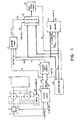
- Fig. 1 is an overall schematic diagram of a paper feed control system for a line printer.
- Fig. 2 is a logic diagram showing details of the direction and pulse generation decode circuitry of Fig. 1.
- Fig. 3 is a logic diagram showing details of an edge detection circuit of Fig. 1.
- Fig. 4 is a timing chart explaining the operation of the pulse generation decode circuitry of Fig. 2.
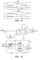
- Fig. 5 is a detailed logic diagram of the detent control portion of Fig. 1.
- Fig. 6 is a schematic showing a printer carriage mechanism for explaining the operation of the detent control of Fig. 5.
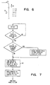
- Fig. 7 is a flow chartfor showing the operation of the carriage control of Fig. 1 under microprocessor control.
- As seen in Fig. 1, a forms feed system comprises carriage motors M1 and M2 connected to a
transport assembly 10 for a line printer or the like.Transport assembly 10 may be -a mechanical assembly including one or more paper feed devices such as paper feed tractors connected to be driven by upper and lower drive shafts rotatably supported on a carriage frame. Motors M1 and M2 which are connected in tandem by suitable gearing or pulleys to the upper and lower drive shafts in any well known manner as indicated by broken lines 11 are preferably high speed low inertia permanent magnet dc servo motors connected to be energized in either forward or reverse directions by motor drive circuits such asH drive circuitry 12. H-drive circuitry 12 is a well known bridge network comprising power transistors which are switched to connect the motors M1 and M2 to a power source to obtain forward and reverse operation. - The motion indicating means comprises an optical encoder consisting of an
emitter disk 13 andoptical transducers Disk 13 is constructed of opaque material having transparent slits 17 arrranged in a single circular track. The slits 17 are uniformly spaced. In a preferred embodiment, the angular spacing is one (1) degree. Thus a complete track has three hundred sixty slits 17.Disk 13 is coupled to motors M1 and M2 as indicated bybroken line 16 and thus moves synchronously therewith.Transducers Transducers circuit 18 which among other things explained hereinafter converts them to purified binary motion signals A, A, B, B and transition signals A EDGE and B EDGE. As seen in Fig. 4, the purified motion signals A and B are square wave binary signals having leading and trailing edges which are ninety electrical or 1/4 mechanical degrees out of phase with each other. The span from the leading edge of signal A or B to the next leading edge thereof represents one degree of rotary motion ofdisk 13. For forward (FWD) motion, the leading edge of signal A precedes the leading edge of signal B. For reverse (REV) motion, the leading edge of signal B precedes the leading edge of signal A. - The motion indicating means also include means for converting the motion signals A Emitter and B Emitter into fine resolution displacement pulses.
Decode circuit 18 receives the binary motion signals A Emitter and B Emitter fromtransducers decode circuit 18 supplies 1/4 degree pulses online 19 to one input ofdisplacement counter 21 and online 22 to switchingcircuit 23.Decode circuit 18 also decodes the motion signals A and B and produces the binary direction signal FWD/ REV which is applied online 20 to a second input ofdisplacement counter 21. - Fig. 3 shows an edge detection circuit for producing the purified motion signals A, A, and an A EDGE detection pulse which comprises series connected latches 24-27 with an output connected to one input of exclusive OR
circuit EOR 28.Decode circuit 18 includes a second edge detection circuit for producing purified motion signals B, B, and B EDGE but is not shown since it is identical in structure and operation to the circuit of Fig. 3. The edge detection circuit of Fig. 3 operates in the following manner.Latch 24 is set by the combination of the leading edge of the A Emitter motion signal fromtransducer 14 and a specific clock pulse of a series of high resolution clock pulses occurring at selected time periods to activate the latches 24-27 in sequence.Latch 25 is set by a second clock pulse and an output fromlatch 24. Whenlatch 25 is set, a valid A Emitter has been detected and a purified motion signal A is produced onoutput line 29.Latches latches EOR 28 on line 31. The width of the A EDGE pulse is determined by the time betweenlatch 26 and latch 27 turning on. When the A Emitter changes state, latches 24-27 are reset sequentially in the same order by a series of reset clock pulses.Latch 24 is reset by the combination of the trailing edge of A Emitter and the first reset clock pulse.Latch 25 is reset by the combination oflatch 24 and the second reset clock pulse. In resetting, latch 25 generates purified motion signal A onoutput line 30.Latches EOR 28 produces a second A EDGE signal on line 31. The width of the second A EDGE signal is determined by the time interval betweenlatch 26 and latch 27 going off. Thus the circuit of Fig. 3 detects the leading and trailing edges of the A Emitter signal. - A specific type of
decode circuit 18, as shown in Fig. 2, comprises forward decode circuits 1f4f and reverse decode circuits 1R-4R. The outputs offorward decode circuits 1 F-4F are fed through ORcircuit 32 to one input of theOR circuit 33 and to the set input S ofdirection latch 34. The outputs of reverse decode circuits 1R-4R are connected through ORcircuit 35 to the second input of OR 33 and the reset input R ofdirection latch 34. The A and B EDGE signals and the motion signals A, A, B, and B generated by the edge detection circuits as in Fig. 3 are decoded bydecode circuits 1 F-4F or 1R-4R to actuate OR 33 which generates 1/4 degree pulses online 19. For example, a 1/4 degree pulse of a short duration is generated byOR 33 online 19 by the combination of A EDGE, B and A being decoded bydecode circuit 1F. Similarly, the combination of A EDGE, B, and A produces a short duration pulse from OR 33 in response to a decode output fromdecode circuit 4R. - FWD/REV signals are generated on
line 20 from the N output of direction latch 34 in response to the sequence in which binary signals A and B fromtransducers cause decode circuit 1F to setdirection latch 34 producing a FWD signal online 20. If thereafter a B EDGE, A, and B follow, direction latch 34 remains set as a result of the signal fromdecode circuit 2F through ORcircuit 32 to the S input. A REV signal is produced online 20 bydirection latch 34 when reset by signal from decode circuit 1R in response to the combination of inputs B EDGE, A, andB. Direction latch 34 remains reset bydecode circuit 2R if A EDGE, B, and A follow. - Basically decode
circuit 18 is a frequency multiplier which as seen in Fig. 4 provides fineresolution displacement pulses 22 for each transition of signal A and B. Thus, it is possible to have the displacement indicia 17 more widely spaced while producing a fine displacement pulse train. In a particular configuration,emitter disk 13 can have three hundred sixty displacement indicia with one degree spacing. With thisarrangement decode circuit 18 produces 1440 1/4 degree displacement pulses for every complete revolution ofdisk 13 thereby providing precise position control within a movement of one or more line spaces or fractions thereof. - The motion indicating means, in accordance with this invention also includes means for producing coarse resolution displacement pulses which are generated during motion of
disk 13 and which represent motion indicative of a larger fraction of a line space. This function is provided by thedisplacement counter 21 designed to count a predetermined number of fine resolution displacement pulses during extended bidirectional motion ofdisk 13 and generating a short duration displacement pulse indicating a larger increment of movement each time the predetermined number count is reached. In the embodiment illustrated, and as seen in Fig. 4, displacement counter 21 counts 1/4 degree displacement pulses received online 19 and supplies 1 degree displacement pulses online 36 to switchingcircuit 23. - As shown in more detail in Fig. 5,
displacement counter 21 is a 4-bit bidirectional counter having anoutput 37 connected to decodecircuits decode circuits circuit 40 to the reset input R ofdisplacement counter 21 byline 41 and byline 36 to the ANDcircuit 42 of switchingcircuit 23.Displacement counter 21 is incremented by 1/ 4 degree pulses online 19 with a FWD direction signal present online 20.Displacement counter 21 is reset to zero by a 1 degree pulse online 41 fromdecode circuit 39 each time a four count is reached.Displacement counter 21 is decremented by 1/4 pulses online 19 when a REV signal is present online 20.Displacement counter 21 is reset to zero by a 1 degree pulse online 41 fromdecode circuit 38 each time a twelve count is reached. - Motors M1 and M2 are operated to feed a continuous print medium in increments of one or more line spaces and then stop for printing. Each feed operation is performed in accordance with a speed profile in which motors M1 and M2 are accelerated rapidly to a desired velocity. The motors are then operated to maintain the velocity essentially constant. After a predetermined displacement relative to the start position and in advance of the final stop position motors M1 and M2 are electrically braked, i.e., reversed, to cause rapid deceleration and stopping. When the stop position is reached, the motors are deenergized. Because motors M1 and M2 are dc servomotors, they are now essentially uncontrolled and mechanical vibration and other perturbations will cause movement so that the print medium becomes vertically misaligned. In this phase of operation the system monitors the position of the motors M1 and M2 relative to the desired stop position and operates them if movement exceeds a certain tolerance.
- The system for controlling the operation of motors M1 and M2 for positioning a print medium basically consists of
position counter 43,microprocessor 44, and drivecontrol 45, interconnected bydata bus 46 andaddress bus 47.Position counter 43 preferably is an 8-bit up/down electronic counter which is incremented or decremented by 1/4 or 1 degree displacement pulses received online 48 fromdecode circuit 18 anddisplacement counter 21 via switchingcircuit 23. A direction signal FWD/REV online 49 fromdecode circuit 18 controls position counter 43 to increment or decrement.Position counter 43 has an output connection to acount decode circuit 50 which is designed and operated to generate interrupt requests (IRQ's) online 51 tomicroprocessor 44 in response to selected count values registered in position counter 43 during drive and detent operation. A specific count decoded bycircuit 50 which results in an IRQ might be binary zero indicative of the position counter 43 having been decremented from a preset number of 1 degree displacement pulses in response to motion of the motors to an intermediate position or to the desired stop position. Other counts decoded bycircuit 50 for detecting movement of motors M1 and M2 during printing (detent) might be FF, FE, 0, 1, and 2 indicating specific numbers of displacement pulses generated bydecode circuit 18. This is illustrated in Fig. 6 wheretype element 52 such as a revolving type band defines the print line or 0 position. Counts FF and FE represent 1/4 and 1/2 degree of forward drift movement whereby the line position ofprint medium 53 is misaligned in the minus direction, i.e., below the print line.Counts 1 and 2 represent 1/4 and 1/2 degree reverse movement whereby the line position ofprint medium 53 is misaligned in the plus direction, i.e., above the print line.Arrow 54 indicates the forward direction which is the normal direction for feedingprint medium 53 to effect line spacing. - As shown in Fig. 5, switching
circuit 23 includes a displacementpulse selection latch 55 having Q and Q outputs connected to ANDcircuits 56 42 respectively. Using positive logic, a down DETENT signal online 57 from microprocessor 44 (see also Fig. 1) to the set input S oflatch 55 gates 1 degree pulses online 36 through ANDcircuit 42 and ORcircuit 58 ontoline 48 to positioncounter 43. An up level DETENT signal online 57 frommicroprocessor 44 is raised byinverter 59 connected to the reset input R oflatch 55. This gates 1/4 degree pulses online 22 fromdecode circuit 18. -
Motor drive control 45 comprises logic circuitry for controlling the direction and current level for operating motors M1 and M2. While the logic circuits ofcontrol 45 might take various forms, it could include amplifiers, predrivers and other circuit devices that provide control signals onbus 60 that selectively turn on the power transistors of the H-drive 12 in response to direction signals FWD/REV online 61 frommicroprocessor 44 to obtain forward and reverse drive and braking of the motors M1 and M2.Motor drive control 45 might also include a DAC circuit which in response to a digital input applied ondata bus 46 with the appropriate address onaddress bus 47 both frommicroprocessor 44 would produce an analog signal onbus 60 to H-drive 12 whereby the current level supplied to motors M1 and M2 from the power source associated with H-drive 12 is controlled to obtain the acceleration constant velocity and deceleration of the motors. -
Microprocessor 44 receives commands and data from an external source indicative of the extent of motion required of motors M1 and M2. The external source (not shown) may be a host system which can be a central data processing system, a communication channel connected to a data source, or another microprocessor all of which supply commands and data to be printed.Microprocessor 44 is an electronic data processor using microcode to decode and execute commands to initiate monitor and control the sequence of operations of motors M1 and M2 as previously described. prior to receipt of a move command from the host system, the microprocessor will be operating the motors M1 and M2 in a detent or stop mode. As previously describedmicroprocessor 44 will have operatedswitch circuit 23 to gate 1/4 degree displacement pulses fromdecode circuit 18 to positioncounter 43. A direction signal fromdecode circuit 18 will determine whether theposition counter 43 is counting up or down as a result of drive shaft movement. Note that position counter 43 decrements in response to a FWD signal and increments in response to REV signal online 49 fromdecode 18. In accordance with this invention,displacement counter 21 is also counting 1/4 degree pulses but in the opposite direction, i.e.,displacement counter 21 increments in response to a FWD signal and decrements in response to a REV signal fromdecode circuit 18 online 20. If movement exceeds the error limit, an IRQ from position decode 50activates microprocessor 44 which responds with direction control and digital value to themotor control 45 which switches the H-drive 12 to apply short drive pulses to the motors M1 and M2. This causes the motors M1 and M2 to move in the direction opposite the error movement. In so moving, theposition counter 43 and thedisplacement counter 21 are incremented or decremented until a zero count is again reached and position decode 50 generates a second IRQ which causesmicroprocessor 44 to terminate motor operation. In the course of the detent mode of operation, a move command may be received bymicroprocessor 44 which then begins the sequence of operations leading to the execution of the move command. As shown in the flow chart of Fig. 7,microprocessor 44 determines whether a correct cycle is in progress. If so, the operation is completed until position counter 43 again registers a zero count whereupon the start- up procedure is initiated. If not, the start up procedure is initiated immediately as shown byblock 62.Microprocessor 44 in accordance with its microcode raises theFWD line 60 tomotor control 45, drops the DETENT signal online 36 to switchcircuit 23 thereby activatingpulse selection latch 55 to gate 1 degree pulses through ANDcircuit 42 to positioncounter 43.Position counter 43 then receives the initial 1 degree pulse count fromdata bus 46. During the sequence of operation listed inblock 62, displacement counter 21 counts and stores 1/4 degree pulses generated bydecode circuit 18 in response to error movement of motors M1 and M2 as indicated by the quadrature motion signals A Emitter and B Emitter fromtransducers microprocessor 44 control. In the embodiment illustrated, displacement counter 21 counts, holds and compensates for error movement over a range of-(i.e., reverse) 3 (1/4) degrees to (i.e., forward) 3 (1/4) degrees. Thusdisplacement counter 21 holds a maximum error of .75 degrees of movement relative to the zero position and compensates over a range of 1.5 degrees total. Upon completion of the setting of theposition counter 43 and the directionsignal FWD microprocessor 44 sends a digital value onbus 46, raises theFWD line 61 and issues a GO command tomotor control 45 which turns on the H-drive 12 to operate the motors to feed theprint medium 53 in the FWD direction. The change of direction is immediately sensed bydecode circuit 18 and a FWD signal generated online 20 todisplacement counter 21. Ifdisplacement counter 21 has decremented to a negative count, it begins incrementing toward a zero count condition and continues counting until a four count is decoded bydecode circuit 39 which generates a 1 degree pulse online 36 to positioncounter 43. Thus ineffect displacement counter 21 has counted more than four 1/4 degree pulses thus compensating for negative misalignment of theprint medium 53 with the print line. If shaft movement had occurred in the forward direction prior to the GO command frommicroprocessor 44 tomotor control 45,displacement 21 counter counts less than four 1/4 degree pulses after the GO signal before a 1 degree pulse is supplied to position counter 43 thus compensating for positive error and misalignment of theprint medium 53. - Thus it will be seen that an improved positioning control system has been provided by the invention in which precise positioning is possible when operating at high incrementing speeds and where positioning errors can occur due to perturbations created by printing and the starting and stopping of the dc motor. It is also apparent that an accurate self compensating positioning system has been provided for precise line spacing . of a print medium relative to a print line which operates independently of a microprocessor and allows the microprocessor to be free to perform numerous other operations required before operating to control the incrementing of a print medium at one or more line spaces.
Claims (4)
Applications Claiming Priority (2)
| Application Number | Priority Date | Filing Date | Title |
|---|---|---|---|
| US06/522,144 US4591969A (en) | 1983-08-11 | 1983-08-11 | Microprocessor-controlled positioning system |
| US522144 | 1990-05-11 |
Publications (2)
| Publication Number | Publication Date |
|---|---|
| EP0134017A1 EP0134017A1 (en) | 1985-03-13 |
| EP0134017B1 true EP0134017B1 (en) | 1987-10-28 |
Family
ID=24079641
Family Applications (1)
| Application Number | Title | Priority Date | Filing Date |
|---|---|---|---|
| EP84109397A Expired EP0134017B1 (en) | 1983-08-11 | 1984-08-08 | Microprocessor - controlled positioning system |
Country Status (6)
| Country | Link |
|---|---|
| US (1) | US4591969A (en) |
| EP (1) | EP0134017B1 (en) |
| JP (1) | JPS6044378A (en) |
| BR (1) | BR8403980A (en) |
| CA (1) | CA1221933A (en) |
| DE (1) | DE3466957D1 (en) |
Families Citing this family (38)
| Publication number | Priority date | Publication date | Assignee | Title |
|---|---|---|---|---|
| US5060151A (en) * | 1984-07-19 | 1991-10-22 | Cymatics, Inc. | Speed control for orbital shaker with reversing mode |
| JPS6151353A (en) * | 1984-08-21 | 1986-03-13 | Brother Ind Ltd | Dot matrix type serial printer |
| JPS6163861A (en) * | 1984-09-04 | 1986-04-02 | Sharp Corp | Copying process timing control system |
| US4811133A (en) * | 1985-05-22 | 1989-03-07 | Fuji Photo Film Co., Ltd. | Electronic still video record/play head positioner having both open and closed loop positioning control |
| EP0234933B1 (en) * | 1986-02-28 | 1992-02-05 | Nec Corporation | Data output control system |
| US4734868A (en) * | 1986-07-21 | 1988-03-29 | Vfn Technology Inc. | Precision paper transport system |
| US4845416A (en) * | 1987-02-13 | 1989-07-04 | Caterpillar Inc. | Electronic valve actuator |
| GB8704051D0 (en) * | 1987-02-20 | 1987-03-25 | Thermoteknix Systems Ltd | Printer control system |
| JP2550570B2 (en) * | 1987-04-16 | 1996-11-06 | ブラザー工業株式会社 | Printer |
| JPH01202462A (en) * | 1988-02-09 | 1989-08-15 | Citizen Watch Co Ltd | Printing controller in serial printer |
| JP2624744B2 (en) * | 1988-02-18 | 1997-06-25 | 株式会社テック | How to set character width of printing machine |
| US5095452A (en) * | 1988-05-30 | 1992-03-10 | Nippondenso Co., Ltd. | Device for accurately displaying physical measure by adjusting the outputs from pulse counters |
| FR2642004B1 (en) * | 1988-12-30 | 1995-02-03 | Oce Graphics France | LARGE WIDTH THERMAL PRINTER |
| US4935878A (en) * | 1989-01-04 | 1990-06-19 | Calcomp Inc. | System friction compensation in vector plotters |
| JPH03139185A (en) * | 1989-10-24 | 1991-06-13 | Mita Ind Co Ltd | Abnormality detector for rotation detector |
| WO1992011589A1 (en) * | 1990-12-17 | 1992-07-09 | Eastman Kodak Company | Programmable divider up/down counter with hysteresis |
| JP2797728B2 (en) * | 1991-02-13 | 1998-09-17 | ブラザー工業株式会社 | Pulse generator waveform processing circuit |
| EP0502534B1 (en) * | 1991-03-06 | 1997-12-17 | Hitachi, Ltd. | Encoder |
| US5405069A (en) * | 1992-02-25 | 1995-04-11 | International Business Machines Corporation | Paper motion detection system |
| US5240334A (en) * | 1992-06-04 | 1993-08-31 | Saul Epstein | Hand held multiline printer with base member for guiding |
| JPH07251995A (en) * | 1994-03-16 | 1995-10-03 | Fujitsu Ltd | Medium conveyance control device |
| EP0680829A3 (en) * | 1994-05-03 | 1995-12-27 | Hewlett Packard Co | Optical control system for media handling assemblies in printers. |
| US5731680A (en) * | 1995-06-29 | 1998-03-24 | Eastman Kodak Company | Method and apparatus for registering a sheet with an image-bearing member |
| US5823693A (en) * | 1995-11-30 | 1998-10-20 | Intermec Ip Corp. | Gapless label media and printing apparatus for handling same |
| US5915865A (en) * | 1996-12-05 | 1999-06-29 | Intermec Ip Corp. | Method and apparatus for compensating for printer top-of-form and image stretch errors |
| US6428224B1 (en) | 1999-12-21 | 2002-08-06 | Lexmark International, Inc. | Error mapping technique for a printer |
| US6641134B1 (en) * | 2000-10-27 | 2003-11-04 | Heidelberger Druckmaschinen Ag | System and method for improved registration performance |
| JP4497703B2 (en) * | 2000-10-31 | 2010-07-07 | キヤノン株式会社 | Recording apparatus and recording medium transport mechanism control method |
| JP2002137469A (en) * | 2000-10-31 | 2002-05-14 | Canon Inc | Method for controlling sheet member carrier and recorder |
| US7126107B2 (en) | 2003-03-14 | 2006-10-24 | Lexmark International, Inc. | Methods and apparatuses for sensing rotational position of a component in a printing device |
| US6830399B2 (en) * | 2003-03-14 | 2004-12-14 | Lexmark International, Inc. | Methods and systems for compensation of media indexing errors in a printing device |
| US7021735B2 (en) | 2003-03-28 | 2006-04-04 | Lexmark International, Inc. | Reduction of color plane alignment error in a drum printer |
| JP4447891B2 (en) * | 2003-10-31 | 2010-04-07 | キヤノン株式会社 | DC motor control apparatus and recording apparatus |
| JP4833617B2 (en) * | 2005-03-14 | 2011-12-07 | 株式会社リコー | Print medium transport apparatus and print medium transport method |
| US7536533B2 (en) * | 2005-09-30 | 2009-05-19 | Silicon Laboratories Inc. | MCU based motor controller with pre-load register and DMA controller |
| US7898207B2 (en) * | 2007-12-04 | 2011-03-01 | Pitney Bowes Inc. | Method for controlling a DC motor |
| JP6198470B2 (en) * | 2012-07-05 | 2017-09-20 | キヤノン株式会社 | Conveying apparatus and recording apparatus |
| FR3032475B1 (en) * | 2015-02-09 | 2017-03-03 | Inteva Products Llc | APPARATUS AND METHOD FOR DETECTING AND PREVENTING MOVEMENT OF AN ENGINE IN A DEVICE OF A SYSTEM |
Family Cites Families (12)
| Publication number | Priority date | Publication date | Assignee | Title |
|---|---|---|---|---|
| BE795860A (en) * | 1972-02-25 | 1973-08-23 | Xerox Corp | HIGH SPEED PRINTING MACHINES WITH TRAVEL COMPENSATION TROLLEY CABLE |
| DE2258546C2 (en) * | 1972-11-29 | 1982-10-21 | Siemens AG, 1000 Berlin und 8000 München | Device for paper feed monitoring in printers |
| US3914677A (en) * | 1973-06-08 | 1975-10-21 | Sperry Rand Corp | Precision motion control device or the like |
| JPS5460671A (en) * | 1977-10-21 | 1979-05-16 | Ricoh Co Ltd | Positioning system |
| JPS55147785A (en) * | 1979-05-08 | 1980-11-17 | Nippon Keieiki Kk | Platen feed control method for japanese sentence typewriter |
| JPS55154682A (en) * | 1979-05-22 | 1980-12-02 | Hitachi Koki Co Ltd | Paper feed controller |
| US4312033A (en) * | 1979-07-31 | 1982-01-19 | Sweeney James S | Digital motor control for positioning system |
| US4261039A (en) * | 1979-10-19 | 1981-04-07 | International Business Machines Corporation | Microprocessor controlled positioning system |
| US4304497A (en) * | 1979-10-19 | 1981-12-08 | International Business Machines Corporation | Detection of multiple emitter changes in a printer subsystem |
| US4277191A (en) * | 1980-01-28 | 1981-07-07 | International Business Machines Corporation | Printer system having microprocessor control |
| US4349770A (en) * | 1980-07-22 | 1982-09-14 | Xerox Corporation | Electronic damping apparatus |
| JPS6013573A (en) * | 1983-07-05 | 1985-01-24 | Fuji Xerox Co Ltd | Multicolor transfer-type thermal recorder |
-
1983
- 1983-08-11 US US06/522,144 patent/US4591969A/en not_active Expired - Fee Related
-
1984
- 1984-04-19 JP JP59077663A patent/JPS6044378A/en active Granted
- 1984-07-06 CA CA000458369A patent/CA1221933A/en not_active Expired
- 1984-08-08 DE DE8484109397T patent/DE3466957D1/en not_active Expired
- 1984-08-08 EP EP84109397A patent/EP0134017B1/en not_active Expired
- 1984-08-09 BR BR8403980A patent/BR8403980A/en not_active IP Right Cessation
Also Published As
| Publication number | Publication date |
|---|---|
| DE3466957D1 (en) | 1987-12-03 |
| JPH0526667B2 (en) | 1993-04-16 |
| CA1221933A (en) | 1987-05-19 |
| EP0134017A1 (en) | 1985-03-13 |
| US4591969A (en) | 1986-05-27 |
| JPS6044378A (en) | 1985-03-09 |
| BR8403980A (en) | 1985-07-09 |
Similar Documents
| Publication | Publication Date | Title |
|---|---|---|
| EP0134017B1 (en) | Microprocessor - controlled positioning system | |
| US4869610A (en) | Carriage control system for printer | |
| US4755070A (en) | Circuit for actuating electric motors, especially in an electronic typewriter | |
| US4486693A (en) | Motor velocity control | |
| EP0022457B1 (en) | Method of, and circuit for, controlling the detenting of multiphase stepper motors | |
| US4761598A (en) | Torque-angle stabilized servo motor drive | |
| US3950685A (en) | Dc motor position controller | |
| EP0077446B1 (en) | Print head velocity control system using analog and digital feedback | |
| US3914677A (en) | Precision motion control device or the like | |
| EP0077455A1 (en) | Print head control system with controlled acceleration and deceleration | |
| JPS585600B2 (en) | Step motor speed control method and device | |
| US3924721A (en) | Digital logic and servo system for print head rotate control | |
| US4802777A (en) | Print wheel and carriage drive system for a printer | |
| EP0051417B1 (en) | Method and apparatus for use in adjusting an installation position of a switch member in a numerical control system | |
| KR860002200B1 (en) | Velocity-position servo with improved gain control | |
| US4529325A (en) | Technique for compensation for bandwidth limitations of microprocessor utilized for serial printer control | |
| US4348622A (en) | DC Motor drive control system | |
| US4251161A (en) | Control unit for a serial printer | |
| JPS58144593A (en) | Driving device for motor | |
| US4307967A (en) | Serial printing apparatus | |
| US5147143A (en) | Printer carriage homing mechanism | |
| JPS6316318Y2 (en) | ||
| EP0143763A1 (en) | Method of controlling a printer | |
| JPS60236781A (en) | Serial printer controlling system | |
| JPS6015183A (en) | Printing control system |
Legal Events
| Date | Code | Title | Description |
|---|---|---|---|
| PUAI | Public reference made under article 153(3) epc to a published international application that has entered the european phase |
Free format text: ORIGINAL CODE: 0009012 |
|
| 17P | Request for examination filed |
Effective date: 19841123 |
|
| AK | Designated contracting states |
Designated state(s): CH DE FR GB IT LI |
|
| 17Q | First examination report despatched |
Effective date: 19860205 |
|
| R17C | First examination report despatched (corrected) |
Effective date: 19860729 |
|
| GRAA | (expected) grant |
Free format text: ORIGINAL CODE: 0009210 |
|
| AK | Designated contracting states |
Kind code of ref document: B1 Designated state(s): CH DE FR GB IT LI |
|
| REF | Corresponds to: |
Ref document number: 3466957 Country of ref document: DE Date of ref document: 19871203 |
|
| ET | Fr: translation filed | ||
| ITF | It: translation for a ep patent filed |
Owner name: IBM - DR. ARRABITO MICHELANGELO |
|
| PLBE | No opposition filed within time limit |
Free format text: ORIGINAL CODE: 0009261 |
|
| STAA | Information on the status of an ep patent application or granted ep patent |
Free format text: STATUS: NO OPPOSITION FILED WITHIN TIME LIMIT |
|
| PG25 | Lapsed in a contracting state [announced via postgrant information from national office to epo] |
Ref country code: LI Effective date: 19880831 Ref country code: CH Effective date: 19880831 |
|
| 26N | No opposition filed | ||
| REG | Reference to a national code |
Ref country code: CH Ref legal event code: PL |
|
| ITTA | It: last paid annual fee | ||
| PGFP | Annual fee paid to national office [announced via postgrant information from national office to epo] |
Ref country code: GB Payment date: 19920722 Year of fee payment: 9 |
|
| PGFP | Annual fee paid to national office [announced via postgrant information from national office to epo] |
Ref country code: FR Payment date: 19920724 Year of fee payment: 9 |
|
| PGFP | Annual fee paid to national office [announced via postgrant information from national office to epo] |
Ref country code: DE Payment date: 19920822 Year of fee payment: 9 |
|
| PG25 | Lapsed in a contracting state [announced via postgrant information from national office to epo] |
Ref country code: GB Effective date: 19930808 |
|
| GBPC | Gb: european patent ceased through non-payment of renewal fee |
Effective date: 19930808 |
|
| PG25 | Lapsed in a contracting state [announced via postgrant information from national office to epo] |
Ref country code: FR Effective date: 19940429 |
|
| PG25 | Lapsed in a contracting state [announced via postgrant information from national office to epo] |
Ref country code: DE Effective date: 19940503 |
|
| REG | Reference to a national code |
Ref country code: FR Ref legal event code: ST |