JP4447891B2 - DC motor control apparatus and recording apparatus - Google Patents
DC motor control apparatus and recording apparatus Download PDFInfo
- Publication number
- JP4447891B2 JP4447891B2 JP2003372459A JP2003372459A JP4447891B2 JP 4447891 B2 JP4447891 B2 JP 4447891B2 JP 2003372459 A JP2003372459 A JP 2003372459A JP 2003372459 A JP2003372459 A JP 2003372459A JP 4447891 B2 JP4447891 B2 JP 4447891B2
- Authority
- JP
- Japan
- Prior art keywords
- motor
- torque
- information
- stop
- speed
- Prior art date
- Legal status (The legal status is an assumption and is not a legal conclusion. Google has not performed a legal analysis and makes no representation as to the accuracy of the status listed.)
- Expired - Fee Related
Links
Images


Classifications
-
- G—PHYSICS
- G05—CONTROLLING; REGULATING
- G05B—CONTROL OR REGULATING SYSTEMS IN GENERAL; FUNCTIONAL ELEMENTS OF SUCH SYSTEMS; MONITORING OR TESTING ARRANGEMENTS FOR SUCH SYSTEMS OR ELEMENTS
- G05B19/00—Programme-control systems
- G05B19/02—Programme-control systems electric
- G05B19/18—Numerical control [NC], i.e. automatically operating machines, in particular machine tools, e.g. in a manufacturing environment, so as to execute positioning, movement or co-ordinated operations by means of programme data in numerical form
- G05B19/404—Numerical control [NC], i.e. automatically operating machines, in particular machine tools, e.g. in a manufacturing environment, so as to execute positioning, movement or co-ordinated operations by means of programme data in numerical form characterised by control arrangements for compensation, e.g. for backlash, overshoot, tool offset, tool wear, temperature, machine construction errors, load, inertia
-
- B—PERFORMING OPERATIONS; TRANSPORTING
- B41—PRINTING; LINING MACHINES; TYPEWRITERS; STAMPS
- B41J—TYPEWRITERS; SELECTIVE PRINTING MECHANISMS, i.e. MECHANISMS PRINTING OTHERWISE THAN FROM A FORME; CORRECTION OF TYPOGRAPHICAL ERRORS
- B41J19/00—Character- or line-spacing mechanisms
- B41J19/18—Character-spacing or back-spacing mechanisms; Carriage return or release devices therefor
- B41J19/20—Positive-feed character-spacing mechanisms
- B41J19/202—Drive control means for carriage movement
- B41J19/205—Position or speed detectors therefor
- B41J19/207—Encoding along a bar
-
- G—PHYSICS
- G05—CONTROLLING; REGULATING
- G05B—CONTROL OR REGULATING SYSTEMS IN GENERAL; FUNCTIONAL ELEMENTS OF SUCH SYSTEMS; MONITORING OR TESTING ARRANGEMENTS FOR SUCH SYSTEMS OR ELEMENTS
- G05B2219/00—Program-control systems
- G05B2219/30—Nc systems
- G05B2219/41—Servomotor, servo controller till figures
- G05B2219/41057—Stiffness, deformation of slide, drive
-
- G—PHYSICS
- G05—CONTROLLING; REGULATING
- G05B—CONTROL OR REGULATING SYSTEMS IN GENERAL; FUNCTIONAL ELEMENTS OF SUCH SYSTEMS; MONITORING OR TESTING ARRANGEMENTS FOR SUCH SYSTEMS OR ELEMENTS
- G05B2219/00—Program-control systems
- G05B2219/30—Nc systems
- G05B2219/45—Nc applications
- G05B2219/45187—Printer
Landscapes
- Engineering & Computer Science (AREA)
- Human Computer Interaction (AREA)
- Manufacturing & Machinery (AREA)
- Physics & Mathematics (AREA)
- General Physics & Mathematics (AREA)
- Automation & Control Theory (AREA)
- Character Spaces And Line Spaces In Printers (AREA)
- Control Of Direct Current Motors (AREA)
- Stopping Of Electric Motors (AREA)
- Handling Of Sheets (AREA)
Description
本発明は、DCモータ制御装置とおよび記録装置に関するものである。 The present invention relates to a DC motor control device and a recording device.
近年、プリンタにおいて、画像品位の向上と共に、稼動音の低下が望まれている。特に、記録時の騒音発生源の少ないインクジェット記録装置においては、記録ヘッドを走査するための駆動手段として、DCモータとリニアエンコーダを使用し、低騒音化を実現している。 In recent years, printers have been desired to improve the image quality and reduce the operating sound. In particular, in an ink jet recording apparatus with few noise generation sources during recording, a DC motor and a linear encoder are used as drive means for scanning the recording head, thereby realizing low noise.
今日では、これに加え、用紙搬送用の駆動手段としてもDCモータとロータリエンコーダが採用されつつある。低騒音化に関してはDCモータを採用するだけで効果が期待できるが、高精度な搬送を行うためには高度な停止制御技術と機械精度が必要となる。 Nowadays, in addition to this, a DC motor and a rotary encoder are being adopted as drive means for paper conveyance. For reducing noise, an effect can be expected simply by adopting a DC motor, but advanced stop control technology and machine accuracy are required to perform highly accurate conveyance.
DCモータの停止方法(停止制御)は、基本的には目標停止位置にローラの回転がたどり着いた時にDCモータのトルクをゼロにして惰性で停止させる手法が一般的である。 As a DC motor stop method (stop control), basically, when the rotation of the roller reaches the target stop position, the DC motor torque is set to zero and the motor is stopped by inertia.
また、上記の手法以外にも、目標停止位置より所定距離手前の位置での速度情報から目標停止位置に到達する手前の所定位置に到達すると予想される所定時間経過後にモータへの通電遮断を行うことにより停止する方法が提案されている。
しかしながら、目標停止位置でDCモータのトルクをゼロにした場合、DCモータのトルクを伝達する為のベルトやギアなどのトルク伝達手段(トルク伝達部材)が変形することにより停止の際の外乱(力)が発生する。以後、この力(外乱)のことを「弾性変形チャージ力」と呼び説明する。この弾性変形チャージ力は被駆動体の駆動方向と逆方向のトルクとして発生する。この弾性変形チャージ力により、目標停止位置でDCモータのトルクをゼロにすると被駆動体が移動し、停止位置での位置ずれが起こる。 However, when the torque of the DC motor is reduced to zero at the target stop position, a disturbance (force) at the time of stopping due to deformation of the torque transmission means (torque transmission member) such as a belt or gear for transmitting the torque of the DC motor. ) Occurs. Hereinafter, this force (disturbance) will be referred to as “elastic deformation charging force” and will be described. This elastic deformation charging force is generated as torque in the direction opposite to the driving direction of the driven body. With this elastic deformation charging force, when the torque of the DC motor is reduced to zero at the target stop position, the driven body moves and a displacement occurs at the stop position.
図11はその説明図である。Enはエンコーダーの信号に基づく位置信号である。例えば、矢印MV1は、搬送手段によって搬送される被記録媒体の先端位置が、Enのタイミングで停止処理がなされ、位置Pnで停止する(ここで、説明を簡単にするために、停止処理がなされて停止するまで、移動する距離は0とする)。しかし、この弾性変形チャージ力により、距離dだけ移動して位置Pn−1で停止する(矢印MV2)。 FIG. 11 is an explanatory diagram thereof. En is a position signal based on the encoder signal. For example, the arrow MV1 indicates that the leading end position of the recording medium transported by the transport unit is stopped at the timing En and stops at the position Pn (here, for the sake of simplicity, the stop processing is performed). The distance traveled is 0 until the vehicle stops.) However, this elastic deformation charge force moves by a distance d and stops at a position Pn-1 (arrow MV2).
このため、低速度でサーボ駆動時に目標停止位置または目標停止位置の手前でモータへの通電遮断を実行すると、弾性変形チャージ力などにより停止位置がずれ、停止精度が悪くなっていた。 For this reason, when the energization of the motor is cut off before the target stop position or the target stop position at the time of servo driving at low speed, the stop position is shifted due to elastic deformation charging force and the stop accuracy is deteriorated.
上述の課題を解決し、目的を達成するために、本発明のDCモータ制御装置は、DCモータと、前記DCモータからトルクを伝達するトルク伝達部材を含み、前記DCモータから駆動トルクを受けて被駆動体を所定方向に移動させ、前記DCモータのトルクをゼロにする際に前記トルク伝達部材の変形に基づくトルクにより前記被駆動体を前記所定方向と逆向きに移動させる移動手段と、前記被駆動体の移動に伴って、周期的にパルス信号を出力するエンコーダー手段と、前記パルス信号の時間間隔に基づき前記被駆動体の速度情報と位置情報を取得する情報取得手段と、目標停止位置を含む位置プロファイルと前記情報取得手段により取得された前記速度情報と前記位置情報とに基づき、前記DCモータを制御する制御手段と、前記移動手段による前記逆向きの移動による前記被駆動体の停止位置のずれ量を算出する算出手段と、前記目標停止位置を通過してから前記DCモータのトルクをゼロにする停止処理を行うべきタイミングを前記ずれ量に基づいて決定する決定手段とを備え、前記制御手段は、前記決定手段により決定されたタイミングに基づき、前記停止処理を行うことを特徴とする。 In order to solve the above-described problems and achieve the object, a DC motor control device of the present invention includes a DC motor and a torque transmission member that transmits torque from the DC motor, and receives driving torque from the DC motor. Moving means for moving the driven body in a predetermined direction and moving the driven body in a direction opposite to the predetermined direction by a torque based on deformation of the torque transmitting member when the torque of the DC motor is made zero ; Encoder means for periodically outputting a pulse signal as the driven body moves, information acquisition means for acquiring speed information and position information of the driven body based on a time interval of the pulse signal, a target stop position based on the obtained the speed information and the location information by the position profile and the information acquisition means and a control means for controlling the DC motor, the moving hand Calculating means for calculating a shift amount of the stop position of the driven body due to the movement of the reverse by the timing for the stopping process to zero the torque of said DC motor after passing through the target stop position the Determining means for determining based on the amount of deviation , wherein the control means performs the stop processing based on the timing determined by the determining means .
本発明の記録装置は、記録ヘッドを用いて、被記録媒体に記録を行う記録装置であって、DCモータと、前記DCモータからトルクを伝達するトルク伝達部材を含み、前記DCモータから駆動トルクを受けて被記録媒体を所定方向に移動させ、DCモータのトルクをゼロにする際に前記トルク伝達部材の変形に基づくトルクにより前記被記録媒体を前記所定方向と逆向きに移動させる搬送手段と、
前記搬送手段の動作に伴って、周期的にパルス信号を出力するエンコーダー手段と、前記パルス信号の時間間隔に基づき前記搬送手段の速度情報と位置情報を取得する情報取得手段と、停止目標位置を含む位置プロファイルと前記情報取得手段により取得された前記速度情報と前記位置情報とに基づき、前記DCモータを制御する制御手段と、前記搬送手段による前記逆向きの移動による前記被記録媒体の停止位置のずれ量を算出する算出手段と、前記停止目標位置を通過してから前記DCモータのトルクをゼロにする停止処理を行うべきタイミングを前記ずれ量に基づいて決定する決定手段とを備え、前記制御手段は、前記決定手段により決定されたタイミングに基づき、前記停止処理を行うことを特徴とする。
The recording apparatus of the present invention is a recording apparatus that performs recording on a recording medium using a recording head, and includes a DC motor and a torque transmission member that transmits torque from the DC motor, and driving torque from the DC motor. receiving by moving the recording medium in a predetermined direction, and transport means for moving the recording medium in the predetermined direction opposite to the direction by the torque due to the deformation of the torque transmitting member when the torque of the DC motor to zero ,
Along with the operation of the conveying means, an encoder means for periodically outputting a pulse signal, an information obtaining means for obtaining speed information and position information of the conveying means based on a time interval of the pulse signal, and a stop target position based on the position profile and the said velocity information acquired by the information acquisition means and said location information including a control means for controlling the DC motor, the stop position of the recording medium due to the movement of the reverse by the transport means Calculating means for calculating a deviation amount of the motor, and a determining means for determining a timing for performing a stop process for making the torque of the DC motor zero after passing through the stop target position based on the deviation amount, The control means performs the stop process based on the timing determined by the determination means .
以上説明したように、本発明によれば、弾性変形チャージ力などのような、停止時に発生する力を考慮して停止処理を行うことができ、停止精度を向上させることができる。 As described above, according to the present invention, the stop process can be performed in consideration of the force generated during the stop, such as the elastic deformation charge force, and the stop accuracy can be improved.
(実施形態の共通部分の説明)
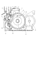
図1は、以下に説明する実施の形態において、共通に用いられる記録装置の斜視図である。図2は用紙搬送駆動系の側面図である。
(Description of common part of embodiment)
FIG. 1 is a perspective view of a recording apparatus commonly used in the embodiments described below. FIG. 2 is a side view of the paper conveyance drive system.
記録装置は、(A)自動給紙部、(B)送紙部、(C)排紙部、(D)キャリッジ部、(E)クリーニング部からなっている。そこで、これらを項目に分けて概略を順次述べる。 The recording apparatus includes (A) an automatic paper feeding unit, (B) a paper feeding unit, (C) a paper discharging unit, (D) a carriage unit, and (E) a cleaning unit. Therefore, these are divided into items and the outline is described sequentially.
(A)自動給紙部
自動給紙部は記録紙Pを積載する圧板1と記録紙Pを給紙する給送ローラ(不図示)がベース2に取り付けられた構成を有する。前記の圧板1には、可動サイドガイド3が移動可能に設けられて、記録紙Pの積載位置を規制している。圧板1はベース2に結合された軸を中心に回転可能で、圧板バネ(不図示)により給送ローラに付勢される。
(A) Automatic Paper Feed Unit The automatic paper feed unit has a configuration in which a
記録紙Pは給紙モータ28の駆動力により、給紙ローラと分離ローラ(不図示)から構成されるニップ部に搬送される。送られた記録紙Pはこのニップ部で分離され、最上位の記録紙Pのみが搬送される。
The recording paper P is conveyed by a driving force of the
(B)送紙部
送紙部は記録紙Pを搬送する搬送ローラ4と用紙位置センサ(不図示)を有している。搬送ローラ4には従動するピンチローラ5が当接して設けられている。ピンチローラ5はピンチローラガイド6に保持され、ピンチローラバネ(不図示)で付勢されることで搬送ローラ4に圧接され、それによって記録紙Pの搬送力を生み出している。さらに、搬送ローラ4の記録紙搬送方向における下流側には、画像情報に基づいて画像を形成するヘッドカートリッジ7が設けられている。
(B) Paper Feed Unit The paper feed unit has a
LFエンコーダセンサ28がLFエンコーダセンサホルダ29に固定され、これがシャーシ12に取り付けられている。また、LFモータ25の駆動力はLFタイミングベルト30を介して搬送ローラ4に圧入固定された搬送ローラギア27に伝達される。このLFエンコーダセンサ28により搬送ローラ4に挿入され搬送ローラギア27に固定されたLFエンコーダスケール26のライン数を読み取ることで得られる搬送ローラ4の回転量(速度)情報からフィードバック制御を行い、DCモータであるLFモーター25を回転制御して記録紙Pが搬送される。送紙部に送られた記録紙Pは、ピンチローラガイド6およびペーパーガイド(不図示)に案内されて、搬送ローラ4とピンチローラ5とのローラ対に送られる。この時、用紙位置センサが搬送されてきた記録紙Pの先端を検知して、これにより記録紙Pの印字位置を求めている。また、印字時には、記録紙Pはローラ対4、5が回転することで、プラテン8上を搬送される。
The
(C)キャリッジ部
キャリッジ部は、ヘッドカートリッジ7を取り付けるキャリッジ9を有している。そしてキャリッジ9は、記録紙Pの搬送方向に対して直角方向に往復走査させるためのガイド軸10およびキャリッジ9の上部後端を保持して記録ヘッド7と記録紙Pとの隙間を維持するガイドレール11によって支持されている。なお、これらガイド軸10およびガイドレール11は、シャーシ12に取り付けられている。
(C) Carriage part The carriage part has a carriage 9 to which the head cartridge 7 is attached. The carriage 9 holds the
キャリッジ9はシャーシ12に取り付けられたDCモータであるキャリッジモータ13によってタイミングベルト14を介して駆動される。このタイミングベルト14は、アイドルプーリ15によって張設、支持されている。さらに、キャリッジ9には、電気基板16からヘッドカートリッジ7へヘッド信号を伝えるためのフレキシブルケーブル17が備えられている。また、キャリッジ9にはキャリッジの位置を検出するリニアエンコーダ(不図示)が搭載されており、シャーシ12に取り付けられたリニアスケール18のライン数を読み取ることにより、キャリッジ9の位置を検出することができる。このリニアエンコーダの信号は、フレキシブルケーブル17を介して、電気基板16に伝えられ処理される。
The carriage 9 is driven via a
上記構成において、記録紙Pに画像形成する時は、画像形成する行位置(記録紙Pの搬送方向の位置)にローラ対4、5が記録紙Pを搬送するとともに、キャリッジモータ13と、リニアエンコーダを使用したフィードバック制御により、キャリッジ9を画像形成する列位置(記録紙Pの搬送方向と垂直な位置)に移動させて、ヘッドカートリッジ7を画像形成位置に対向させる。その後、電気基板16からの信号により、ヘッドカートリッジ7が記録紙Pに向けてインクを吐出して画像が形成される。
In the above configuration, when an image is formed on the recording paper P, the
(D)排紙部
排紙部は、排紙ローラ19に従動して回転可能なように拍車(不図示)が排紙ローラ19に当接されている。排紙ローラ19には、搬送ローラギア27からの駆動が排紙伝達ギア31、排紙ローラギア20を介して伝達される。以上の構成によって、駆動されキャリッジ部で画像形成された記録紙Pは、排紙ローラ19と拍車とのニップに挟まれて搬送され、不図示の排紙トレー等に排出される。
(D) Paper Discharge Unit A spur (not shown) is in contact with the
(E)クリーニング部
クリーニング部は、ヘッドカートリッジ7のクリーニングを行なうポンプ24とヘッドカートリッジ7の乾燥を抑えるためのキャップ21、ヘッドカートリッジ7のフェイス面を清掃するワイパー22、および駆動源であるPGモータ23から構成されている。
(E) Cleaning unit The cleaning unit includes a pump 24 for cleaning the head cartridge 7, a cap 21 for suppressing the drying of the head cartridge 7, a
図3は、図2に示したプリンタの制御構成を説明するブロック図である。図において、401はプリンタ装置のプリンタ制御用のCPUで、ROM402に記憶されたプリンタ制御プログラムやプリンタエミュレーション、印字フォントを利用して印刷処理を制御する。
FIG. 3 is a block diagram illustrating a control configuration of the printer shown in FIG. In the figure,
403はRAMで、印字のための展開データ、ホストからの受信データを蓄える。404はプリンタヘッド、405はモータを駆動するモータドライバ、406はプリンタコントローラで、RAM403のアクセス制御やホスト装置とのデータのやりとりやモータドライバへの制御信号送出を行う。モータドライバ405で駆動する駆動源がDCモータの場合、図示されていないディジタルエンコーダーからの信号を基にプリンタコントローラ406は駆動源の速度情報および位置情報を取得し、この情報に基づいてモータドライバ405を制御して駆動源をサーボコントロールする。407はサーミスタ等で構成される温度センサで、プリンタ装置の温度を検知する。
CPU401はROM402内の制御プログラムにより本体のメカ的/電気的制御を行いつつ、ホスト装置からプリンタ装置へ送られてくるエミュレーションコマンド等の情報をプリンタコントローラ406内のI/Oデータレジスタから読み出し、コマンドに対応した制御をプリンタコントローラ406内のI/Oレジスタ、I/Oポートに書き込み、読み出しを行う。
The
図4は、図3に示したプリンタコントローラ406の詳細構成を説明するブロック図であり、図3と同一のものには同一の符号を付してある。
FIG. 4 is a block diagram for explaining the detailed configuration of the
図において、501はI/Oレジスタで、ホストとのコマンドレベルでのデータのやり取りを行う。502は受信バッファコントローラで、レジスタから受信データをRAM403に直接書き込む。
In the figure,
503は印刷バッファコントローラで、印字時にはRAMの記録データバッファから記録データを読み出し、プリンタヘッド404に対してデータの送出を行う。504はメモリコントローラで、RAM403に対して3方向のメモリアクセスを制御する。505はプリントシーケンスコントローラで、プリントシーケンスをコントロールする。231はホストインターフェースで、ホストとの通信を司る。
図5は、DCモータの制御に使用されるディジタルエンコーダーの動作原理を示す図である。図示されたディジタルエンコーダーは光学式エンコーダであり、LED701が発生した光のうちコードホイール702を通過した光をディテクタ703で検出して信号を発生するように構成されている。
FIG. 5 is a diagram showing the operating principle of a digital encoder used for controlling a DC motor. The illustrated digital encoder is an optical encoder, and is configured to generate a signal by detecting, with a detector 703, light that has passed through a
コードホイール702には、光を透過する部分704と光を透過しない部分705とが決められた間隔で交互に配置されている。ディテクタ703には複数のフォトダイオード706,707,708,709が決められた間隔で配置さており、各フォトダイオード706,707,708,709で検出された光を基に電気信号A 710、電気信号*A 711、電気信号B 712、電気信号*B 713に変換して出力し、出力された電気信号710,711,712,713は、コンパレーター714,715に入力されて差動出力の矩形波形チャネルA716及びチャネルB717として出力される。
In the
一般的にチャネルA716とチャネルB717の信号は位相差90度で、矩形波のパルス数はコードホイール702のスリット数、矩形波の周波数はスリットの移動速度と相関関係がある。つまり、矩形波のパルス数をカウントすることにより駆動体の位置情報、矩形波の周期を測定することにより駆動体の速度情報を得ることができる。
In general, the signals of
ディジタルエンコーダーから出力される信号には、様々な原因によりノイズが発生する可能性がある。このノイズの影響を無くす為に、一般的にディジタルエンコーダーから出力された信号を、デジタルLPF(ローパスフィルタ)を通して使用する。 The signal output from the digital encoder may generate noise due to various causes. In order to eliminate the influence of noise, a signal output from a digital encoder is generally used through a digital LPF (low pass filter).
ここで、位置情報および速度情報の取得タイミングとしては、チャネルA716またはチャネルB717の片側信号の同一エッジ間、チャネルA716またはチャネルB717の片側信号の異なるエッジ間、チャネルA716とチャネルB717の全てのエッジ間など様々な方法が考えられる。つまり、位置情報と速度情報の取得タイミングは必ずしも一致するとは限らない。 Here, the acquisition timing of position information and velocity information includes the same edge of one side signal of channel A716 or channel B717, between different edges of one side signal of channel A716 or channel B717, and between all edges of channel A716 and channel B717. Various methods are conceivable. That is, the acquisition timing of the position information and the speed information does not always match.
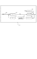
図6は一般的なDCモータの位置制御系を説明する模式図であり、位置サーボをかける場合の手法について示している。DCモータは、PIDコントロールあるいは古典制御と呼ばれる手法で制御されており、以下その手順を説明する。 FIG. 6 is a schematic diagram for explaining a position control system of a general DC motor, and shows a method for applying position servo. The DC motor is controlled by a technique called PID control or classical control, and the procedure will be described below.
まず、制御対象に与えたい目標位置は、6001の理想位置プロファイルという形で与える。本実施例の装置においては、これは該当する時刻においてラインフィードモータによって搬送された紙が到達しているべき絶対位置に該当する。時刻の進行とともに、この位置情報は変化していく。この理想位置プロファイルに対して追値制御を行うことで、本実施例装置の駆動は遂行される。 First, the target position to be given to the control object is given in the form of an ideal position profile 6001. In the apparatus of this embodiment, this corresponds to the absolute position where the paper conveyed by the line feed motor should reach at the corresponding time. This position information changes as time progresses. By performing additional value control on this ideal position profile, the driving of the apparatus of this embodiment is performed.
装置には6005のエンコーダセンサが具備されており、モータの物理的な回転を検知する。6009のエンコーダ位置情報変換手段は、エンコーダセンサが検知したスリット数を加算して絶対位置情報を得る手段であり、6006のエンコーダ速度情報変換手段はエンコーダセンサの信号と、プリンタに内蔵された時計から、現在のラインフィードモータの駆動速度を算出する手段である。 The device is equipped with 6005 encoder sensors to detect the physical rotation of the motor. The encoder position information conversion means 6009 is means for obtaining absolute position information by adding the number of slits detected by the encoder sensor. The encoder speed information conversion means 6006 is obtained from the signal of the encoder sensor and a clock built in the printer. This is means for calculating the current driving speed of the line feed motor.
6001の理想位置プロファイルから、6009の位置情報変換手段により得られた実際の物理的位置を減算した数値を、目標位置に対して足りない位置誤差として、6002以降の位置サーボのフィードバック処理に受け渡す。6002は位置サーボのメジャーループであり、一般的には比例項Pに関する計算を行う手段が知られている。
A numerical value obtained by subtracting the actual physical position obtained by the position information conversion means 6009 from the ideal position profile 6001 is transferred to the position
6002における演算の結果としては、速度指令値が出力される。この速度指令値が、6003以降の速度サーボのフィードバック処理に受け渡される。速度サーボのマイナーループは、比例項P、積分項I、微分項Dに対する演算を行うPID演算により行う手段が一般的である。 As a result of the calculation in 6002, a speed command value is output. This speed command value is passed to 6003 and subsequent speed servo feedback processes. The minor loop of the speed servo is generally a means that performs a PID calculation for calculating the proportional term P, the integral term I, and the differential term D.
本実施例の装置においては、速度指令値の非線形な変化が発生した場合の追従性を改善し、なおかつ追値制御時の微分演算の弊害を防ぐために、一般に微分先行形と呼ばれる手法を示しており、6006で得られたエンコーダ速度情報は、6002で得られた速度指令値との差を取る前に、6007の微分演算を通される。この手法自体は本発案の主題となるものではなく、制御対象の系の特性によっては、6003において該微分演算を行えば充分なものもある。 In the apparatus of the present embodiment, in order to improve the followability when a non-linear change in the speed command value occurs, and to prevent the adverse effect of the differential operation during the follow-up control, a method generally called a differential leading form is shown. The encoder speed information obtained in 6006 is subjected to a differential operation in 6007 before taking the difference from the speed command value obtained in 6002. This method itself is not the subject of the present invention, and depending on the characteristics of the system to be controlled, it may be sufficient to perform the differential operation in 6003.
速度サーボのマイナーループにおいては、速度指令値からエンコーダ速度情報を減算した数値を、目標速度に対して足りない速度誤差として、6003のPI演算回路に受け渡し、その時点でDCモータに与えるべきエネルギーを、PI演算と呼ばれる手法で算出する。それを受けたモータドライバ回路は、例えばモータ印加電圧は一定として、印加電圧のパルス幅を変化させる手段(以下「PWM(Pules Width Modulation)制御」と呼ぶ)を用い、印加電圧のDutyを変化させて、電流値を調節し、6004のDCモータに与えるエネルギーを調節し、速度制御を行う。
In the minor loop of the speed servo, the numerical value obtained by subtracting the encoder speed information from the speed command value is passed to the PI operation circuit 6003 as a speed error that is insufficient with respect to the target speed, and the energy to be given to the DC motor at that point is determined. , And a method called PI calculation. The motor driver circuit that has received it, for example, uses a means for changing the pulse width of the applied voltage (hereinafter referred to as “PWM (Pulse Width Modulation) control”) while changing the applied voltage duty while the motor applied voltage is constant. Then, the current value is adjusted, the energy given to the
電流値を印可されて回転するDCモータは、6008の外乱による影響を受けながら物理的な回転を行い、その出力が6005のエンコーダセンサにより検知される。 The DC motor that rotates by being applied with a current value performs physical rotation while being affected by the disturbance of 6008, and its output is detected by an encoder sensor of 6005.
図7は一般的なDCモータの速度制御系を説明する模式図であり、速度サーボをかける場合の手法について示している。DCモータは、PIDコントロールあるいは古典制御と呼ばれる手法で制御されており、以下その手順を説明する。 FIG. 7 is a schematic diagram for explaining a speed control system of a general DC motor, and shows a method for applying speed servo. The DC motor is controlled by a technique called PID control or classical control, and the procedure will be described below.
まず、制御対象に与えたい目標速度は、7001の理想速度プロファイルという形で与える。例えばシート部材搬送装置においては、該当する時刻においてラインフィードモータにより紙を搬送すべき理想速度であり、該当する時刻における速度指令値ということになる。時刻の進行とともに、この速度情報は変化していく。この理想速度プロファイルに対して追値制御を行うことで駆動は遂行される。 First, the target speed desired to be given to the controlled object is given in the form of 7001 ideal speed profile. For example, in a sheet member conveying apparatus, it is an ideal speed at which paper should be conveyed by a line feed motor at a corresponding time, which is a speed command value at the corresponding time. As time progresses, this speed information changes. Driving is performed by performing additional value control on this ideal speed profile.
速度サーボにおいては、比例項P、積分項I、微分項Dに対する演算を行うPID演算により行う手段が一般的である。本実施例装置においては、速度指令値の非線形な変化が発生した場合の追従性を改善し、なおかつ追値制御時の微分演算の弊害を防ぐために、一般に微分先行形と呼ばれる手法を示しており、6006で得られたエンコーダ速度情報は、7001で得られた速度指令値との差を取る前に、7003の微分演算を通される。この手法自体は本発案の主題となるものではなく、制御対象の系の特性によっては、7002において該微分演算を行えば充分なものもある。 In the speed servo, a means for performing a PID calculation for calculating a proportional term P, an integral term I, and a differential term D is generally used. In the present embodiment device, a technique called a differential precedence type is generally shown in order to improve the followability when a non-linear change in the speed command value occurs and to prevent the adverse effect of the differential operation during the follow-up control. The encoder speed information obtained at 6006 is subjected to a differential operation at 7003 before taking the difference from the speed command value obtained at 7001. This method itself is not the subject of the present invention, and depending on the characteristics of the system to be controlled, it is sufficient to perform the differential operation in 7002.
速度サーボにおいては、速度指令値からエンコーダ速度情報を減算した数値を、目標速度に対して足りない速度誤差として、7002のPI演算回路に受け渡し、その時点でDCモータに与えるべきエネルギーを、PI演算と呼ばれる手法で算出する。それを受けたモータドライバ回路は、例えばPWM制御を用い、出力のON/OFFまたはトルク発生方向のDutyを変化させて、6004のDCモータが発生する平均トルクを調節し、速度制御を行う。 In the speed servo, the numerical value obtained by subtracting the encoder speed information from the speed command value is passed to the PI calculation circuit 7002 as a speed error that is insufficient with respect to the target speed, and the energy to be given to the DC motor at that time is calculated using the PI calculation. It is calculated by the method called. The motor driver circuit that has received it uses, for example, PWM control to change the output ON / OFF or the duty in the torque generation direction to adjust the average torque generated by the 6004 DC motor and perform speed control.
DCモータは、6008の外乱による影響を受けながら物理的な回転を行い、その出力が6005のエンコーダセンサにより検知される。例えば、一般的な前記送紙部の紙送り制御では、DCモータ駆動後の加速制御領域、定速制御領域、減速制御領域では前記位置サーボで制御し、目標位置近傍での位置決め制御領域では前記速度サーボで規定速度になるように制御する。そして被駆動体が目標停止位置に到達したらDCモータのトルクをゼロにして停止する。しかし、目標停止位置でトルクをゼロにすると前記弾性変形チャージ力などにより若干位置が戻ってしまう。
The DC motor physically rotates while being affected by
従って、以下に述べる第1の実施の形態では、若干であるが、被駆動体が、逆の向きに移動し、その結果の停止位置が戻ることを考慮して、戻る量だけ進ませてからトルクをゼロにする。 Accordingly, in the first embodiment described below, the driven body moves in the opposite direction and is advanced by the return amount in consideration of the fact that the stop position as a result returns. Set the torque to zero.
(第1の実施形態)
図8に第1実施の形態の制御フローを示す。図12(A)は、本実施の形態での、移動体の移動を説明する図である。Enはエンコーダーの信号に基づく位置信号である。矢印MV3は、搬送手段によって搬送される被記録媒体の先端位置が、Enのタイミングから距離d移動した後停止処理がなされる。その結果、位置Pn+1で停止する(ここで、説明を簡単にするために、停止処理がなされて停止するまで、移動する距離は0とする)。そして、弾性変形チャージ力により、距離dだけ移動して位置Pnで停止する(矢印MV4)。
(First embodiment)
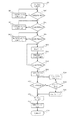
FIG. 8 shows a control flow of the first embodiment. FIG. 12A is a diagram illustrating movement of the moving object in this embodiment. En is a position signal based on the encoder signal. The arrow MV3 is subjected to stop processing after the leading end position of the recording medium conveyed by the conveying means has moved a distance d from the timing of En. As a result, the vehicle stops at the position Pn + 1 (here, for the sake of simplicity, the moving distance is set to 0 until the stop process is performed and the vehicle stops). Then, due to the elastic deformation charging force, it moves by the distance d and stops at the position Pn (arrow MV4).
この処理を図8を用いて説明する。DCモータ駆動開始(s801)後、加速領域内(s802)では、加速領域のパラメータによる位置サーボ(s803)を実施する。加速領域から定速領域に移動したら(s804)、定速領域のパラメータで位置サーボ(s805)を実施する。定速領域から減速領域に移動したら(s806)、減速領域のパラメータで位置サーボ(s807)を実施する。 This process will be described with reference to FIG. After starting the DC motor drive (s801), in the acceleration region (s802), position servo (s803) is performed according to the parameters of the acceleration region. After moving from the acceleration region to the constant velocity region (s804), position servo (s805) is performed with the parameters of the constant velocity region. After moving from the constant speed area to the deceleration area (s806), position servo (s807) is executed with the parameters of the deceleration area.
その後、減速制御領域から目標停止位置近傍の規定された位置に到達したら(s806)、速度サーボ(s808)に切り替り、所定の速度を維持する。ここで、各サーボ制御は、規定されたサーボ周期毎に実施され、サーボ周期に達していない場合にはスルーされる。更に、速度情報を基に目標停止位置からの遅延時間(Delay時間)の演算(s809)を実施する。 After that, when a prescribed position near the target stop position is reached from the deceleration control area (s806), the speed is switched to the speed servo (s808) and the predetermined speed is maintained. Here, each servo control is carried out every prescribed servo cycle, and is bypassed when the servo cycle has not been reached. Further, a delay time from the target stop position (Delay time) is calculated based on the speed information (s809).
ここでの演算は、弾性変形チャージ力により戻る距離(d)と移動速度から距離移動する時間を算出する。この移動速度は、停止位置Pnよりも所定の距離より手前の速度情報を用いる。これにより、動作毎に速度がばらついた場合でも、正確に遅延時間を算出できる。 In this calculation, the distance moving time is calculated from the distance (d) returned by the elastic deformation charging force and the moving speed. As this moving speed, speed information before a predetermined distance from the stop position Pn is used. Thereby, even when the speed varies for each operation, the delay time can be calculated accurately.
遅延(Delay)開始位置である目標とする停止位置Pnに到達(s810)したら、Delay時間を数えるカウンターをスタート(s811)させる。 When the target stop position Pn, which is the delay start position, is reached (s810), a counter for counting the delay time is started (s811).
そして、Delay時間の経過を判定(s812)して、Delay時間が経過していない場合は、目標停止位置に対して所定距離だけ離れた位置Pn+2に到達していないことを判定する(s813)。図12では、位置Pn+2に到達していれば、信号En+1の入力があったかを調べる。 Then, it is determined whether the delay time has elapsed (s812). If the delay time has not elapsed, it is determined that the position Pn + 2 that is a predetermined distance away from the target stop position has not been reached (s813). In FIG. 12, if the position Pn + 2 has been reached, it is checked whether or not the signal En + 1 has been input.
もし、位置Pn+2に到達していなければ(s813でN)、時間カウントの基準クロック信号に伴いDelayカウンターをカウントアップ(s814)する。一方、位置Pn+2に到達していれば(s813でY)、オーバーランしたことを示す信号を出力する(オーバーランしたことを示すフラグを予め決められたメモリ領域に設定しても構わない)(s815)。その後、DCモータにトルクをゼロとする処理を行う(s816)。 If the position Pn + 2 has not been reached (N in s813), the delay counter is counted up (s814) in accordance with the reference clock signal for time counting. On the other hand, if the position Pn + 2 has been reached (Y in s813), a signal indicating overrun is output (a flag indicating overrun may be set in a predetermined memory area) ( s815). Thereafter, the DC motor is subjected to a process for reducing the torque to zero (s816).
なお、Delay時間が経過した場合(s812でY)には、DCモータにトルクをゼロとする処理を行う(s816)。Delayカウンターをリセット(s817)して、制御を終了(s818)する。 When the delay time has elapsed (Y in s812), the DC motor is subjected to a process of setting the torque to zero (s816). The delay counter is reset (s817), and the control is terminated (s818).
図9は、図8の速度サーボ(s808)とDelay時間の演算(s809)を詳細に説明する為のフローチャートである。 FIG. 9 is a flowchart for explaining in detail the speed servo (s808) and delay time calculation (s809) of FIG.
図9では、Delay時間の行う前の最新の速度情報とモータのコギングに基づいた戻り量dを用いてDelay時間を算出している。 In FIG. 9, the delay time is calculated using the latest speed information before the delay time and the return amount d based on the cogging of the motor.
目標停止位置近傍の速度サーボ領域に達したら(s901)、速度情報を取得するタイミングであるか判定(s902)を行う。ディジタルエンコーダーの場合、エンコーダ信号のエッジが発生しないと速度情報を確定できない為、離散的に速度情報が確定する。速度情報の取得タイミングの場合(s902でY)には、速度情報を取得(s903する)。その後、サーボ周期の判定(s904)を実施する。サーボは通常ある定められた間隔(例えば1msec)毎に実施される。 When the speed servo area near the target stop position is reached (s901), it is determined whether it is time to acquire speed information (s902). In the case of a digital encoder, the speed information cannot be determined unless an edge of the encoder signal occurs, and therefore the speed information is determined discretely. In the case of speed information acquisition timing (Y in s902), the speed information is acquired (s903). Thereafter, the servo cycle is determined (s904). The servo is usually performed at a predetermined interval (for example, 1 msec).
このサーボ周期毎に予め取得した最新の速度情報(更新された速度情報)に基づいて、サーボ演算(s905)を行う。このサーボ演算の結果に従ってDCモータのトルク制御信号をコントロールする。その後、コギング位相の判定(s906)を実施する。 Servo calculation (s905) is performed based on the latest speed information (updated speed information) acquired in advance for each servo cycle. The torque control signal of the DC motor is controlled according to the result of this servo calculation. Thereafter, the cogging phase is determined (s906).
コギングの位相判定方法としては、所定の一定速度(低い速度)でサーボ制御を実施し、モータ1周期分の速度情報を位置情報と対応して取得する。取得した位置情報と速度情報から周期的な速度の変動を解析することにより、モータ1周期内でのコギング位相特性がわかり、この情報を基にコギング位相の判定(s906)を実施する。コギング位相の判定(s906)の結果や先の処理で求められている速度情報(s903)により戻り量dを算出する(s907)。 As a cogging phase determination method, servo control is performed at a predetermined constant speed (low speed), and speed information for one motor cycle is acquired in correspondence with position information. By analyzing periodic speed fluctuations from the acquired position information and speed information, the cogging phase characteristics within one motor cycle can be determined, and the cogging phase determination (s906) is performed based on this information. The return amount d is calculated based on the result of the cogging phase determination (s906) and the speed information (s903) obtained in the previous processing (s907).
この戻り量dの算出の方法としては、予めコギング位相についての情報や速度情報に基づく戻り量dについてテーブルを不揮発性メモリに格納し、コギング位相の情報と速度情報から戻り量dについての情報を取得する。もちろん、この他にどちらか一方の情報のみをパラメータとしたテーブルを不揮発性メモリに格納し、戻り量dについての情報を取得しても構わない。その後、Delay時間tを演算(s908)して処理を終了する。この処理の後は、図8のDelay開始位置の判定(s810)へ進む。 As a method of calculating the return amount d, a table is stored in advance in the nonvolatile memory for the return amount d based on the information on the cogging phase and the speed information, and information on the return amount d is obtained from the information on the cogging phase and the speed information. get. Of course, a table using only one of the information as parameters may be stored in the non-volatile memory, and information about the return amount d may be acquired. Thereafter, the delay time t is calculated (s908), and the process is terminated. After this process, the process proceeds to the delay start position determination (s810) in FIG.
なお、コギング位相の判定(s906)については、予め目標停止位置がわかっているので、比較的停止精度が良いシステムでは、モータ駆動を開始する前に行うこともできる。この場合には、図9の制御フローでスキップさせることができる。また、コギングの影響を無視できる場合についても、図9の制御フローでスキップすればよい。 Note that the determination of the cogging phase (s906) can be performed before starting the motor drive in a system with relatively high stop accuracy since the target stop position is known in advance. In this case, it can be skipped in the control flow of FIG. Also, the case where the influence of cogging can be ignored may be skipped in the control flow of FIG.
以上のように、弾性変形チャージ力などのような、停止時に発生する力を考慮して意処理を行うので、停止精度が向上する。 As described above, since the intention processing is performed in consideration of the force generated at the time of stopping such as the elastic deformation charging force, the stopping accuracy is improved.
(第2実施の形態)
図10に第2実施の形態の制御フローを示す。第1の実施の形態での処理を共通する部分は説明を省略し、異なる処理について説明をする。
(Second Embodiment)
FIG. 10 shows a control flow of the second embodiment. The description of the parts common to the processes in the first embodiment will be omitted, and different processes will be described.
DCモータ駆動開始(s801)後、第1の実施の形態で説明したように、速度サーボ処理(s808)までフローに沿って処理がなされる。 After starting the DC motor drive (s801), as described in the first embodiment, the process is performed along the flow until the speed servo process (s808).
s1009では、速度情報とコギング位相情報に基づいて、目標とする停止位置での停止維持トルク(停止位置トルク)の大きさを算出する。この停止維持トルクの大きさは、弾性変形チャージ力などにより移動しようとする力を打ち消す(バランスを取る)程度の微弱なトルク量である。 In s1009, the magnitude of the stop maintenance torque (stop position torque) at the target stop position is calculated based on the speed information and the cogging phase information. The magnitude of the stop maintaining torque is a weak torque amount that cancels out (balances) the force to move due to the elastic deformation charging force or the like.
このトルク量は、目標停止位置での速度およびコギング位相などにより変化する。このため、予め速度情報やコギング位相情報をパラメータとしたトルク量についてのテーブルをメモリ(例えば、不揮発性メモリ)に格納しておく。そして、速度情報やコギング位相の情報に基づいて対応するトルク値をメモリから読み出す。 This amount of torque varies depending on the speed at the target stop position, the cogging phase, and the like. For this reason, a table of torque amounts using speed information and cogging phase information as parameters is stored in advance in a memory (for example, a non-volatile memory). Then, the corresponding torque value is read from the memory based on the speed information and the cogging phase information.
その後、目標停止位置の判定(s1010)を行い、目標停止位置に到達した時、算出した停止維持トルク(停止位置トルク)を出力するように、制御信号をモータ(あるいはモータ制御回路)に出力する。この処理により、所望の停止位置において、弾性変形チャージ力とバランスがとれていれば、停止状態を維持する(所望の停止位置から動かない)。 Thereafter, the target stop position is determined (s1010), and when the target stop position is reached, a control signal is output to the motor (or motor control circuit) so as to output the calculated stop maintenance torque (stop position torque). . By this process, if the elastic deformation charge force is balanced at the desired stop position, the stop state is maintained (does not move from the desired stop position).
そして、所定のタイミングになったことを示す処理終了フラグを確認する(s1012)。この所定のタイミングは、他の動作の終了タイミングや開始タイミングである。具体的な例としては、シリアルタイプのプリンターの搬送手段の停止処理に適用した場合では、キャリッジの主走査動作の停止タイミングであるとか、キャリッジの主走査動作における記録ヘッドのインク吐出の終了タイミングなどがあげられる。 Then, a process end flag indicating that the predetermined timing has been reached is confirmed (s1012). This predetermined timing is the end timing or start timing of another operation. As a specific example, when applied to the stop process of the conveying means of a serial type printer, it is the stop timing of the main scanning operation of the carriage, the end timing of ink ejection of the recording head in the main scanning operation of the carriage, etc. Can be given.
終了フラグが立っていない場合(s1012でN)は、停止状態を維持しているかの確認をする。このために、目標停止位置に対して予め規定されている位置に到達していないの判定(s813)を実施する。これは、第1の実施の形態で示した処理と同じである。 If the end flag is not set (N in s1012), it is confirmed whether the stop state is maintained. For this purpose, it is determined (s813) that the target stop position has not been reached in advance. This is the same as the processing shown in the first embodiment.
つまり、装置の状態によっては、算出した停止維持トルク(停止位置トルク)よりも、弾性変形チャージ力の方が小さい場合、停止状態を維持できず、移動するはずである。この場合、信号信号En+1が入力されるかの処理を行う。 That is, depending on the state of the apparatus, if the elastic deformation charge force is smaller than the calculated stop maintenance torque (stop position torque), the stop state cannot be maintained and the device should move. In this case, it is processed whether the signal signal En + 1 is input.
終了フラグが立っていれば(s1012でN)、DCモータトルクゼロ(s816)に移行する。 If the end flag is set (N in s1012), the process proceeds to zero DC motor torque (s816).
以上説明したように、本実施形態によれば、モータを停止した際、弾性変形チャージ力を打ち消す力を出力し、停止状態を維持することができ、停止精度の向上を実現することが可能になる。 As described above, according to the present embodiment, when the motor is stopped, it is possible to output a force that cancels the elastic deformation charging force, to maintain the stopped state, and to improve the stopping accuracy. Become.
(第3実施の形態)
図12(B)は、第3実施の形態での、移動体の移動を説明する図である。第1実施の形態の動作と異なるのは、目標とする停止位置Pmが、エンコーダーの信号に基づく位置信号EnとEn+1の間に位置している場合である。このため、s809におけるDelay時間の算出内容が異なるだけであるので、図8の制御フローが適用できる。
(Third embodiment)
FIG. 12B is a diagram for explaining the movement of the moving object in the third embodiment. The difference from the operation of the first embodiment is that the target stop position Pm is located between the position signals En and En + 1 based on the encoder signal. For this reason, since the calculation content of the delay time in s809 is different, the control flow of FIG. 8 can be applied.
このDelay時間の算出処理において、所望の停止位置PmとPnの距離d2を求め、この値d2と弾性変形チャージ力により戻る距離dとを加算してd3を求める。 In this delay time calculation process, a distance d2 between desired stop positions Pm and Pn is obtained, and d3 is obtained by adding this value d2 and the distance d returned by the elastic deformation charging force.
このd3を算出することで、矢印MV5で示すように、停止位置Pn+1で停止させることができる。その後、弾性変形チャージ力により矢印MV6に移動し、目標とする停止位置Pmで停止させることができる。 By calculating this d3, it is possible to stop at the stop position Pn + 1 as indicated by the arrow MV5. Then, it can move to arrow MV6 by elastic deformation charge force, and can be stopped at the target stop position Pm.
以上のように、弾性変形チャージ力などのような、停止時に発生する力を考慮したて意処理を行うのことができ、さらに、エンコーダーの信号の解像度より高い解像度で停止させることができるので、停止精度をよりいっそう向上させることができる。 As described above, it is possible to perform intentional processing in consideration of the force generated at the time of stopping, such as elastic deformation charging force, and furthermore, it is possible to stop at a resolution higher than the resolution of the encoder signal. The stopping accuracy can be further improved.
(その他の実施の形態)
なお、弾性変形チャージ力により移動する距離(戻り量)dを補正するための、速度の算出方法として、上述した方法に限定するものではない。例えば、速度サーボの制御パラメータである速度値(速度サーボ領域での目標速度)を用いる。これにより、動作毎に速度のばらつきが小さい場合には、動作毎(例えば、搬送動作毎)に演算を行う必要がないので、モータ制御の負荷を軽減することができる。
(Other embodiments)
Note that the speed calculation method for correcting the distance (return amount) d moved by the elastic deformation charging force is not limited to the method described above. For example, a speed value (target speed in the speed servo area) that is a control parameter of the speed servo is used. As a result, when the variation in speed for each operation is small, it is not necessary to perform calculation for each operation (for example, for each conveyance operation), so that the load of motor control can be reduced.
また、弾性変形チャージ力により移動する距離(戻り量)dは、一定の値として扱っているが、装置の状態に基づいて算出する変数(パラメータ)であっても構わない。例えば、移動体である被記録媒体と搬送路との摩擦係数等の情報によって、弾性変形チャージ力により移動する距離(戻り量)dを算出しても構わない。例えば、搬送手段が搬送する被記録媒体の種類や大きさに基づいて算出する。あるいは、搬送手段のモータや伝達手段(ギヤ)のコギングについての情報による。例えば、コギングの周期や大きさなどが挙げられる。この他、メカ的な周期的な外乱の影響を考慮してもよいし、上述したこれらの要因を組み合わせても構わない。 Further, the distance (return amount) d moved by the elastic deformation charging force is treated as a constant value, but may be a variable (parameter) calculated based on the state of the apparatus. For example, the distance (return amount) d that is moved by the elastic deformation charging force may be calculated based on information such as a friction coefficient between the recording medium that is a moving body and the conveyance path. For example, the calculation is performed based on the type and size of the recording medium conveyed by the conveying unit. Alternatively, it depends on information about the cogging of the motor of the conveying means and the transmitting means (gear). For example, the period and magnitude of cogging can be mentioned. In addition, the influence of mechanical periodic disturbances may be taken into account, or these factors described above may be combined.
なお、記録ヘッドを用いた記録装置において、記録用紙などの被記録媒体を搬送する搬送手段の制御について説明したが、例えば、原稿の画像を読み取るための画像入力装置に適用しても良い。 In the recording apparatus using the recording head, the control of the conveying unit that conveys a recording medium such as recording paper has been described. However, the present invention may be applied to, for example, an image input apparatus for reading an image of a document.
また、被記録媒体の搬送について説明したが、記録装置に限定するものではなく、例えば、検査装置などの電子機器や電子装置において、ステージなどの移動体を移動させる制御に適用しても構わない。 Further, although the conveyance of the recording medium has been described, the present invention is not limited to the recording apparatus, and may be applied to, for example, control for moving a moving body such as a stage in an electronic apparatus or an electronic apparatus such as an inspection apparatus. .
4 搬送ローラ
5 ピンチローラ
6 ピンチローラガイド
7 記録ヘッド
8 プラテン
9 キャリッジ
10 ガイド軸
11 ガイドレール
13 キャリッジモータ
14 タイミングベルト
15 アイドルプーリ
16 電気基板
17 フレキシブルケーブル
18 リニアスケール
19 排紙ローラ
20 排紙ローラギア
25 LFモータ
26 LFエンコーダスケール
27 搬送ローラギア
28 LFエンコーダセンサ
29 LFエンコーダセンホルダ
30 LFタイミングベルト
31 排紙伝達ギア
231 ホストインターフェース
401 プリンタ装置のプリンタ制御用のCPU
402 ROM
403 RAM
405 モータを駆動するモータドライバ
406 プリンタコントローラ
407 サーミスタ等で構成される温度センサ
501 I/Oレジスタ
502 受信バッファコントローラ
503 印刷バッファコントローラ
504 メモリコントローラ
505 プリントシーケンスコントローラ
6001 理想位置プロファイル
6005 エンコーダセンサ
6009 エンコーダ位置情報変換手段
6006 エンコーダ速度情報変換手段
6002 位置サーボのメジャーループ
6003 PI演算
6007 微分演算
6004 DCモータに与えるエネルギー
6008 外乱
7001 理想速度プロファイル
7002 PI演算
7003 微分演算
4 Conveying
402 ROM
403 RAM
405 Motor driver for driving
Claims (7)
前記DCモータからトルクを伝達するトルク伝達部材を含み、前記DCモータから駆動トルクを受けて被駆動体を所定方向に移動させ、前記DCモータのトルクをゼロにする際に前記トルク伝達部材の変形に基づくトルクにより前記被駆動体を前記所定方向と逆向きに移動させる移動手段と、
前記被駆動体の移動に伴って、周期的にパルス信号を出力するエンコーダー手段と、
前記パルス信号の時間間隔に基づき前記被駆動体の速度情報と位置情報を取得する情報取得手段と、
目標停止位置を含む位置プロファイルと前記情報取得手段により取得された前記速度情報と前記位置情報とに基づき、前記DCモータを制御する制御手段と、
前記移動手段による前記逆向きの移動による前記被駆動体の停止位置のずれ量を算出する算出手段と、
前記目標停止位置を通過してから前記DCモータのトルクをゼロにする停止処理を行うべきタイミングを前記ずれ量に基づいて決定する決定手段とを備え、
前記制御手段は、前記決定手段により決定されたタイミングに基づき、前記停止処理を行うことを特徴とするDCモータ制御装置。 A DC motor;
A torque transmission member that transmits torque from the DC motor, and receives the driving torque from the DC motor to move the driven body in a predetermined direction, and when the torque of the DC motor is reduced to zero, the deformation of the torque transmission member Moving means for moving the driven body in a direction opposite to the predetermined direction by a torque based on
Encoder means for periodically outputting a pulse signal as the driven body moves,
Information acquisition means for acquiring speed information and position information of the driven body based on a time interval of the pulse signal;
And control means on the basis of the speed information and position profile containing the target stop position acquired by the information acquisition means and said position information, controls the DC motor,
Calculating means for calculating a deviation amount of the stop position of the driven body due to the reverse movement by the moving means;
Determining means for determining , based on the amount of deviation, a timing at which stop processing for reducing the torque of the DC motor to zero after passing through the target stop position ;
The DC motor control apparatus, wherein the control means performs the stop process based on the timing determined by the determination means .
DCモータと、
前記DCモータからトルクを伝達するトルク伝達部材を含み、前記DCモータから駆動トルクを受けて被記録媒体を所定方向に移動させ、DCモータのトルクをゼロにする際に前記トルク伝達部材の変形に基づくトルクにより前記被記録媒体を前記所定方向と逆向きに移動させる搬送手段と、
前記搬送手段の動作に伴って、周期的にパルス信号を出力するエンコーダー手段と、
前記パルス信号の時間間隔に基づき前記搬送手段の速度情報と位置情報を取得する情報取得手段と、
停止目標位置を含む位置プロファイルと前記情報取得手段により取得された前記速度情報と前記位置情報とに基づき、前記DCモータを制御する制御手段と、
前記搬送手段による前記逆向きの移動による前記被記録媒体の停止位置のずれ量を算出する算出手段と、
前記停止目標位置を通過してから前記DCモータのトルクをゼロにする停止処理を行うべきタイミングを前記ずれ量に基づいて決定する決定手段とを備え、
前記制御手段は、前記決定手段により決定されたタイミングに基づき、前記停止処理を行うことを特徴とする記録装置。 A recording apparatus for recording on a recording medium using a recording head,
A DC motor;
A torque transmission member that transmits torque from the DC motor, receives a driving torque from the DC motor , moves a recording medium in a predetermined direction, and deforms the torque transmission member when the torque of the DC motor is reduced to zero. Conveying means for moving the recording medium in a direction opposite to the predetermined direction by a torque based on ;
Encoder means for periodically outputting a pulse signal in accordance with the operation of the conveying means;
Information acquisition means for acquiring speed information and position information of the transport means based on the time interval of the pulse signal;
Based on the position profile and the velocity information acquired by the information acquisition means including a stop target position and the position information, and control means for controlling the DC motor,
Calculating means for calculating a deviation amount of the stop position of the recording medium due to the reverse movement by the conveying means ;
Determining means for determining , based on the amount of deviation, a timing at which stop processing for reducing the torque of the DC motor to zero after passing the stop target position ;
The recording apparatus according to claim 1, wherein the control unit performs the stop process based on the timing determined by the determination unit.
前記算出手段は、更に、前記被記録媒体と前記搬送路との摩擦係数の情報に基づいて算出することを特徴とする請求項6に記載の記録装置。 The recording apparatus further includes a conveyance path for conveying the recording medium,
The recording apparatus according to claim 6, wherein the calculating unit further calculates information based on information on a coefficient of friction between the recording medium and the conveyance path .
Priority Applications (3)
| Application Number | Priority Date | Filing Date | Title |
|---|---|---|---|
| JP2003372459A JP4447891B2 (en) | 2003-10-31 | 2003-10-31 | DC motor control apparatus and recording apparatus |
| US10/974,717 US7078875B2 (en) | 2003-10-31 | 2004-10-28 | DC motor control apparatus and recording apparatus |
| US11/434,874 US7176649B2 (en) | 2003-10-31 | 2006-05-17 | DC motor control apparatus and recording apparatus |
Applications Claiming Priority (1)
| Application Number | Priority Date | Filing Date | Title |
|---|---|---|---|
| JP2003372459A JP4447891B2 (en) | 2003-10-31 | 2003-10-31 | DC motor control apparatus and recording apparatus |
Publications (3)
| Publication Number | Publication Date |
|---|---|
| JP2005132029A JP2005132029A (en) | 2005-05-26 |
| JP2005132029A5 JP2005132029A5 (en) | 2006-12-14 |
| JP4447891B2 true JP4447891B2 (en) | 2010-04-07 |
Family
ID=34544015
Family Applications (1)
| Application Number | Title | Priority Date | Filing Date |
|---|---|---|---|
| JP2003372459A Expired - Fee Related JP4447891B2 (en) | 2003-10-31 | 2003-10-31 | DC motor control apparatus and recording apparatus |
Country Status (2)
| Country | Link |
|---|---|
| US (2) | US7078875B2 (en) |
| JP (1) | JP4447891B2 (en) |
Families Citing this family (16)
| Publication number | Priority date | Publication date | Assignee | Title |
|---|---|---|---|---|
| JP4552227B2 (en) * | 2005-01-24 | 2010-09-29 | ヤマハ株式会社 | Position detection device |
| JP4470795B2 (en) * | 2005-03-30 | 2010-06-02 | ブラザー工業株式会社 | Image forming apparatus |
| JP4550667B2 (en) * | 2005-05-26 | 2010-09-22 | 船井電機株式会社 | Inkjet printer |
| JP4735081B2 (en) * | 2005-06-30 | 2011-07-27 | ブラザー工業株式会社 | Motor control method, motor control device, and image forming apparatus |
| JP4725252B2 (en) | 2005-08-31 | 2011-07-13 | ブラザー工業株式会社 | Transport device |
| US7762733B2 (en) * | 2006-07-06 | 2010-07-27 | Canon Kabushiki Kaisha | Printing apparatus, conveyance apparatus, and feed-conveyance control method |
| JP5371419B2 (en) * | 2008-12-26 | 2013-12-18 | キヤノン株式会社 | Method for controlling motor in equipment |
| US8833884B2 (en) * | 2011-08-26 | 2014-09-16 | Canon Kabushiki Kaisha | Brushless motor driving apparatus and printing apparatus including brushless motor driving apparatus |
| JP6268459B2 (en) | 2012-02-02 | 2018-01-31 | パナソニックIpマネジメント株式会社 | Motor control device and imaging device |
| JP6126374B2 (en) | 2012-12-18 | 2017-05-10 | キヤノン株式会社 | Recording apparatus and recording control method |
| JP6045453B2 (en) * | 2013-07-19 | 2016-12-14 | キヤノン株式会社 | Motor control device, motor driven device, motor control method, and motor control program |
| US10879819B2 (en) * | 2017-11-02 | 2020-12-29 | Rohm Co., Ltd. | Driving circuit and driving method for DC motor |
| JP7118795B2 (en) * | 2018-08-01 | 2022-08-16 | キヤノン株式会社 | POWER RECEIVING DEVICE, CONTROL METHOD AND PROGRAM THEREOF |
| WO2021124603A1 (en) * | 2019-12-16 | 2021-06-24 | 株式会社日立産機システム | Motor control device and motor control method |
| US11349424B2 (en) * | 2020-01-10 | 2022-05-31 | Steering Solutions Ip Holding Corporation | Observer design for estimating motor velocity of brush electric power steering system |
| CN111660678B (en) * | 2020-06-30 | 2023-11-21 | 厦门汉印电子技术有限公司 | Device and method for detecting rotation amount of printing roller and printer |
Family Cites Families (21)
| Publication number | Priority date | Publication date | Assignee | Title |
|---|---|---|---|---|
| US3882988A (en) * | 1973-08-06 | 1975-05-13 | Bunker Ramo | Mechanism for bi-directionally driving a print head |
| US3950685A (en) * | 1974-04-25 | 1976-04-13 | Lrc, Inc. | Dc motor position controller |
| JPS58151885A (en) * | 1982-03-03 | 1983-09-09 | Hitachi Ltd | Control method for position of motor |
| US4591969A (en) * | 1983-08-11 | 1986-05-27 | International Business Machines Corporation | Microprocessor-controlled positioning system |
| JPH03290706A (en) * | 1990-04-09 | 1991-12-20 | Mitsubishi Electric Corp | Numerical controller |
| US6065830A (en) | 1992-09-18 | 2000-05-23 | Canon Kabushiki Kaisha | Recording apparatus for recording at different recording speeds |
| JP3413028B2 (en) | 1996-10-03 | 2003-06-03 | キヤノン株式会社 | Recording device |
| CA2200247C (en) * | 1996-10-29 | 2004-03-16 | Thomas E. Mccue, Jr. | Z-fold print media handling system |
| US6133706A (en) * | 1997-03-17 | 2000-10-17 | Hewlett-Packard Company | Printer subsystem motion-control sensor apparatus |
| US6350073B1 (en) * | 1999-05-25 | 2002-02-26 | Hewlett-Packard Company | Z-fold print media handling system |
| JP2001169584A (en) * | 1999-09-28 | 2001-06-22 | Seiko Epson Corp | Control device and method for printer motor, and recording medium storing control program |
| JP3501737B2 (en) | 2000-07-19 | 2004-03-02 | キヤノン株式会社 | Encoder signal control circuit and control method of the circuit |
| JP4497703B2 (en) | 2000-10-31 | 2010-07-07 | キヤノン株式会社 | Recording apparatus and recording medium transport mechanism control method |
| JP2002137469A (en) | 2000-10-31 | 2002-05-14 | Canon Inc | Method for controlling sheet member carrier and recorder |
| JP3833060B2 (en) | 2000-10-31 | 2006-10-11 | キヤノン株式会社 | Recording device |
| JP3472278B2 (en) | 2001-05-17 | 2003-12-02 | キヤノン株式会社 | Recording apparatus and recording control method |
| JP3658339B2 (en) | 2001-05-17 | 2005-06-08 | キヤノン株式会社 | Method and apparatus for motor control |
| JP3658340B2 (en) | 2001-05-17 | 2005-06-08 | キヤノン株式会社 | Method and apparatus for motor control |
| DE60230703D1 (en) | 2001-08-27 | 2009-02-26 | Canon Kk | Ink jet printing apparatus and ink jet printing method |
| JP3840081B2 (en) | 2001-10-01 | 2006-11-01 | キヤノン株式会社 | Printing apparatus, drive control method for the apparatus, printing system including the apparatus, and program for executing the method |
| JP3809406B2 (en) | 2002-08-29 | 2006-08-16 | キヤノン株式会社 | Recording apparatus and recording apparatus control method |
-
2003
- 2003-10-31 JP JP2003372459A patent/JP4447891B2/en not_active Expired - Fee Related
-
2004
- 2004-10-28 US US10/974,717 patent/US7078875B2/en not_active Expired - Fee Related
-
2006
- 2006-05-17 US US11/434,874 patent/US7176649B2/en not_active Expired - Fee Related
Also Published As
| Publication number | Publication date |
|---|---|
| US20050093490A1 (en) | 2005-05-05 |
| JP2005132029A (en) | 2005-05-26 |
| US7078875B2 (en) | 2006-07-18 |
| US7176649B2 (en) | 2007-02-13 |
| US20060202655A1 (en) | 2006-09-14 |
Similar Documents
| Publication | Publication Date | Title |
|---|---|---|
| JP4447891B2 (en) | DC motor control apparatus and recording apparatus | |
| US7195239B2 (en) | Printer and paper feed controller | |
| JP5354975B2 (en) | Recording apparatus and conveyance control method | |
| JP4886426B2 (en) | Recording apparatus and conveyance control method | |
| KR100403099B1 (en) | Control method for sheet member conveying apparatus and control method for recording apparatus | |
| US8287088B2 (en) | Image forming apparatus | |
| JP6039329B2 (en) | Recording device | |
| US9925807B2 (en) | Conveyance system, sheet processing system, and controller | |
| US6822411B2 (en) | Method and apparatus for controlling motors | |
| JP2006240212A (en) | Printer and controlling method of motor for printer | |
| JP6390138B2 (en) | Control device | |
| JP5838698B2 (en) | Measuring device and electrical device | |
| JP4484586B2 (en) | Recording apparatus and cueing position control method of recording apparatus | |
| JP5121990B2 (en) | Sheet transport device | |
| JP5125370B2 (en) | Drive control device and drive control method | |
| JP7327026B2 (en) | drive system | |
| US8289569B2 (en) | Encoder signal processor, encoder signal processing method, and transport apparatus | |
| JP5845693B2 (en) | Conveying apparatus and image forming apparatus | |
| JP2006056623A (en) | Image forming device | |
| US20220314666A1 (en) | Control system | |
| JP2006113825A (en) | Driving controller, driving control method and image formation apparatus | |
| JP2023169678A (en) | Electronic apparatus | |
| JP2007196427A (en) | Image forming apparatus | |
| JP2013241249A (en) | Conveyance device and method | |
| JP4721835B2 (en) | Positioning control device and image forming apparatus having the same |
Legal Events
| Date | Code | Title | Description |
|---|---|---|---|
| A521 | Written amendment |
Free format text: JAPANESE INTERMEDIATE CODE: A523 Effective date: 20061031 |
|
| A621 | Written request for application examination |
Free format text: JAPANESE INTERMEDIATE CODE: A621 Effective date: 20061031 |
|
| A131 | Notification of reasons for refusal |
Free format text: JAPANESE INTERMEDIATE CODE: A131 Effective date: 20091020 |
|
| A521 | Written amendment |
Free format text: JAPANESE INTERMEDIATE CODE: A523 Effective date: 20091217 |
|
| TRDD | Decision of grant or rejection written | ||
| A01 | Written decision to grant a patent or to grant a registration (utility model) |
Free format text: JAPANESE INTERMEDIATE CODE: A01 Effective date: 20100119 |
|
| A01 | Written decision to grant a patent or to grant a registration (utility model) |
Free format text: JAPANESE INTERMEDIATE CODE: A01 |
|
| A61 | First payment of annual fees (during grant procedure) |
Free format text: JAPANESE INTERMEDIATE CODE: A61 Effective date: 20100121 |
|
| FPAY | Renewal fee payment (event date is renewal date of database) |
Free format text: PAYMENT UNTIL: 20130129 Year of fee payment: 3 |
|
| R150 | Certificate of patent or registration of utility model |
Free format text: JAPANESE INTERMEDIATE CODE: R150 |
|
| FPAY | Renewal fee payment (event date is renewal date of database) |
Free format text: PAYMENT UNTIL: 20140129 Year of fee payment: 4 |
|
| LAPS | Cancellation because of no payment of annual fees |