JP4484586B2 - Recording apparatus and cueing position control method of recording apparatus - Google Patents
Recording apparatus and cueing position control method of recording apparatus Download PDFInfo
- Publication number
- JP4484586B2 JP4484586B2 JP2004159832A JP2004159832A JP4484586B2 JP 4484586 B2 JP4484586 B2 JP 4484586B2 JP 2004159832 A JP2004159832 A JP 2004159832A JP 2004159832 A JP2004159832 A JP 2004159832A JP 4484586 B2 JP4484586 B2 JP 4484586B2
- Authority
- JP
- Japan
- Prior art keywords
- recording
- roller
- recording medium
- conveyance
- paper
- Prior art date
- Legal status (The legal status is an assumption and is not a legal conclusion. Google has not performed a legal analysis and makes no representation as to the accuracy of the status listed.)
- Active
Links
Images


Description
本発明は記録装置及び記録装置の頭出し位置制御方法に関し、より詳細には、給紙手段と搬送手段それぞれにサーボ制御されるモータを有する記録装置における頭出し位置の制御に関する。 The present invention relates to a recording apparatus and a cueing position control method of the recording apparatus, and more particularly to control of a cueing position in a recording apparatus having a servo-controlled motor for each of a paper feeding unit and a conveying unit.
従来、プリンタ等の記録装置においては、並列動作を可能とするため、あるいはモータへの負荷を分散すると共に高機能、高速化を実現するために、記録媒体の給紙動作と搬送動作とに異なるモータを用いる構成が知られている。 2. Description of the Related Art Conventionally, in a recording apparatus such as a printer, a recording medium feeding operation and a conveying operation are different in order to enable a parallel operation or to distribute a load on a motor and realize a high function and a high speed. A configuration using a motor is known.
また、静音化と高速化の両立のため、駆動音が静かで脱調が生じないDCモータを使用する記録装置が増えている。しかしながら、DCモータは、位置検知手段としてのエンコーダの信号に基づいてフィードバック制御(サーボ制御)する必要があり、DCモータを使用する際にはエンコーダも必要となるため、コスト増となりやすい。 Further, in order to achieve both quietness and high speed, an increasing number of recording apparatuses use a DC motor that has a quiet driving sound and does not step out. However, the DC motor needs to be feedback controlled (servo control) based on the signal of the encoder as the position detection means, and the encoder is also required when using the DC motor, so that the cost tends to increase.
このため、記録中に駆動される時間が比較的長い、キャリッジの駆動や搬送動作にはDCモータを採用するケースが多くなってきたものの、給紙動作に個別のモータを用いる記録装置では、記録中に駆動される時間が比較的短い給紙動作には、パルスモータを使用するのが一般的である。 For this reason, although the driving time during recording is relatively long and a DC motor is often used for driving and conveying operations of the carriage, in a recording apparatus using a separate motor for the paper feeding operation, A pulse motor is generally used for a paper feeding operation in which the driving time is relatively short.
この様な、給紙動作用と搬送動作用とで異なる駆動源(モータ)が設けられている記録装置において、記録開始までの時間を短縮するために、用紙の斜行給紙を矯正するレジ取り動作を省略し、給紙ローラにより送り込まれた用紙をそのまま搬送ローラへ噛み込ませて記録紙の頭出しを行う(以降、レジ無しと称する)と、給紙動作と搬送動作とのつなぎ目が存在する。 In such a recording apparatus provided with different drive sources (motors) for feeding operation and conveying operation, in order to shorten the time until the start of recording, a register for correcting skew feeding of the sheet is used. If the take-up operation is omitted and the paper fed by the paper feed roller is directly bitten into the transport roller to cue the recording paper (hereinafter referred to as “no registration”), the connection between the paper feed operation and the transport operation is Exists.
通常、給紙部の給紙ローラは、用紙をピックアップし、搬送ローラのニップまでの距離よりも長い距離を送れるように設定され、且つ定まった搬送量を有している。一方、搬送ローラの頭出し時の搬送量は、記録する画像パターンに応じて変化する。そのため、レジ無しで頭出しを行なう時に、給紙ローラと搬送ローラとの停止タイミングが等しくならない。レジ無し頭出しにおいて、記録用紙の位置を把握するためには、給紙動作による記録用紙の位置把握から搬送動作による記録用紙の位置把握への切り替えを、頭出し動作中に行わなければならない。 Usually, the paper feed roller of the paper feed unit is set so as to pick up the paper and send a distance longer than the distance to the nip of the transport roller, and has a fixed transport amount. On the other hand, the conveyance amount at the time of cueing of the conveyance roller changes according to the image pattern to be recorded. For this reason, when the cueing is performed without a registration, the stop timings of the paper feed roller and the conveyance roller are not equal. In order to grasp the position of the recording paper in the registration-free cueing, it is necessary to switch from the recording paper position grasping by the paper feeding operation to the recording paper position grasping by the conveying operation during the cueing operation.
一方、レジ取り動作を行う頭出しでは、記録紙のレジ取り動作用のループ終了時に搬送ローラが停止状態にあり、この状態からの搬送ローラの回転量のみで頭出し量が管理可能である。 On the other hand, in the cueing operation in which the registration operation is performed, the conveyance roller is stopped at the end of the recording paper registration operation loop, and the cueing amount can be managed only by the rotation amount of the conveyance roller from this state.
このレジ無し頭出しの方法としては、給紙動作用にパルスモータを採用している場合には、給紙ローラと搬送ローラとの間に用紙位置検知手段を設置し、給紙中の記録用紙先端検知位置から給紙動作用のパルスモータのパルスのカウントを開始し、そのカウント時間が所定の時間に達した時点を基準として、搬送用DCモータのエンコーダの出力から用紙の搬送量を算出する方法が、特開2002−037483号公報(特許文献1)に開示されている。
しかしながら、上記のレジ無し頭出し方法は、給紙動作用としてパルスモータを採用して開ループ制御を行なうものであるが、DCモータを採用してフィードバック制御(サーボ制御)を用いた閉ループ制御を行なう場合にそのまま適用することはできず、レジ無し時の頭出し量の誤差が変動してしまう。 However, the above-described registrationless cueing method employs a pulse motor for paper feeding operation and performs open loop control, but employs a DC motor and performs closed loop control using feedback control (servo control). This cannot be applied as it is, and the error of the cue amount when there is no cash register fluctuates.
そもそも、サーボ制御とは、指令値(理想プロファイル)に追随するように制御を行うものである。このため、給紙動作用と搬送動作用との駆動源として個別の位置検知信号によってサーボ制御される別々のモータを使用する構成では、モータによって駆動される制御対象(用紙)の位置は、理想プロファイルに対して時間的遅れを伴って追随するため、ある時間における理想位置と実際の位置では相違が生じる。更に、メカの負荷変動等の外乱等によっても位置の相違が生じてしまう。 In the first place, the servo control is to perform control so as to follow the command value (ideal profile). For this reason, in a configuration in which separate motors that are servo-controlled by individual position detection signals are used as driving sources for paper feeding operation and conveyance operation, the position of the control target (paper) driven by the motor is ideal. Since the profile follows the profile with a time delay, there is a difference between the ideal position and the actual position at a certain time. Further, the difference in position also occurs due to disturbances such as mechanical load fluctuations.
従って、パルスモータに適用していた頭出し処理を、そのままサーボ制御されるモータ(DCモータ)に適用すると、上述の想定位置と実際の位置との相違(ズレ)がそのまま頭出し量のズレとなり、記録開始位置がズレてしまう。 Therefore, if the cue processing applied to the pulse motor is applied to a servo-controlled motor (DC motor) as it is, the difference (deviation) between the above-mentioned assumed position and the actual position becomes the deviation of the cue amount as it is. The recording start position is misaligned.
つまり、給紙モータの搬送量を時間によって管理しているため、給紙モータに速度変動が生じると、位置ズレが発生してしまう。 That is, since the conveyance amount of the paper feed motor is managed by time, if the speed fluctuation occurs in the paper feed motor, a positional deviation occurs.
更に、記録装置を大量生産すると、部品の公差や製造工程での誤差に起因して個々の製品間でのバラツキがある程度発生するが、この頭出し量も例外ではなく個々の製品間で多少のバラツキが発生してしまう。しかしながら、このバラツキを抑制する試みはなされてこなかった。 In addition, mass production of recording devices causes some variation between individual products due to part tolerances and manufacturing process errors, but this cue amount is not an exception and is somewhat different between individual products. Variation will occur. However, no attempt has been made to suppress this variation.
本発明は以上のような状況に鑑みてなされたものであり、給紙用と搬送用とに別個のサーボモータを有し、各モータをサーボ制御する記録装置において、レジ取り動作を行わないで記録する場合においても、頭出し量のバラツキを抑制し、記録開始位置を正確に制御することを目的とする。 The present invention has been made in view of the situation as described above. In the recording apparatus that has separate servo motors for paper feeding and conveyance and servo-controls each motor, the registration operation is not performed. Even in the case of recording, it is an object to suppress variations in the cueing amount and accurately control the recording start position.
上記目的を達成するため本発明の一態様としての記録装置は、複数枚の記録媒体を積載する積載手段と、
給紙ローラ、及び前記給紙ローラを駆動し、前記給紙ローラの回転量に基づいてサーボ制御される給紙モータを有し、前記積載手段に積載された記録媒体を1枚ずつピックアップして前記給紙ローラによって給紙する給紙手段と、
搬送ローラ、該搬送ローラに対向して設けられたピンチローラ、及び前記搬送ローラを駆動し、前記搬送ローラの回転量に基づいてサーボ制御される搬送モータを有し、前記給紙手段によって給紙された記録媒体を前記搬送ローラと前記ピンチローラとで狭持して記録領域に搬送する搬送手段と、
前記積載手段から前記搬送手段までの搬送経路に設けられ、記録媒体の先端の通過を検出する先端検出手段と、
前記先端検出手段によって記録媒体の先端が検出される位置から所定位置までの記録媒体の第1の搬送距離を、前記給紙ローラの回転量に基づいて制御し、前記所定位置から前記記録領域の記録開始位置までの記録媒体の第2の搬送距離を、前記搬送ローラの回転量に基づいて制御することで、前記先端検出手段によって記録媒体の先端が検出される位置から前記記録開始位置までの記録媒体の搬送を連続して行う制御手段と
を備え、
前記所定位置は、
前記先端検出手段によって記録媒体の先端が検出される位置と前記記録領域との間の搬送経路に定められ、記録媒体が前記搬送ローラと前記ピンチローラとによって狭持されるニップ位置もしくは前記ニップ位置の前記記録領域側に定められていることを特徴とする。
In order to achieve the above object, a recording apparatus as one aspect of the present invention includes a stacking unit that stacks a plurality of recording media,
A paper feed roller, and a paper feed motor that drives the paper feed roller and is servo-controlled based on the rotation amount of the paper feed roller, and picks up the recording media stacked on the stacking means one by one A paper feed means for feeding paper by the paper feed roller;
A conveyance roller, a pinch roller provided opposite to the conveyance roller, and a conveyance motor that drives the conveyance roller and is servo-controlled based on a rotation amount of the conveyance roller , and feeds paper by the paper feeding unit Conveying means for nipping the recorded recording medium between the conveying roller and the pinch roller and conveying the recording medium to a recording area;
A leading edge detecting means provided in a conveying path from the stacking means to the conveying means, for detecting passage of the leading edge of the recording medium;
A first conveying distance of the recording medium from the position where the tip is discovered in the recording medium by said front edge detecting means to a predetermined position, and the control based on the rotation amount of the feed roller, from the predetermined position of the recording area By controlling the second conveyance distance of the recording medium to the recording start position based on the rotation amount of the conveyance roller, the position from the position where the leading edge of the recording medium is detected by the leading edge detection unit to the recording start position is determined. and a control means for conveying the recording medium in succession,
The predetermined position is
A nip position or a nip position, which is defined in a conveyance path between a position where the leading edge of the recording medium is detected by the leading edge detection means and the recording area, and is nipped by the conveyance roller and the pinch roller Is defined on the recording area side .
上記目的を達成する本発明の別の態様としての記録層h紙の頭出し位置制御方法は、複数枚の記録媒体を積載する積載手段と、給紙ローラ、及び前記給紙ローラを駆動し、前記給紙ローラの回転量に基づいてサーボ制御される給紙モータを有し、前記積載手段に積載された記録媒体を1枚ずつピックアップして前記給紙ローラによって給紙する給紙手段と、搬送ローラ、該搬送ローラに対向して設けられたピンチローラ、及び前記搬送ローラを駆動し、前記給紙ローラの回転量に基づいてサーボ制御される搬送モータを有し、前記給紙手段によって給紙された記録媒体を前記搬送ローラと前記ピンチローラとで狭持して記録領域に搬送する搬送手段と、前記積載手段から前記搬送手段までの搬送経路に設けられ、記録媒体の先端の通過を検出する先端検出手段と、を備える記録装置の頭出し位置制御方法であって、
前記先端検出手段によって記録媒体の先端が検出される位置から所定位置までの記録媒体の第1の搬送距離を、前記給紙ローラの回転量に基づいて制御する第1搬送距離制御工程と、
前記所定位置から前記記録領域の記録開始位置までの記録媒体の第2の搬送距離を、前記搬送ローラの回転量に基づいて制御することで、前記先端検出手段によって記録媒体の先端が検出される位置から前記記録開始位置までの記録媒体の搬送を連続して行う第2搬送距離制御工程とを有し、
前記所定位置は、
前記先端検出手段によって記録媒体の先端が検出される位置と前記記録領域との間の搬送経路に定められ、記録媒体が前記搬送ローラと前記ピンチローラとによって狭持されるニップ位置もしくは前記ニップ位置の前記記録領域側に定められていることを特徴とする。
The recording layer h paper cueing position control method as another aspect of the present invention that achieves the above object comprises driving a stacking means for stacking a plurality of recording media, a paper feed roller, and the paper feed roller, A paper feed motor that is servo-controlled based on the rotation amount of the paper feed roller, and picks up recording media stacked on the stacking means one by one and feeds the recording medium by the paper feed roller; A conveyance roller, a pinch roller provided opposite to the conveyance roller, and a conveyance motor that drives the conveyance roller and is servo-controlled based on the rotation amount of the paper supply roller, and is supplied by the paper supply unit. A conveying means for nipping the paper-recorded recording medium between the conveying roller and the pinch roller and conveying the recording medium to a recording area, and a conveying path from the stacking means to the conveying means are provided to pass the leading edge of the recording medium. detection A front end detecting unit that provides a cue position control method for a recording apparatus provided with,
A first conveying distance control step of controlling based on the first conveyance distance of the recording medium from the position where the tip is discovered in the recording medium to a predetermined position, the rotation amount of the paper feed roller by said front edge detecting means,
By controlling the second conveyance distance of the recording medium from the predetermined position to the recording start position of the recording area based on the rotation amount of the conveyance roller, the leading edge of the recording medium is detected by the leading edge detection unit. second possess a conveying distance control step of performing the position continuously conveying the recording medium to the recording start position,
The predetermined position is
A nip position or a nip position that is defined in a conveyance path between a position where the leading edge of the recording medium is detected by the leading edge detection means and the recording area, and the recording medium is nipped by the conveyance roller and the pinch roller Is defined on the recording area side.
このようにすると、第1の搬送距離及び第2の搬送距離のいずれもが、ローラの回転量のみに基づいて制御されるので、速度や時間に基づいて制御する場合に比べてモータの速度変動などの影響を受けずに記録媒体の記録開始位置を制御することが可能である。 In this case, since both the first transport distance and the second transport distance are controlled based only on the rotation amount of the roller, the speed fluctuation of the motor is compared with the case where the control is performed based on the speed and time. It is possible to control the recording start position of the recording medium without being affected by the above.
従って、レジ取り動作を行わない場合においても、搬送ローラによる搬送量の変動を抑制し、記録開始位置を正確に制御することができる。 Therefore, even when the registration operation is not performed, it is possible to suppress the variation in the conveyance amount by the conveyance roller and accurately control the recording start position.
なお、所定位置は、記録領域までの搬送経路において、記録媒体が搬送ローラとピンチローラとによって狭持され始めるニップ位置以降であるのがよい。 The predetermined position may be after the nip position where the recording medium starts to be nipped by the conveyance roller and the pinch roller in the conveyance path to the recording area.
第1の搬送距離及び第2の搬送距離の少なくともいずれか一方を、入力された補正値に応じて変更可能に構成してもよい。この場合、補正値を、所定のテストパターンの記録結果から求めるようにするのがよい。また、補正値を格納する不揮発性の記憶手段を備えるのが好ましい。 You may comprise so that at least any one of a 1st conveyance distance and a 2nd conveyance distance can be changed according to the inputted correction value. In this case, the correction value is preferably obtained from the recording result of a predetermined test pattern. Moreover, it is preferable to provide a non-volatile storage means for storing the correction value.
給紙モータ及び搬送モータとしては、DCモータを用いるのがよい。 A DC motor is preferably used as the paper feed motor and the transport motor.
また、上記目的は上記の記録装置の頭出し位置制御方法をコンピュータ装置によって実行させるコンピュータプログラム、該プログラムを記憶する記憶媒体によっても達成される。 The above object can also be achieved by a computer program that causes a computer apparatus to execute the cueing position control method of the recording apparatus, and a storage medium that stores the program.
本発明によれば、第1の搬送距離及び第2の搬送距離のいずれもが、ローラの回転量のみに基づいて制御されるので、速度や時間に基づいて制御する場合に比べてモータの速度変動などの影響を受けずに記録媒体の記録開始位置を制御することが可能である。 According to the present invention, since both the first transport distance and the second transport distance are controlled based only on the rotation amount of the roller, the speed of the motor is compared with the case where the control is performed based on the speed and time. It is possible to control the recording start position of the recording medium without being affected by fluctuations.
従って、レジ取り動作を行わない場合においても、搬送ローラによる搬送量の変動を抑制し、記録開始位置を正確に制御することができる。 Therefore, even when the registration operation is not performed, it is possible to suppress the variation in the conveyance amount by the conveyance roller and accurately control the recording start position.
以下に、添付図面を参照して、本発明の好適な実施の形態を例示的に詳しく説明する。ただし、以下の実施形態に記載されている構成要素はあくまで例示であり、本発明の範囲をそれらのみに限定する趣旨のものではない。 Hereinafter, exemplary embodiments of the present invention will be described in detail with reference to the accompanying drawings. However, the components described in the following embodiments are merely examples, and are not intended to limit the scope of the present invention only to them.
なお、この明細書において、「記録」(「プリント」という場合もある)とは、文字、図形等有意の情報を形成する場合のみならず、有意無意を問わず、また人間が視覚で知覚し得るように顕在化したものであるか否かを問わず、広く記録媒体上に画像、模様、パターン等を形成する、または媒体の加工を行う場合も表すものとする。 In this specification, “recording” (sometimes referred to as “printing”) is not only for forming significant information such as characters and figures, but also for human beings visually perceived regardless of significance. Regardless of whether or not it has been manifested, it also represents a case where an image, a pattern, a pattern, or the like is widely formed on a recording medium or the medium is processed.
また、「記録媒体」とは、一般的な記録装置で用いられる記録用紙のみならず、広く、布、プラスチック・フィルム、金属板、ガラス、セラミックス、木材、皮革等、インクを受容可能なものも表すものとする。 The “recording medium” includes not only recording paper used in general recording apparatuses but also a wide range of materials that can accept ink, such as cloth, plastic film, metal plate, glass, ceramics, wood, leather, etc. It shall represent.
更に、本明細書において、「エンコーダ」とは、モータ等によって駆動される機構部分の回転量又は移動量を検知するものであり、モータ又はそれによって駆動される機構部分に取り付けられたパターンと、該パターンを検知するセンサとで構成され、機構部分の所定量の回転又は移動の度に例えばパルス状の信号(パルス信号)がセンサから出力され、該信号をカウントすることで機構部分あるいは被駆動体の回転量や移動量を算出可能に構成されたものであり、パターンの形状やセンサの検知方法、出力信号の形状は特に問わない。なお、明細書中において、「エンコーダの出力(信号)」とはセンサからの出力(信号)を意味する。 Furthermore, in the present specification, the “encoder” detects the amount of rotation or movement of a mechanism portion driven by a motor or the like, and a pattern attached to the motor or the mechanism portion driven by the motor, A sensor that detects the pattern, for example, a pulse signal (pulse signal) is output from the sensor each time a predetermined amount of rotation or movement of the mechanism part, and the mechanism part or driven is counted by counting the signal. The rotation amount and the movement amount of the body can be calculated, and the shape of the pattern, the detection method of the sensor, and the shape of the output signal are not particularly limited. In the specification, “an encoder output (signal)” means an output (signal) from a sensor.
以下に説明する実施形態では、インクジェット記録方式を用いた記録装置を例に挙げて説明する。 In the embodiments described below, a recording apparatus using an inkjet recording method will be described as an example.
<第1の実施形態>
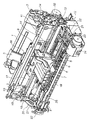
図1は、本発明に係る記録装置の第1の実施形態としての記録装置のカバーを外した状態を示す斜視図であり、図2は図1を裏側から見た斜視図、図3は用紙搬送系を示す側面図である。
<First Embodiment>
FIG. 1 is a perspective view showing a state where a cover of a recording apparatus as a first embodiment of the recording apparatus according to the present invention is removed, FIG. 2 is a perspective view of FIG. 1 viewed from the back side, and FIG. It is a side view which shows a conveyance system.
本実施形態のプリンタは、(A)自動給紙部、(B)送紙部、(C)排紙部、(D)キャリッジ部、(E)クリーニング部から構成される。そこで、これら各部について概略を順次述べる。 The printer according to this embodiment includes (A) an automatic paper feeding unit, (B) a paper feeding unit, (C) a paper discharge unit, (D) a carriage unit, and (E) a cleaning unit. Therefore, the outline of each of these parts will be sequentially described.
(A)自動給紙部
自動給紙部は、記録用紙を積載する圧板1と、記録用紙を給紙する給紙ローラ33がベース2に取り付けられた構成を有する。圧板1には、可動サイドガイド3が移動可能に設けられて、記録用紙の積載位置を規制している。圧板1はベース2に結合された軸を中心に回転可能で、圧板バネ(不図示)により給紙ローラ33に付勢される。
(A) Automatic Paper Feed Unit The automatic paper feed unit has a configuration in which a pressure plate 1 for stacking recording paper and a
記録用紙は、DCモータである給紙モータ32の駆動力により、給紙ローラ33と分離ローラ(不図示)から構成されるニップ部に搬送される。送られた記録用紙はこのニップ部で分離され、最上位の記録用紙Pのみが搬送される。ここで、給紙エンコーダセンサ35により給紙ローラ33の伝達ギアに固定された給紙エンコーダスケール34のライン数を読み取ることで得られる給紙ローラ33の回転量(速度)情報に基づいてフィードバック制御を行い、DCモータである給紙モータ32を回転制御する。このために、給紙エンコーダスケール34のライン数をカウントするカウント手段が設けられている。
The recording paper is conveyed to a nip portion composed of a
(B)送紙部
送紙部は、記録用紙を搬送する搬送ローラ4と用紙端部位置検知センサ36を有している。搬送ローラ4には従動するピンチローラ5が当接して設けられている。ピンチローラ5はピンチローラガイド6に保持され、ピンチローラバネ(不図示)で付勢されることで搬送ローラ4に圧接され、それによって記録用紙の搬送力を生み出している。さらに、搬送ローラ4の記録紙搬送方向における下流側には、画像情報に基づいて画像を形成する記録ヘッドカートリッジ7が設けられている。(以降、搬送をLF(ラインフィード)とも呼ぶ。)
搬送エンコーダセンサ28が搬送エンコーダセンサホルダ29に固定され、これがシャーシ12に取り付けられている。また、搬送モータ25の駆動力は搬送タイミングベルト30を介して搬送ローラ4に圧入固定された搬送ローラギア27に伝達される。この搬送エンコーダセンサ28により搬送ローラ4に挿入され搬送ローラギア27に固定された搬送エンコーダスケール26のライン数を読み取ることで得られる搬送ローラ4の回転量(速度)情報に基づいてフィードバック制御を行い、DCモータである搬送モータ25を回転制御して記録用紙が搬送される。このために、搬送エンコーダスケール26のライン数をカウントするカウント手段が設けられている。送紙部に送られた記録用紙は、ピンチローラガイド6およびペーパーガイド37(図1,2には不図示)に案内されて、搬送ローラ4とピンチローラ5とのローラ対に送られる。また、記録時には、記録用紙はローラ対4、5が回転することで、プラテン8上を搬送される。
(B) Paper Feed Unit The paper feed unit has a transport roller 4 for transporting the recording paper and a paper edge
The
(C)キャリッジ部
キャリッジ部は、記録ヘッドカートリッジ7を着脱可能に搭載するキャリッジ9を有している。そしてキャリッジ9は、記録用紙の搬送方向と交差する方向に往復走査させるためのガイド軸10およびキャリッジ9の上部後端を保持して記録ヘッドカートリッジ7と記録用紙との隙間を維持するガイドレール11によって支持されている。なお、これらガイド軸10およびガイドレール11は、シャーシ12に取り付けられている。
(C) Carriage part The carriage part has a
キャリッジ9は、シャーシ12に取り付けられたDCモータであるキャリッジモータ13によってタイミングベルト14を介して駆動される。このタイミングベルト14は、アイドルプーリ15によって張設、支持されている。さらに、キャリッジ9には、電気基板16から記録ヘッドカートリッジ7へヘッド信号を伝えるためのフレキシブルケーブル17が備えられている。また、キャリッジ9にはキャリッジの位置を検知するリニアエンコーダ(不図示)が搭載されており、シャーシ12に取り付けられたリニアスケール18のライン数を読みとることにより、キャリッジ9の位置を検知することができる。このリニアエンコーダ18の信号は、フレキシブルケーブル17を介して、電気基板16に伝えられ処理される。
The
上記の構成において、記録用紙に画像を形成する際には、画像形成する行位置(記録用紙の搬送方向の位置)に搬送ローラ対4、5により記録用紙を搬送するとともに、キャリッジモータ13と、リニアエンコーダを使用したフィードバック制御により、キャリッジ9を画像形成する列位置(記録用紙の搬送方向と交差する位置)に移動させて、記録ヘッドカートリッジ7を画像形成位置に対向させる。その後、電気基板16からの信号により、記録ヘッドカートリッジ7が記録用紙に向けてインクを吐出して画像が形成される。
In the above configuration, when an image is formed on the recording sheet, the recording sheet is conveyed by the conveying roller pairs 4 and 5 to the row position (position in the conveying direction of the recording sheet) where the image is formed, and the
(D)排紙部
排紙部は、排紙ローラ19に従動して回転可能なように拍車(不図示)が排紙ローラ19に当接されている。排紙ローラ19には、搬送ローラギア27からの駆動が排紙伝達ギア31、排紙ローラギア20を介して伝達される。以上の構成によって、駆動されキャリッジ部で画像形成された記録用紙は、排紙ローラ19と拍車とのニップに挟まれて搬送され、不図示の排紙トレー等に排出される。
(D) Paper Discharge Unit A spur (not shown) is in contact with the
(E)クリーニング部
クリーニング部は、記録ヘッドカートリッジ7の各ノズル(吐出口)に至るまでの経路のクリーニングを行なうポンプ24と、記録ヘッドカートリッジ7の乾燥を抑えるためのキャップ21、記録ヘッドカートリッジ7のフェイス面を清掃するワイパー22、および駆動源であるPGモータ23から構成されている。
(E) Cleaning unit The cleaning unit includes a
(制御構成)
図4は、電気基板16上に構成されたプリンタの制御構成を説明するブロック図である。
(Control configuration)
FIG. 4 is a block diagram illustrating a control configuration of the printer configured on the
同図において、401はプリンタ装置のプリンタ制御用のCPUで、ROM402に記憶されたプリンタ制御プログラムやプリンタエミュレーション、記録フォントを利用して印刷処理を制御する。
In the figure,
403はRAMで、記録のための展開データ、ホストからの受信データを蓄える。404は記録ヘッド(前述の記録ヘッドカートリッジ7の記録ヘッドをブロックで表現)、405はモータを駆動するモータドライバ、406はプリンタコントローラで、RAM403のアクセス制御やホスト装置とのデータのやりとりやモータドライバへの制御信号送出を行う。407はサーミスタ等で構成される温度センサで、プリンタ装置の温度を検知する。
A
CPU401はROM402内の制御プログラムにより本体のメカ的/電気的制御を行いつつ、ホスト装置からプリンタ装置へ送られてくるエミュレーションコマンド等の情報をプリンタコントローラ406内のI/Oデータレジスタから読み出し、コマンドに対応した制御をプリンタコントローラ406内のI/Oレジスタ、I/Oポートに書き込み、読み出しを行う。
The
(位置サーボ系)
図5は一般的なDCモータの位置制御系を説明する模式図であり、位置サーボをかける場合の手法について示している。ここでは、代表例として搬送モータ(LFモータとも呼ぶ)に対する位置サーボについて述べるが、給紙モータ32に対する制御も同様である。
(Position servo system)
FIG. 5 is a schematic diagram for explaining a position control system of a general DC motor, and shows a method for applying position servo. Here, as a representative example, a position servo for a conveyance motor (also referred to as an LF motor) will be described, but the control for the
本実施形態装置において位置サーボは、加速制御領域、定速制御領域、減速制御領域において使用される。DCモータは、PIDコントロールあるいは古典制御と呼ばれる手法で制御されており、以下その手順を説明する。 In the present embodiment, the position servo is used in the acceleration control region, the constant speed control region, and the deceleration control region. The DC motor is controlled by a technique called PID control or classical control, and the procedure will be described below.
まず、制御対象に与えたい目標位置は、6001の理想位置プロファイルという形で与える。本実施形態の装置においては、これは該当する時刻においてLFモータによって搬送された記録用紙が到達しているべき絶対位置に該当する。時刻の進行とともに、この位置情報は変化していく。この理想位置プロファイルに対して追値制御を行うことで、本実施形態の装置の駆動は遂行される。 First, the target position to be given to the control object is given in the form of an ideal position profile 6001. In the apparatus of the present embodiment, this corresponds to the absolute position where the recording sheet conveyed by the LF motor should reach at the corresponding time. This position information changes as time progresses. By performing additional value control on the ideal position profile, the apparatus of the present embodiment is driven.
装置には6005のエンコーダセンサが具備されており、モータの物理的な回転を検知する。6009のエンコーダ位置情報変換手段は、エンコーダセンサが検知したスリット数を加算していき絶対位置情報を得る手段であり、6006のエンコーダ速度情報変換手段はエンコーダセンサの信号と、プリンタに内蔵された時計から、現在のLFモータの駆動速度を算出する手段である。
The device is equipped with 6005 encoder sensors to detect the physical rotation of the motor. The encoder position
6001の理想位置プロファイルから、6009の位置情報変換手段により得られた実際の物理的位置を減算した数値を、目標位置に対して足りない位置誤差として、6002以降の位置サーボのフィードバック処理に受け渡す。6002は位置サーボのメジャーループであり、一般的には比例項Pに関する計算を行う手段が知られている。
A numerical value obtained by subtracting the actual physical position obtained by the position information conversion means 6009 from the ideal position profile 6001 is transferred to the position
6002における演算の結果としては、速度指令値が出力される。この速度指令値が、6003以降の速度サーボのフィードバック処理に受け渡される。速度サーボのマイナーループは、比例項P、積分項I、微分項Dに対する演算を行うPID演算により行う手段が一般的である。 As a result of the calculation in 6002, a speed command value is output. This speed command value is passed to 6003 and subsequent speed servo feedback processes. The minor loop of the speed servo is generally a means that performs a PID calculation for calculating the proportional term P, the integral term I, and the differential term D.
本実施形態の装置においては、速度指令値の非線形な変化が発生した場合の追従性を改善し、なおかつ追値制御時の微分演算の弊害を防ぐために、一般に微分先行形と呼ばれる手法を示しており、6006で得られたエンコーダ速度情報は、6002で得られた速度指令値との差を取る前に、6007の微分演算を通される。この手法自体は本発案の主題となるものではなく、制御対象の系の特性によっては、6003において該微分演算を行えば充分なものもある。 In the apparatus of the present embodiment, in order to improve the followability when a nonlinear change in the speed command value occurs and to prevent the adverse effect of the differential operation during the follow-up control, a method generally called a differential leading form is shown. The encoder speed information obtained in 6006 is subjected to a differential operation in 6007 before taking the difference from the speed command value obtained in 6002. This method itself is not the subject of the present invention, and depending on the characteristics of the system to be controlled, it may be sufficient to perform the differential operation in 6003.
速度サーボのマイナーループにおいては、速度指令値からエンコーダ速度情報を減算した数値を、目標速度に対して足りない速度誤差として、6003のPI演算回路に受け渡し、その時点でDCモータに与えるべきエネルギーを、PI演算と呼ばれる手法で算出する。それを受けたモータドライバ回路は、例えばモータ印加電圧は一定として、印加電圧のパルス幅を変化させる手段(以下「PWM(Pules Width Modulation)制御」と呼ぶ)を用い、印加電圧のDutyを変化させて、電流値を調節し、6004のDCモータに与えるエネルギーを調節し、速度制御を行う。
In the minor loop of the speed servo, the numerical value obtained by subtracting the encoder speed information from the speed command value is passed to the
電流値を印加されて回転するDCモータは、6008の外乱による影響を受けながら物理的な回転を行い、その出力が6005のエンコーダセンサにより検知される。
The DC motor that rotates by being applied with a current value performs physical rotation while being affected by
(速度サーボ系)
図6は一般的なDCモータの速度制御系を説明する模式図であり、速度サーボをかける場合の手法について示している。本実施形態の装置において速度サーボは、位置決め制御領域において使用される。DCモータは、PIDコントロールあるいは古典制御と呼ばれる手法で制御されており、以下その手順を説明する。
(Speed servo system)
FIG. 6 is a schematic diagram for explaining a speed control system of a general DC motor, and shows a method for applying speed servo. In the apparatus of this embodiment, the speed servo is used in the positioning control area. The DC motor is controlled by a technique called PID control or classical control, and the procedure will be described below.
まず、制御対象に与えたい目標速度は、7001の理想速度プロファイルという形で与える。本実施形態の装置においては、これは該当する時刻においてLFモータにより記録用紙を搬送すべき理想速度であり、該当する時刻における速度指令値ということになる。時刻の進行とともに、この速度情報は変化していく。この理想速度プロファイルに対して追値制御を行うことで、本実施形態の装置の駆動は遂行される。 First, the target speed desired to be given to the controlled object is given in the form of 7001 ideal speed profile. In the apparatus of this embodiment, this is the ideal speed at which the recording paper should be conveyed by the LF motor at the corresponding time, and is the speed command value at the corresponding time. As time progresses, this speed information changes. By performing additional value control on this ideal speed profile, the apparatus of this embodiment is driven.
速度サーボにおいては、比例項P、積分項I、微分項Dに対する演算を行うPID演算により行う手段が一般的である。本実施形態の装置においては、速度指令値の非線形な変化が発生した場合の追従性を改善し、なおかつ追値制御時の微分演算の弊害を防ぐために、一般に微分先行形と呼ばれる手法を示しており、6006で得られたエンコーダ速度情報は、7001で得られた速度指令値との差を取る前に、7003の微分演算を通される。この手法自体は本発明の主題となるものではなく、制御対象の系の特性によっては、7002において該微分演算を行えば充分なものもある。 In the speed servo, a means for performing a PID calculation for calculating a proportional term P, an integral term I, and a differential term D is generally used. In the apparatus of the present embodiment, in order to improve the followability when a nonlinear change in the speed command value occurs and to prevent the adverse effect of the differential operation during the follow-up control, a method generally called a differential leading form is shown. The encoder speed information obtained in 6006 is subjected to a differential operation in 7003 before taking the difference from the speed command value obtained in 7001. This method itself is not the subject of the present invention, and depending on the characteristics of the system to be controlled, it may be sufficient to perform the differential operation in 7002.
速度サーボにおいては、速度指令値からエンコーダ速度情報を減算した数値を、目標速度に対して足りない速度誤差として、7002のPI演算回路に受け渡し、その時点でDCモータに与えるべきエネルギーを、PI演算と呼ばれる手法で算出する。それを受けたモータドライバ回路は、例えばPWM制御を用い、印加電圧のDutyを変化させて、電流値を調節し、6004のDCモータに与えるエネルギーを調節し、速度制御を行う。
In the speed servo, the numerical value obtained by subtracting the encoder speed information from the speed command value is passed to the
電流値を印加されて回転するDCモータは、6008の外乱による影響を受けながら物理的な回転を行い、その出力が6005のエンコーダセンサにより検知される。
The DC motor that rotates by being applied with a current value performs physical rotation while being affected by
(頭出し動作)
以下、上記で説明したような構成における記録用紙の頭出し動作について説明する。
(Cue operation)
In the following, the recording paper cueing operation in the configuration as described above will be described.
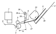
図7は、本実施形態における頭出し動作のフローチャートであり、図8Aから8Dは、各動作状態を説明する図であり。図8Aは初期状態を示している。図8Aから8Dにおいて、各部品形状は簡略化して表現しており、図1から3と同じ部分には同じ参照符号で示している。 FIG. 7 is a flowchart of the cueing operation in the present embodiment, and FIGS. 8A to 8D are diagrams for explaining each operation state. FIG. 8A shows an initial state. 8A to 8D, each part shape is expressed in a simplified manner, and the same parts as those in FIGS. 1 to 3 are denoted by the same reference numerals.
主要な部分について再度説明すると、33は給紙ローラであり、給紙エンコーダ(35:この図では不図示)からの位置信号に基づいて駆動される給紙モータ(32:この図では不図示)によって回転される。給紙ローラ33の回転量すなわち、給紙ローラ33により搬送される記録用紙Pの移動量は、給紙エンコーダセンサの位置信号(パルスカウント数)により検知される。4は搬送ローラであり、搬送エンコーダセンサ(28:この図では不図示)からの位置信号に基づいて駆動される搬送モータ(25:この図では不図示)によって回転される。搬送ローラ4の回転量すなわち、搬送ローラ4により搬送される記録用紙Pの移動量は、搬送エンコーダセンサから出力されるパルス状の位置信号のカウント数により検知される。
The main portion will be described again.
図8Aに示す初期状態において、ホストから記録命令を受信すると、給紙ローラの駆動を開始し(ステップS1001)、最上部の記録用紙Pをピックアップする。 In the initial state shown in FIG. 8A, when a recording command is received from the host, the driving of the paper feed roller is started (step S1001), and the uppermost recording paper P is picked up.
用紙スタック39から分離された記録用紙Pは、給紙ローラ33の回転により搬送され、用紙先端が用紙端部位置検知センサ36により検知される。用紙位置検知センサ36はフォトインタラプタ型のセンサであり、その受光スリット36−aを初期状態で遮蔽していた用紙位置検知レバー38が用紙の先端により押されて回動し、図8Bに示すように、受光スリット36−aが透過状態になった時点で記録用紙の先端が検知される(ステップS1002)。
The recording paper P separated from the
この時点を基準として給紙エンコーダ35からの位置信号により給紙ローラの回転量すなわち記録用紙Pの移動量のカウントを開始する(ステップS1003)。また、この記録用紙先端検知位置から、搬送ローラ4とピンチローラ5のニップまでの距離をLPとする。このLPは定数で、設計上の値もしくは製品の測定により予め求められている。
With this position as a reference, counting of the rotation amount of the paper feed roller, that is, the movement amount of the recording paper P is started by a position signal from the paper feed encoder 35 (step S1003). The distance from the recording paper leading edge detection position to the nip between the conveying roller 4 and the
更に、記録用紙Pの先端が先端検知位置到達時に搬送ローラ4の駆動が開始される(ステップS1004)。なお、搬送ローラ4の駆動開始のタイミングは、特にこのタイミングに限定するものではない。 Further, when the leading edge of the recording paper P reaches the leading edge detection position, the driving of the conveying roller 4 is started (step S1004). The timing for starting the driving of the conveying roller 4 is not particularly limited to this timing.
次に、給紙ローラ33の回転量、すなわち位置カウント値がLPに達するまで待機し、位置カウント値がLPに対応する値と等しくなったと判定されたとき(図8C、ステップS1005)、記録用紙Pの先端が搬送ローラ4とピンチローラ5のニップの位置に到達しているとみなし(判定し)、このタイミングを基準として搬送エンコーダ28からの位置信号により搬送ローラ4の回転量すなわち記録用紙Pの移動量のカウントを開始する(ステップS1006)。
Next, the process waits until the rotation amount of the
ここで、このニップ到達位置から記録開始位置までの距離をPTOPとする。このPTOPは搬送ローラ4とピンチローラ5のニップ位置から記録ヘッドカートリッジの記録領域までの所定距離と、記録用紙に対する記録画像の書き出しデータ位置と先端の余白部分の長さにより計算で設定される変数である。
Here, the distance from the nip arrival position to the recording start position is PTOP. This PTOP is a variable that is set by calculation based on a predetermined distance from the nip position between the conveying roller 4 and the
そして、搬送ローラ4の回転量すなわち記録用紙Pの移動量を搬送エンコーダセンサ28から出力されるパルス状の位置信号のカウントにより管理しつつ、カウント値がPTOPに対応する値となったとき(図8D)、搬送ローラ4を停止する(ステップS1007)。その後、給紙動作を行っていた給紙ローラ33の駆動を終了する(ステップS1008)。なお、給紙ローラの停止タイミングはこれに限定するものではなく、記録すべき画像データの記録開始位置に応じて変化する。
When the count value becomes a value corresponding to PTOP while managing the rotation amount of the conveyance roller 4, that is, the movement amount of the recording paper P, by counting the pulse-shaped position signal output from the conveyance encoder sensor 28 (FIG. 8D), the conveyance roller 4 is stopped (step S1007). Thereafter, the driving of the
以上、用紙端部位置検知センサ36が記録用紙の先端を検出したタイミングをトリガとして、給紙ローラの回転量(エンコーダーの位置信号)のカウントを開始する。そして、給紙ローラの回転量が、距離LPに対応する値になったタイミングをトリガとして、さらに搬送ローラの回転量(エンコーダーの位置信号)のカウントを開始する。そして、搬送ローラの回転量が、記録用紙の先端が記録開始位置に相当する値(PTOPに対応する値)になるまで搬送モータを回転させる制御を行う。
As described above, the timing of detecting the leading edge of the recording paper by the paper edge
以上の動作により、本実施形態のレジ無し頭出し動作は終了する。上記の説明で明らかなように、本実施形態の動作中においては、各エンコーダの出力信号から得られる速度情報や時間情報を利用せずに、位置情報のみに基づいて処理を行なっている。すなわち、LPの物理位置とPTOPの計算位置とエンコーダの位置信号のカウント値のみに基づいて処理を行なっているため、給紙ローラ33と搬送ローラ4の速度差や速度変動が発生していたとしても、その影響は頭出し量に影響しない。
With the above operation, the registrationless cueing operation of this embodiment is completed. As is apparent from the above description, during the operation of the present embodiment, processing is performed based only on position information without using speed information and time information obtained from the output signals of the encoders. That is, since processing is performed based only on the physical position of LP, the calculated position of PTOP, and the count value of the encoder position signal, it is assumed that a speed difference or speed fluctuation has occurred between the
ここで、上述ではニップ到達位置で、搬送エンコーダ28の位置信号のカウントを開始したが、これは、ニップ到達位置以前に給紙エンコーダセンサ35の位置信号のカウントから搬送エンコーダセンサ28の位置信号のカウントに変更すると、記録用紙Pが搬送ローラ4に狭持されていない状態で、搬送ローラ4の回転量に基づく位置管理を行うことになり、給紙ローラ33と搬送ローラ4に速度偏差が発生している場合には、その誤差が頭出し量の誤差となって現れてしまうからである。
Here, counting of the position signal of the
逆に、ニップ到達以後に給紙エンコーダセンサ35の位置信号のカウントから搬送エンコーダセンサ28の位置信号のカウントに変更した場合は、記録用紙Pは既に搬送ローラ4に狭持されており、記録用紙Pの先端位置はほぼ搬送ローラ4の回転量に対応した位置となる。この場合、記録用紙Pの先端位置は搬送ローラ4に狭持された後の給紙ローラ33の速度変動の影響を少なからず受けるが、上述のニップ手前の条件とは異なり、給紙ローラ33と搬送ローラ4の速度偏差を記録用紙P自体が低減させる。すなわち、各ローラが独立して回転しにくくなると共に、搬送ローラ4に既に狭持された記録用紙Pは搬送力の強い搬送ローラ4の動きに追随するため、給紙ローラ33による誤差を抑制するように働く。
On the other hand, when the position signal count of the paper
以上のことから分かるように、給紙エンコーダセンサ35の位置信号のカウントから搬送エンコーダセンサ28の位置信号のカウントへの切り替えタイミングは、ニップ到達以降であれば必要条件を満たし、とりわけ、ニップ到達時点が最も好ましい。
As can be seen from the above, the switching timing from the position signal count of the paper
上述のサーボ制御における説明の通り、目標動作プロファイルに対して制御遅れを有し、且つ外乱によっても目標動作プロファイルからの変動が発生してしまうフィードバック制御においては、時間情報と速度情報を必要としない処理により、位置決め精度が飛躍的に向上する。特に、給紙ローラ33と搬送ローラ4のメカ構成(負荷や外乱)は通常、必然的に異なり、同期した動作を維持することが困難であるため、その必要性は明らかである。
As described in the servo control above, time information and speed information are not required in feedback control that has a control delay with respect to the target motion profile and that causes fluctuations from the target motion profile due to disturbance. Processing improves the positioning accuracy dramatically. In particular, the mechanical configuration (load and disturbance) of the
なお、給紙ローラ33は必ずしも給紙の役割だけでなく、搬送ローラ4へ用紙を搬送する搬送ローラの役目を果たしており、給紙ローラが搬送ローラ兼ねる場合にも本件発明が適用されることは明白である。また、給紙ローラ33と搬送ローラ4との距離が長く給紙ローラ33のみでは搬送ローラ4まで用紙を搬送できない場合等には、搬送用中間ローラを付加した構成においても中間ローラを本件の給紙ローラの範疇とすることには、なんら本件発明から逸脱するものではない。
Note that the
本実施形態の頭出し動作と従来の頭出し動作とを比較すると、従来の頭出し動作では給紙ローラ33での記録用紙Pの搬送量に関して位置による管理をしておらず、時間による管理のみを行なっていたため、想定した位置と実際のローラ(用紙)の搬送量が異なる場合、すなわち、想定した動作プロファイルと実際の動作プロファイルとの不一致が発生した場合には、その速度偏差が頭出し量のズレに反映されてしまうが、本実施形態による頭出し動作によれば、搬送ローラによる用紙頭出し量の変動を抑制し、記録開始位置を正確に制御することができる。
Comparing the cueing operation of the present embodiment with the conventional cueing operation, the conventional cueing operation does not manage the transport amount of the recording paper P by the
<第2の実施形態>
以下、本発明に係る第2の実施形態について説明する。第2の実施形態も上記第1の実施形態と同様な記録装置であり、以下の説明では上記第1の実施携帯と同様な部分については説明を省略し、第2の実施形態の特徴的な部分を中心に説明する。
<Second Embodiment>
Hereinafter, a second embodiment according to the present invention will be described. The second embodiment is also a recording apparatus similar to the first embodiment. In the following description, the description of the same parts as the first embodiment is omitted, and the characteristic of the second embodiment is described. The explanation will focus on the part.
第1の実施形態では、記録用紙先端検知位置からニップ到達位置までの距離LPの値を定数とし、ニップ到達位置から記録開始位置までの距離PTOPの値を所定の値+設定された値の変数としていたが、第2の実施形態では、これらの値を実測した値に基づいて決定するものである。 In the first embodiment, the value of the distance LP from the recording sheet leading edge detection position to the nip arrival position is a constant, and the value PTOP of the distance PTOP from the nip arrival position to the recording start position is a variable of a predetermined value and a set value. However, in the second embodiment, these values are determined based on actually measured values.
一般に工場での量産においては、部品の公差や組み立て工程における誤差によりLP及びPTOPの定数部分が変動する。LP値の変動要因としては、用紙端部位置検知センサ36、用紙端部位置検知センサレバー38、ペーパーガイド37、搬送ローラ4、ピンチローラ5の位置決め精度(部品精度)、PTOPの定数値に関しては、搬送ローラ4、ピンチローラ5、プラテン8、記録ヘッドカートリッジ7等の位置決め精度(部品精度)が影響する。第1の実施形態においては、それぞれの記録装置において動作変動の影響は無く、これらの位置精度による変動のみが頭出し量に影響するが、本実施形態ではさらにこのような部品や製造工程における誤差をもキャンセルすることを目的とする。
Generally, in mass production at a factory, the constant parts of LP and PTOP vary due to component tolerances and assembly process errors. As factors of fluctuation of the LP value, the sheet edge
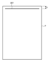
本実施形態では、工場出荷時に、例えば、所定の記録モードに設定して、図9に示すようなテストパターン901を記録用紙Pに記録させ、記録されたテストパターン901から記録用紙Pの先端位置と記録開始位置との距離Dを測定し、この値を理想距離(設計値)と比較し、その差を補正値としてLPもしくはPTOPの定数部分に反映させる。すなわち、理想値よりDが長い(補正値が+)場合は減算し、理想値よりDが短い(補正値が−)場合には加算することにより、記録装置個々のバラツキを補正することが可能である。
In the present embodiment, at the time of shipment from the factory, for example, a predetermined recording mode is set, a
測定されたDの値又は理想値との差(補正値)は、本体内の不揮発性の記憶手段(EPROM等)に格納するのが好ましい。上述したように、本実施形態の頭出し動作は、速度に依存しないため、この補正値は駆動速度によって変化させる必要が無く、ある速度で取得された補正値を全ての条件で適応可能である。 The difference (correction value) from the measured D value or ideal value is preferably stored in a non-volatile storage means (such as EPROM) in the main body. As described above, since the cueing operation of the present embodiment does not depend on the speed, the correction value does not need to be changed depending on the driving speed, and the correction value acquired at a certain speed can be applied under all conditions. .
また、図9のテストパターンの変わりに図10のようなテストパターンを記録させ、記録先端で切り取られた部分を目視で判断し、補正値を入力するようにしてもよい。図10のテストパターン101は、一定の傾きの直線と該直線から所定間隔で図中下方に引き出された複数の直線からなり、下方に引き出された各直線には−4から4までの数値がそれぞれ対応して記録されている。
In addition, a test pattern as shown in FIG. 10 may be recorded instead of the test pattern shown in FIG. 9, and a portion cut off at the leading end of the recording may be visually determined to input a correction value. The
図示した例では、実線部が記録用紙P上に記録され、破線部は記録用紙Pの外部にはみ出して記録されなかったパターンである。ここで、記録用紙Pの先端と傾斜した直線との境に位置する数値(この図では−1)を補正値として設定し、基準となる数値(例えば、図中0)との差をLP値もしくはPTOPの定数部分に反映させるよう、本体内の不揮発性の記憶手段(EPROM等)に格納することで、上記と同様の効果が得られる。 In the illustrated example, the solid line portion is recorded on the recording paper P, and the broken line portion is a pattern that protrudes outside the recording paper P and is not recorded. Here, a numerical value (-1 in this figure) located at the boundary between the leading edge of the recording paper P and the inclined straight line is set as a correction value, and the difference from the reference numerical value (for example, 0 in the figure) is the LP value. Alternatively, the same effect as described above can be obtained by storing in a non-volatile storage means (such as EPROM) in the main body so as to be reflected in the constant part of PTOP.
なお、テストパターンは、図9や図10に示したパターンに限定するものではなく、記録用紙の頭出し量を直接もしくは間接的に測定できる物であればよい。さらには、テストパターンを記録せずに、部品の公差や取り付け誤差に関する値を直接もしくは間接的に測定可能な手段を設けて、得られた値に基づいて定数部分を更新するようにしてもよい。 Note that the test pattern is not limited to the patterns shown in FIGS. 9 and 10, and may be any pattern that can directly or indirectly measure the cueing amount of the recording paper. Furthermore, it is possible to provide means capable of directly or indirectly measuring values related to component tolerances and mounting errors without recording a test pattern, and updating the constant portion based on the obtained values. .
このようなテストパターンの記録とそれに基づいた補正が行なわれるタイミングは、工場の出荷時に限定するものではなく、ユーザやサービスマンが必要に応じて適宜行ってもよい。補正値を入力する方法(インターフェース)としては、工場やサービスマンが使用する治具を用いても良いし、プリンタドライバ、記憶装置のキー操作等でも構わない。各記録装置で実際に記録等を行い、その結果に基づいて補正することにより、個々の記録装置の部品や取り付けに起因する誤差をキャンセルするものであれば、本実施形態の範疇に含まれるものと理解されよう。 The timing at which such test pattern recording and correction based on the test pattern are performed is not limited at the time of factory shipment, and may be appropriately performed by a user or a service person as needed. As a method (interface) for inputting the correction value, a jig used by a factory or a service person may be used, or a key operation of a printer driver or a storage device may be used. Any recording apparatus that actually records, etc., and corrects based on the result to cancel errors due to individual recording apparatus parts and attachments are included in the scope of this embodiment. It will be understood.
<他の実施形態>
以上の説明ではシリアル式のインクジェット記録装置に本発明を適用した例を挙げて説明したが、本発明はこれに限定されることなく、給紙動作と搬送動作とを異なるモータで制御する構成であれば、例えば、フルライン式の記録装置にも適用できる。
<Other embodiments>
In the above description, an example in which the present invention is applied to a serial type ink jet recording apparatus has been described. However, the present invention is not limited to this, and a configuration in which a sheet feeding operation and a conveying operation are controlled by different motors. For example, it can be applied to a full-line type recording apparatus.
なお、本発明は、複数の機器(例えばホストコンピュータ,インターフェース機器,リーダ,プリンタなど)から構成されるシステムに適用しても、一つの機器からなる装置(例えば、複写機,ファクシミリ装置など)に適用してもよい。 Note that the present invention can be applied to a system (for example, a copier, a facsimile machine, etc.) consisting of a single device even when applied to a system composed of a plurality of devices (for example, a host computer, interface device, reader, printer, etc.). You may apply.
また、本発明の目的は、前述した実施形態の機能を実現するソフトウェアのプログラムコードを記録した記憶媒体を、システムあるいは装置に供給し、そのシステムあるいは装置のコンピュータ(またはCPUやMPU)が記憶媒体に格納されたプログラムコードを読出し実行することによっても、達成されることは言うまでもない。 Another object of the present invention is to supply a storage medium storing software program codes for implementing the functions of the above-described embodiments to a system or apparatus, and the computer (or CPU or MPU) of the system or apparatus stores the storage medium. Needless to say, this can also be achieved by reading and executing the program code stored in the.
この場合、記憶媒体から読出されたプログラムコード自体が前述した実施形態の機能を実現することになり、そのプログラムコードを記憶した記憶媒体は本発明を構成することになる。 In this case, the program code itself read from the storage medium realizes the functions of the above-described embodiments, and the storage medium storing the program code constitutes the present invention.
プログラムコードを供給するための記憶媒体としては、例えば、フロッピディスク,ハードディスク,光ディスク,光磁気ディスク,CD−ROM,CD−R,磁気テープ,不揮発性のメモリカード,ROMなどを用いることができる。 As a storage medium for supplying the program code, for example, a floppy disk, a hard disk, an optical disk, a magneto-optical disk, a CD-ROM, a CD-R, a magnetic tape, a nonvolatile memory card, a ROM, or the like can be used.
また、コンピュータが読出したプログラムコードを実行することにより、前述した実施形態の機能が実現されるだけでなく、そのプログラムコードの指示に基づき、コンピュータ上で稼働しているOS(オペレーティングシステム)などが実際の処理の一部または全部を行い、その処理によって前述した実施形態の機能が実現される場合も含まれることは言うまでもない。 Further, by executing the program code read by the computer, not only the functions of the above-described embodiments are realized, but also an OS (operating system) operating on the computer based on the instruction of the program code. It goes without saying that a case where the function of the above-described embodiment is realized by performing part or all of the actual processing and the processing is included.
さらに、記憶媒体から読出されたプログラムコードが、コンピュータに挿入された機能拡張ボードやコンピュータに接続された機能拡張ユニットに備わるメモリに書込まれた後、そのプログラムコードの指示に基づき、その機能拡張ボードや機能拡張ユニットに備わるCPUなどが実際の処理の一部または全部を行い、その処理によって前述した実施形態の機能が実現される場合も含まれることは言うまでもない。 Further, after the program code read from the storage medium is written into a memory provided in a function expansion board inserted into the computer or a function expansion unit connected to the computer, the function expansion is performed based on the instruction of the program code. It goes without saying that the CPU or the like provided in the board or the function expansion unit performs part or all of the actual processing, and the functions of the above-described embodiments are realized by the processing.
本発明を上記記憶媒体に適用する場合、その記憶媒体には、先に説明した(図7に示す)フローチャートに対応するプログラムコードが格納されることになる。 When the present invention is applied to the storage medium, the storage medium stores program codes corresponding to the flowchart described above (shown in FIG. 7).
1 圧板
2 給紙ベース
3 サイドガイド
4 搬送ローラ
5 ピンチローラ
6 ピンチローラガイド
7 記録ヘッドカートリッジ
8 プラテン
9 キャリッジ
10 ガイド軸
11 ガイドレール
12 シャーシ
13 キャリッジモータ
14 タイミングベルト
15 アイドルプーリ
16 電気基板
17 フレキシブルケーブル
18 リニアスケール
19 排紙ローラ
20 排紙ローラギア
21 キャップ
22 ワイパー
23 PGモータ
24 ポンプ
25 搬送モータ
26 搬送エンコーダスケール
27 搬送ローラギア
28 搬送エンコーダセンサ
29 搬送エンコーダセンホルダ
30 搬送タイミングベルト
31 排紙伝達ギア
32 給紙モータ
33 給紙ローラ
34 給紙エンコーダスケール
35 給紙エンコーダセンサ
36 記録用紙端部検知センサ
37 ペーパーガイド
38 記録用紙端部検知センサレバー
39 記録用紙スタック
P 記録用紙
DESCRIPTION OF SYMBOLS 1
Claims (7)
給紙ローラ、及び前記給紙ローラを駆動し、前記給紙ローラの回転量に基づいてサーボ制御される給紙モータを有し、前記積載手段に積載された記録媒体を1枚ずつピックアップして前記給紙ローラによって給紙する給紙手段と、
搬送ローラ、該搬送ローラに対向して設けられたピンチローラ、及び前記搬送ローラを駆動し、前記搬送ローラの回転量に基づいてサーボ制御される搬送モータを有し、前記給紙手段によって給紙された記録媒体を前記搬送ローラと前記ピンチローラとで狭持して記録領域に搬送する搬送手段と、
前記積載手段から前記搬送手段までの搬送経路に設けられ、記録媒体の先端の通過を検出する先端検出手段と、
前記先端検出手段によって記録媒体の先端が検出される位置から所定位置までの記録媒体の第1の搬送距離を、前記給紙ローラの回転量に基づいて制御し、前記所定位置から前記記録領域の記録開始位置までの記録媒体の第2の搬送距離を、前記搬送ローラの回転量に基づいて制御することで、前記先端検出手段によって記録媒体の先端が検出される位置から前記記録開始位置までの記録媒体の搬送を連続して行う制御手段と
を備え、
前記所定位置は、
前記先端検出手段によって記録媒体の先端が検出される位置と前記記録領域との間の搬送経路に定められ、記録媒体が前記搬送ローラと前記ピンチローラとによって狭持されるニップ位置もしくは前記ニップ位置の前記記録領域側に定められていることを特徴とする記録装置。 A loading means for loading a plurality of recording media;
A paper feed roller, and a paper feed motor that drives the paper feed roller and is servo-controlled based on the rotation amount of the paper feed roller, and picks up the recording media stacked on the stacking means one by one A paper feed means for feeding paper by the paper feed roller;
A conveyance roller, a pinch roller provided opposite to the conveyance roller, and a conveyance motor that drives the conveyance roller and is servo-controlled based on a rotation amount of the conveyance roller , and feeds paper by the paper feeding unit Conveying means for nipping the recorded recording medium between the conveying roller and the pinch roller and conveying the recording medium to a recording area;
A leading edge detecting means provided in a conveying path from the stacking means to the conveying means, for detecting passage of the leading edge of the recording medium;
A first conveying distance of the recording medium from the position where the tip is discovered in the recording medium by said front edge detecting means to a predetermined position, and the control based on the rotation amount of the feed roller, from the predetermined position of the recording area By controlling the second conveyance distance of the recording medium to the recording start position based on the rotation amount of the conveyance roller, the position from the position where the leading end of the recording medium is detected by the leading end detection unit to the recording start position is determined. and a control means for conveying the recording medium in succession,
The predetermined position is
A nip position or a nip position that is defined in a conveyance path between a position where the leading edge of the recording medium is detected by the leading edge detection means and the recording area, and the recording medium is nipped by the conveyance roller and the pinch roller A recording apparatus characterized in that the recording apparatus is defined on the recording area side .
前記先端検出手段による記録媒体の先端の検出をトリガにして前記給紙ローラの回転量のカウントを開始し、前記給紙ローラの回転量のカウントが前記第1の搬送距離に対応する値になることをトリガにして前記搬送ローラの回転量のカウントを開始することを特徴とする請求項1に記載の記録装置。 The control means includes
Counting the rotation amount of the paper feed roller is triggered by the detection of the front edge of the recording medium by the front edge detection means, and the rotation amount count of the paper feed roller becomes a value corresponding to the first transport distance. The recording apparatus according to claim 1, wherein counting of the rotation amount of the transport roller is started using this as a trigger .
前記先端検出手段によって記録媒体の先端が検出される位置から所定位置までの記録媒体の第1の搬送距離を、前記給紙ローラの回転量に基づいて制御する第1搬送距離制御工程と、
前記所定位置から前記記録領域の記録開始位置までの記録媒体の第2の搬送距離を、前記搬送ローラの回転量に基づいて制御することで、前記先端検出手段によって記録媒体の先端が検出される位置から前記記録開始位置までの記録媒体の搬送を連続して行う第2搬送距離制御工程とを有し、
前記所定位置は、
前記先端検出手段によって記録媒体の先端が検出される位置と前記記録領域との間の搬送経路に定められ、記録媒体が前記搬送ローラと前記ピンチローラとによって狭持されるニップ位置もしくは前記ニップ位置の前記記録領域側に定められている
ことを特徴とする記録装置の頭出し位置制御方法。 A stacking unit configured to stack a plurality of recording media; a sheet feeding roller; and a sheet feeding motor that drives the sheet feeding roller and is servo-controlled based on a rotation amount of the sheet feeding roller. a sheet feeding means for feeding paper by said paper feed roller a stacked recording medium are picked up one by one, conveying roller, a pinch roller disposed opposite to the conveying roller, and drives the conveyor rollers, wherein A conveyance motor that is servo-controlled based on the rotation amount of the sheet feeding roller, and conveys the recording medium fed by the sheet feeding unit to the recording area by being sandwiched between the conveyance roller and the pinch roller. A cueing position control method for a recording apparatus, comprising: and a front end detecting unit provided in a transport path from the stacking unit to the transport unit and detecting the passage of the front end of the recording medium,
A first conveying distance control step of controlling based on the first conveyance distance of the recording medium from the position where the tip is discovered in the recording medium to a predetermined position, the rotation amount of the paper feed roller by said front edge detecting means,
By controlling the second conveyance distance of the recording medium from the predetermined position to the recording start position of the recording area based on the rotation amount of the conveyance roller, the leading edge of the recording medium is detected by the leading edge detection unit. second possess a conveying distance control step of performing the position continuously conveying the recording medium to the recording start position,
The predetermined position is
A nip position or a nip position that is defined in a conveyance path between a position where the leading edge of the recording medium is detected by the leading edge detection means and the recording area, and the recording medium is nipped by the conveyance roller and the pinch roller A cueing position control method for a recording apparatus, wherein the cueing position control method is defined on the recording area side .
Priority Applications (1)
| Application Number | Priority Date | Filing Date | Title |
|---|---|---|---|
| JP2004159832A JP4484586B2 (en) | 2004-05-28 | 2004-05-28 | Recording apparatus and cueing position control method of recording apparatus |
Applications Claiming Priority (1)
| Application Number | Priority Date | Filing Date | Title |
|---|---|---|---|
| JP2004159832A JP4484586B2 (en) | 2004-05-28 | 2004-05-28 | Recording apparatus and cueing position control method of recording apparatus |
Publications (3)
| Publication Number | Publication Date |
|---|---|
| JP2005335302A JP2005335302A (en) | 2005-12-08 |
| JP2005335302A5 JP2005335302A5 (en) | 2007-07-12 |
| JP4484586B2 true JP4484586B2 (en) | 2010-06-16 |
Family
ID=35489377
Family Applications (1)
| Application Number | Title | Priority Date | Filing Date |
|---|---|---|---|
| JP2004159832A Active JP4484586B2 (en) | 2004-05-28 | 2004-05-28 | Recording apparatus and cueing position control method of recording apparatus |
Country Status (1)
| Country | Link |
|---|---|
| JP (1) | JP4484586B2 (en) |
Families Citing this family (6)
| Publication number | Priority date | Publication date | Assignee | Title |
|---|---|---|---|---|
| JP4497481B2 (en) * | 2006-07-06 | 2010-07-07 | キヤノン株式会社 | Recording apparatus, paper feeding apparatus, and paper feeding control method |
| US7686301B2 (en) | 2006-07-06 | 2010-03-30 | Canon Kabushiki Kaisha | Printing apparatus, feeding apparatus, and feeding control method |
| JP4586889B2 (en) * | 2008-06-06 | 2010-11-24 | セイコーエプソン株式会社 | Conveying apparatus, recording apparatus, and conveying method |
| JP5488455B2 (en) | 2010-12-28 | 2014-05-14 | ブラザー工業株式会社 | Transport device |
| JP6065801B2 (en) * | 2013-09-30 | 2017-01-25 | ブラザー工業株式会社 | Sheet conveying apparatus and image forming system |
| JP7453870B2 (en) | 2020-07-17 | 2024-03-21 | 株式会社Pfu | Media transport device, control method and control program |
Citations (5)
| Publication number | Priority date | Publication date | Assignee | Title |
|---|---|---|---|---|
| JP2003103875A (en) * | 2001-10-01 | 2003-04-09 | Canon Inc | Printer, its drive control method, print system comprising it, and program for executing the method |
| JP2003114555A (en) * | 2001-10-04 | 2003-04-18 | Toshiba Mach Co Ltd | Printing machine and printing method |
| JP2003291433A (en) * | 2002-03-29 | 2003-10-14 | Brother Ind Ltd | Sheet feeder |
| JP2004114618A (en) * | 2002-09-27 | 2004-04-15 | Seiko Epson Corp | Feed device, printer, feed method, program and computer system |
| JP2004136453A (en) * | 2002-10-15 | 2004-05-13 | Seiko Epson Corp | Recorder, recording method, program and computer system |
-
2004
- 2004-05-28 JP JP2004159832A patent/JP4484586B2/en active Active
Patent Citations (5)
| Publication number | Priority date | Publication date | Assignee | Title |
|---|---|---|---|---|
| JP2003103875A (en) * | 2001-10-01 | 2003-04-09 | Canon Inc | Printer, its drive control method, print system comprising it, and program for executing the method |
| JP2003114555A (en) * | 2001-10-04 | 2003-04-18 | Toshiba Mach Co Ltd | Printing machine and printing method |
| JP2003291433A (en) * | 2002-03-29 | 2003-10-14 | Brother Ind Ltd | Sheet feeder |
| JP2004114618A (en) * | 2002-09-27 | 2004-04-15 | Seiko Epson Corp | Feed device, printer, feed method, program and computer system |
| JP2004136453A (en) * | 2002-10-15 | 2004-05-13 | Seiko Epson Corp | Recorder, recording method, program and computer system |
Also Published As
| Publication number | Publication date |
|---|---|
| JP2005335302A (en) | 2005-12-08 |
Similar Documents
| Publication | Publication Date | Title |
|---|---|---|
| US7415239B2 (en) | Conveying apparatus and recording apparatus having the same | |
| JP5354975B2 (en) | Recording apparatus and conveyance control method | |
| US7176649B2 (en) | DC motor control apparatus and recording apparatus | |
| JP4366150B2 (en) | Recording device | |
| US7918526B2 (en) | Printer and method preventing false detection of a detected object | |
| JP4484586B2 (en) | Recording apparatus and cueing position control method of recording apparatus | |
| JP5610834B2 (en) | Image recording device | |
| JP2006036490A (en) | Conveying device, recording device and conveying control method for recording device | |
| JP2022048548A (en) | Recording device, and control method for recording device | |
| JP5993842B2 (en) | Recording apparatus and control method | |
| JP4362815B2 (en) | Platen gap adjusting device, printing device, and motor control device | |
| JP4781455B2 (en) | Recording device | |
| JP2010042562A (en) | Recording apparatus, and control method of recording apparatus | |
| JP2001341368A (en) | Method for detecting trailing end of recording medium and recorder | |
| JP2002310613A (en) | Measurement system, printer sheet carrying control method for printer, and linear encoder used for the carrying control | |
| JP7334400B2 (en) | recording device | |
| JP2013028004A (en) | Recorder and method for controlling conveyance of recording medium | |
| US20240007577A1 (en) | Image Recording Device, Method of Controlling Image Recording Device, and Non-Transitory Computer-Readable Recording Medium Therefor | |
| JP4823333B2 (en) | Recording device | |
| JP2002144546A (en) | Ink jet recorder and its controlling method | |
| JP6357810B2 (en) | Image forming apparatus | |
| JP5295210B2 (en) | Conveying device and recording apparatus provided with the device | |
| JP5550761B2 (en) | Recording apparatus and recording apparatus control method | |
| JP5927831B2 (en) | Motor control device | |
| JP2023017511A (en) | Transport device and image recording device |
Legal Events
| Date | Code | Title | Description |
|---|---|---|---|
| A521 | Written amendment |
Free format text: JAPANESE INTERMEDIATE CODE: A523 Effective date: 20070528 |
|
| A621 | Written request for application examination |
Free format text: JAPANESE INTERMEDIATE CODE: A621 Effective date: 20070528 |
|
| RD03 | Notification of appointment of power of attorney |
Free format text: JAPANESE INTERMEDIATE CODE: A7423 Effective date: 20070528 |
|
| A977 | Report on retrieval |
Free format text: JAPANESE INTERMEDIATE CODE: A971007 Effective date: 20090527 |
|
| A131 | Notification of reasons for refusal |
Free format text: JAPANESE INTERMEDIATE CODE: A131 Effective date: 20090619 |
|
| A521 | Written amendment |
Free format text: JAPANESE INTERMEDIATE CODE: A523 Effective date: 20090818 |
|
| TRDD | Decision of grant or rejection written | ||
| A01 | Written decision to grant a patent or to grant a registration (utility model) |
Free format text: JAPANESE INTERMEDIATE CODE: A01 Effective date: 20100319 |
|
| A01 | Written decision to grant a patent or to grant a registration (utility model) |
Free format text: JAPANESE INTERMEDIATE CODE: A01 |
|
| A61 | First payment of annual fees (during grant procedure) |
Free format text: JAPANESE INTERMEDIATE CODE: A61 Effective date: 20100323 |
|
| R150 | Certificate of patent or registration of utility model |
Ref document number: 4484586 Country of ref document: JP Free format text: JAPANESE INTERMEDIATE CODE: R150 Free format text: JAPANESE INTERMEDIATE CODE: R150 |
|
| FPAY | Renewal fee payment (event date is renewal date of database) |
Free format text: PAYMENT UNTIL: 20130402 Year of fee payment: 3 |
|
| FPAY | Renewal fee payment (event date is renewal date of database) |
Free format text: PAYMENT UNTIL: 20130402 Year of fee payment: 3 |
|
| FPAY | Renewal fee payment (event date is renewal date of database) |
Free format text: PAYMENT UNTIL: 20140402 Year of fee payment: 4 |