EP0133786B1 - Piston rings - Google Patents
Piston rings Download PDFInfo
- Publication number
- EP0133786B1 EP0133786B1 EP84305146A EP84305146A EP0133786B1 EP 0133786 B1 EP0133786 B1 EP 0133786B1 EP 84305146 A EP84305146 A EP 84305146A EP 84305146 A EP84305146 A EP 84305146A EP 0133786 B1 EP0133786 B1 EP 0133786B1
- Authority
- EP
- European Patent Office
- Prior art keywords
- ring
- piston
- rings
- piston ring
- engine
- Prior art date
- Legal status (The legal status is an assumption and is not a legal conclusion. Google has not performed a legal analysis and makes no representation as to the accuracy of the status listed.)
- Expired
Links
Images

Classifications
-
- F—MECHANICAL ENGINEERING; LIGHTING; HEATING; WEAPONS; BLASTING
- F16—ENGINEERING ELEMENTS AND UNITS; GENERAL MEASURES FOR PRODUCING AND MAINTAINING EFFECTIVE FUNCTIONING OF MACHINES OR INSTALLATIONS; THERMAL INSULATION IN GENERAL
- F16J—PISTONS; CYLINDERS; SEALINGS
- F16J9/00—Piston-rings, e.g. non-metallic piston-rings, seats therefor; Ring sealings of similar construction
- F16J9/26—Piston-rings, e.g. non-metallic piston-rings, seats therefor; Ring sealings of similar construction characterised by the use of particular materials
-
- F—MECHANICAL ENGINEERING; LIGHTING; HEATING; WEAPONS; BLASTING
- F16—ENGINEERING ELEMENTS AND UNITS; GENERAL MEASURES FOR PRODUCING AND MAINTAINING EFFECTIVE FUNCTIONING OF MACHINES OR INSTALLATIONS; THERMAL INSULATION IN GENERAL
- F16J—PISTONS; CYLINDERS; SEALINGS
- F16J9/00—Piston-rings, e.g. non-metallic piston-rings, seats therefor; Ring sealings of similar construction
- F16J9/28—Piston-rings, e.g. non-metallic piston-rings, seats therefor; Ring sealings of similar construction of non-metals
-
- F—MECHANICAL ENGINEERING; LIGHTING; HEATING; WEAPONS; BLASTING
- F02—COMBUSTION ENGINES; HOT-GAS OR COMBUSTION-PRODUCT ENGINE PLANTS
- F02B—INTERNAL-COMBUSTION PISTON ENGINES; COMBUSTION ENGINES IN GENERAL
- F02B1/00—Engines characterised by fuel-air mixture compression
- F02B1/02—Engines characterised by fuel-air mixture compression with positive ignition
- F02B1/04—Engines characterised by fuel-air mixture compression with positive ignition with fuel-air mixture admission into cylinder
-
- Y—GENERAL TAGGING OF NEW TECHNOLOGICAL DEVELOPMENTS; GENERAL TAGGING OF CROSS-SECTIONAL TECHNOLOGIES SPANNING OVER SEVERAL SECTIONS OF THE IPC; TECHNICAL SUBJECTS COVERED BY FORMER USPC CROSS-REFERENCE ART COLLECTIONS [XRACs] AND DIGESTS
- Y10—TECHNICAL SUBJECTS COVERED BY FORMER USPC
- Y10S—TECHNICAL SUBJECTS COVERED BY FORMER USPC CROSS-REFERENCE ART COLLECTIONS [XRACs] AND DIGESTS
- Y10S277/00—Seal for a joint or juncture
- Y10S277/935—Seal made of a particular material
- Y10S277/936—Composite
-
- Y—GENERAL TAGGING OF NEW TECHNOLOGICAL DEVELOPMENTS; GENERAL TAGGING OF CROSS-SECTIONAL TECHNOLOGIES SPANNING OVER SEVERAL SECTIONS OF THE IPC; TECHNICAL SUBJECTS COVERED BY FORMER USPC CROSS-REFERENCE ART COLLECTIONS [XRACs] AND DIGESTS
- Y10—TECHNICAL SUBJECTS COVERED BY FORMER USPC
- Y10S—TECHNICAL SUBJECTS COVERED BY FORMER USPC CROSS-REFERENCE ART COLLECTIONS [XRACs] AND DIGESTS
- Y10S277/00—Seal for a joint or juncture
- Y10S277/935—Seal made of a particular material
- Y10S277/944—Elastomer or plastic
- Y10S277/945—Containing fluorine
- Y10S277/946—PTFE
Definitions
- the invention relates to piston rings for internal combustion engines of all kinds, and for pumps or compressors and in particular to piston rings which can be used as compression rings or as oil control rings or as both compression and oil control rings simultaneously.
- the invention also includes within its scope internal combustion engines containing such piston rings and methods of making such piston rings.
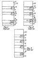
- the petrol engine piston 10 is formed with three annular piston ring grooves 11,12,13 containing corresponding piston rings 14,15,16. All the piston rings are made of a metalliferous material such as cast iron or steel.
- the uppermost piston ring 14 that is the piston ring closest to the crown 17 of the piston, is a compression ring of rectangular cross-section.
- This compression ring 14 is of such an initial diameter that when the piston is inserted into a corresponding cylinder or liner (not shown) the ring presses outwardly against the cylinder or liner to seal the compression ring against the corresponding cylinder or liner to prevent the high pressure gas from the combustion chamber leaking down the sides of the piston (so- called "blow-by").
- the middle ring 15 is also a compression ring and is trapezoidal in cross-section with a lower projecting edge 18 for providing a second gas seal against the associated cylinder or liner.
- the lowermost piston ring 16 is an oil control ring which is formed by two flat annular rails 19, 20 which are urged outwardly against the associated cylinder or liner and which are separated by a spring expander 21.
- the purpose of the oil control ring is to control the supply of lubricant to the compression rings by rejecting oil downwardly, leaving only a thin film on the cylinder wall.
- the diesel engine piston 30 is provided with three piston ring grooves 31, 32, 33 containing respective piston rings 34, 35, 36. All the piston rings are made of metalliferous material such as steel or cast iron.
- the two upper rings 34, 35 are compression rings; the uppermost being of generally trapezoidal shape but having a curved surface 37 for contacting the associated cylinder liner.
- the lowermost ring 36 is an oil control ring formed as an annular member having two circumferential projecting edges 38, 39 formed by cutting away the metal of the rings.
- a plurality of angularly spaced radially extending holes or slots 40 are provided in this ring to allow oil to drain away into the interior of the associated groove, from which it may be removed by holes or slots (not shown) leading into the interior of the piston.
- An expander 41 is provided for urging the oil control ring 36 outwardly against the associated cylinder or liner.
- the second diesel engine piston 50 has four piston ring grooves 51, 52, 53 and 54 containing respective rings 55, 56, 57 and 58.
- all the rings are made from a metalliferous material such as cast iron or steel.
- compression rings 55, 56 and 57 are provided.
- the uppermost ring is of similar construction to the uppermost ring 34 in the piston of Figure 2 while the two intermediate rings 56, 57 are each substantially the same as the intermediate ring 15 in the piston of Figure 1.
- the lower ring 58 is an oil control ring substantially the same as the oil control ring 36 of the piston of Figure 2.
- the forces must be high to improve conformability, for example, the outwardly directed pressure may be 2 MN/m 2 or above. This tends to increase the frictional forces between the piston ring and the associated cylinder.
- the purpose of the oil control ring is to meter a lubricant supply to the compression rings. It must therefore reject oil downwards leaving only a thin oil film on the cylinder. To achieve this film (probably less than 10 micrometers thick), an oil control ring should conform to the cylinder bore and dispose of rejected oil.
- favourable hydrodynamic action between the oil ring and the cylinder should be discouraged. This is normally achieved by using small areas of contact between the oil control rings and the cylinder and consequently high contact pressures. Some hydrodynamic action is, however, necessary with metallic rings, to reduce the severity of the ring/cylinder contact and so give a low enough wear rate for adequate service life.
- This gas pressure may provide a peak pressure to assist sealing in the range 7 MN/m 2 to 20 MN/m 2 ; in addition to the pressures of 0.10 MN/m 2 and above generated mechanically.
- an internal combustion engine of the kind including at least one cylinder or liner containing a piston which is for reciprocation therein and which has at least one piston ring groove carrying a piston ring, characterised in that the piston ring is made from a conformable non-metallic material, the piston ring having an expansion pressure against the associated cylinder or liner of between 0.10 and 1.50 MN/m 2 .
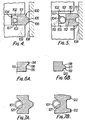
- the piston 100 is formed with a piston ring groove 101 having upper and lower radially extending surfaces 102, 103 connected by an axially and circumferentially extending base 104.
- the piston 100 is reciprocable within a cylinder or cylinder liner 104 of an internal combustion engine.
- the piston ring groove 101 contains a piston ring 105 formed of a conformable non-metallic material such as a tough crystalline thermoplastic material or an alloy thereof.
- a tough crystalline thermoplastic material is polyetheretherketon.
- This is a tough crystalline thermoplastic aromatic polyetherketone containing the repeating unit: and having an inherent viscosity of at least 0.7.
- the polyetheretherketone may be made by the polycondensation of hydroquinone and a 4-4'-dihalobenzophenone (a proportion of which is 4-4'- difluriobenzophenone) and an alkaline metal carbonate or bicarbonate, as described in European Patent Publication No. 0001879.
- the polyetheretherketone may be unreinforced or may be reinforced with carbon fibres, as disclosed in EP-A-0031198, which may be randomly arranged or may be oriented to extend, for example, around the piston ring.
- bronze, graphite or polytetrafluoroethylene may be added to the polyetheretherketone either together or separately.
- an alloy of the kind disclosed in British Patent Application No. 84.06547 may be used.
- the piston ring is produced by forming the polyetheretherketone or polyetheretherketone alloy, into a helical coil. This is preferably done by extrusion although it may be done by casting. Ths cross-section of the coil is the required cross-section of the finished piston ring. The coil is then slit along one side in a plane including its longitudinal axis to form a number of rings with a gap in them.
- piston rings may be produced separately by an injection moulding process.
- the ends of the piston ring may be separated by a small gap (generally less than 0.3 mm) to accommodate thermal expansion of the ring when hot.
- the ring ends may be allowed to butt together when hot, so improving gas sealing.
- the cross-sectional shape of the piston ring may be generally rectangular but with a trapezoidal projection 106 on the radially outer surface of the ring for co-operation with the associated cylinder or liner 108.
- the piston ring 105 is received in the piston ring groove 101 and is urged outwardly by a metallic expander element 107 arranged between the radially inner ends of the piston ring and the piston ring groove. It will be appreciated that, where the piston ring 105 is produced by injection moulding, the metallic expander element 107 may be located within the piston ring 105 by moulding the piston ring around the metallic expander element 107.
- the piston ring 105 may be urged outwardly against the corresponding cylinder or liner 108 by its own natural resilience. In either event, the outward force is such that the pressure between the piston ring 105 and the cylinder or liner 108 is between 0.10 and 1.50 MN/m 2 and is preferably of the order of 0.50 MN/m 2 .
- the piston ring groove 101 is provided with a lubricant drainage hole 109 which leads from beneath the piston ring 105 to the interior of the piston 100. This allows the piston ring 105 to act as both an oil control ring and a compression ring.
- the oil control ring 110 is of generally rectangular cross-section and is provided with upper and lower trapezoidal cross-section projections 111 whose narrower ends bear against the associated cylinder 108.
- In the channel between the two projections are a number of angularly spaced radially extending holes 112 which lead to the space between the radially inner ends of the piston ring and the piston ring groove.
- Further holes 113 lead from the radially inner end of the piston ring groove to the interior of the piston 100 and thence to the engine sump (not shown). Accordingly, oil scraped off the cylinder by the oil control ring 110 is passed through the holes to the sump.
- the oil control ring 110 urged outwardly by an expander 107 to achieve the same ring/cylinder pressures as the arrangement of Figure 4; that is to say a pressure of between 0.10 and 1.50 MNlm 2 and preferably 0.50 MN/ m 2 .
- Figures 6A and 6B show alternative cross-sectional shapes of the piston ring of either Figure 4 or Figure 5 to promote downward oil scraping action.
- the piston ring 113 is provided with an outward projection 114 at the upper edge thereof which is connected to the radially outer surface 115 of the piston ring by a curved portion 116.
- the projection 117 is formed by an upper downwardly and outwardly extending surface 118 and by a lower generally radially extending surface 119 is connected to the remainder of the piston ring at its inner end by a curved portion 120.
- piston ring may include upper and lower projections 122, each projection 122 being of trapezoidal cross-section narrowing as it extends away from the body of the piston ring.
- Figures 8, 9 and 10 show how the piston rings described above with reference to Figures 4 to 7 of the drawings can be incorporated in petrol and diesel engines. Parts common to these Figures and to Figures 4 and 7 will not be described in detail but will be given the same reference numerals.
- the Figure 8 embodiment shows an arrangement which can be substituted for the conventional arrangement of Figure 1. Referring both to Figure 8 and Figure 1, it will be seen that, in Figure 8, the intermediate compression ring 18 is omitted and that the arrangement of Figure 7A is substituted in its place, with the lower piston ring 105 acting as both a compression ring and an oil control ring.
- FIG 9 arrangement is an alternative to the conventional arrangement shown in Figure 2 and, referring to both these Figures, it will be seen, once again, that the intermediate ring 35 is omitted and the arrangement of Figures 4 and 7A substituted with the piston ring 105 acting as both a compression ring and an oil control ring.
- FIG 10 shows an arrangement which can be substituted for the conventional arrangement shown in Figure 3.
- one of the compression rings 57 is omitted and the arrangement of Figures 4 and 7A substituted.
- the piston ring 105 again acts as both a compression ring and an oil ring.
- the materials described above with reference to Figures 4 to 7 have a Youngs modulus which is a tenth or less that of metalliferous materials. Accordingly, they can achieve the same conformability or K value with one tenth or less of the wall pressure.
- piston rings of the kind described above with reference to Figures 4 to 10 have the advantage that they increase their conformability at a time when the distortion of the cylinder is at a maximum, i.e. when increased conformability is most required.
- a comparative test was performed using a single cylinder Petters AVB.D.I. diesel engine in which the piston initially had a piston ring arrangement of the kind shown in Figure 3 of the accompanying drawings and then had a piston ring arrangement of the kind shown in Figure 10. Two tests were performed, an initial proving test of 5 hours and a second test of 42 hours.
- the Figure 10 arrangement showed an observable decrease in fuel consumption and a slight decrease in oil consumption in comparison with the Figure 3 arrangement.
- the Figure 10 arrangement showed a reduction in ring radial width from 4mm to 3mm, radial ring wear of 20 micrometers (48 micrometers per 100 hours) and axial ring wear of 36 micrometers (85 micrometers per 100 hours).
- the engine was run at a relatively high rating for the final 20 hours of the test (at a 150 psi/10.3 ber bmep).
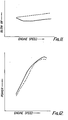
- a 4-cylinder 2.0 litre petrol engine was fitted first with a piston ring arrangement of the kind shown in Figure 1 and, second, with the lowermost piston ring of the Figure 1 arrangement replaced by a piston ring of the kind shown in Figure 4.
- measurements were made of the blow-by and the engine power at various engine speeds, after an initial 10 hours or running to "break-in" the engine and so obtain steady running. The results of these tests are shown in Figure 11 (blow-by) and Figure 12 (power), the conventional piston rings given the broken line and the Figure 4 ring the continuous line.
- the piston ring of Figure 4 provides a significant decrease in blow-by in comparison with a conventional piston ring arrangement.
- the improvement is particularly marked in the mid-range of engine speeds, which is the speed most common in engine operation in a vehicle.
- the engine power is correspondingly increased, as shown in Figure 12.
- the greatest improvement is in the commonly used mid-range of engine speeds. It is believed that the oil consumption of the engine including the piston ring of Figure 4 can be controlled to be not substantiate different from the oil consumption of the engine using the conventional piston ring arrangement of Figure 1.
Priority Applications (1)
| Application Number | Priority Date | Filing Date | Title |
|---|---|---|---|
| AT84305146T ATE44083T1 (de) | 1983-08-04 | 1984-07-30 | Kolbenring. |
Applications Claiming Priority (2)
| Application Number | Priority Date | Filing Date | Title |
|---|---|---|---|
| GB838321051A GB8321051D0 (en) | 1983-08-04 | 1983-08-04 | Piston rings |
| GB8321051 | 1983-08-04 |
Publications (3)
| Publication Number | Publication Date |
|---|---|
| EP0133786A2 EP0133786A2 (en) | 1985-03-06 |
| EP0133786A3 EP0133786A3 (en) | 1986-02-26 |
| EP0133786B1 true EP0133786B1 (en) | 1989-06-14 |
Family
ID=10546810
Family Applications (1)
| Application Number | Title | Priority Date | Filing Date |
|---|---|---|---|
| EP84305146A Expired EP0133786B1 (en) | 1983-08-04 | 1984-07-30 | Piston rings |
Country Status (9)
| Country | Link |
|---|---|
| US (1) | US4629200A (ko) |
| EP (1) | EP0133786B1 (ko) |
| KR (1) | KR890004052B1 (ko) |
| AT (1) | ATE44083T1 (ko) |
| AU (1) | AU562386B2 (ko) |
| CA (1) | CA1254919A (ko) |
| DE (1) | DE3478711D1 (ko) |
| GB (2) | GB8321051D0 (ko) |
| IN (1) | IN162138B (ko) |
Cited By (1)
| Publication number | Priority date | Publication date | Assignee | Title |
|---|---|---|---|---|
| DE10030368A1 (de) * | 2000-06-21 | 2002-01-03 | Daimler Chrysler Ag | Verfahren zum Ermitteln des Formfüllvermögens von Kolbenringen |
Families Citing this family (43)
| Publication number | Priority date | Publication date | Assignee | Title |
|---|---|---|---|---|
| FR2594489B1 (fr) * | 1986-02-14 | 1989-10-20 | Geffroy Robert | Segment racleur perfectionne et ensemble a pistons coulissant dans des cylindres, tel que moteur a combustion interne, comportant de tels segments |
| US4811621A (en) * | 1986-06-19 | 1989-03-14 | Teleflex Incorporated | Remote control assembly transmission seal |
| US4753444A (en) * | 1986-10-30 | 1988-06-28 | Otis Engineering Corporation | Seal and seal assembly for well tools |
| JPH02118177U (ko) * | 1989-03-09 | 1990-09-21 | ||
| BR9204209A (pt) * | 1991-11-25 | 1993-06-01 | Dana Corp | Conjunto de anel de pistao |
| US5267838A (en) * | 1992-01-03 | 1993-12-07 | Baugh Benton F | Severe service compressor system |
| DE4210804A1 (de) * | 1992-04-01 | 1993-10-07 | Mtu Muenchen Gmbh | Einrichtung zur Abdichtung eines Spaltes zwischen winkelversetzt und fest oder relativ zueinander beweglich angeordneten Wandelementen |
| DE4237886A1 (de) * | 1992-09-11 | 1994-03-17 | Mtu Muenchen Gmbh | Einrichtung zur Abdichtung fluidisch unterschiedlich druckbeaufschlagter Räume zwischen relativ zueinander beweglichen Gehäusen, insbesondere von Flugtriebwerken |
| KR960023949A (ko) * | 1994-12-28 | 1996-07-20 | 수우 에이 그리핀 | 가요성 유체 시일 |
| JPH08200182A (ja) * | 1995-01-25 | 1996-08-06 | Zexel Corp | 電磁式燃料噴射弁およびその取付け構造 |
| US5564699A (en) * | 1995-02-15 | 1996-10-15 | Caterpillar Inc. | Side and gap sealed oil ring |
| DE19605457A1 (de) * | 1995-02-15 | 1996-08-22 | Caterpillar Inc | Seiten- und spaltengedichteter Ölring |
| US6044819A (en) * | 1996-03-06 | 2000-04-04 | The United States Of America As Represented By The Administrator Of The National Aeronautics And Space Administration | Pistons and cylinders made of carbon-carbon composite materials |
| US5711206A (en) * | 1996-06-06 | 1998-01-27 | Westinghouse Air Brake Company | Piston and cylinder assembly for minimizing water blow-by in an air compressor |
| US5779243A (en) * | 1996-11-21 | 1998-07-14 | Delaware Capital Formation, Inc. | Piston ring set for reciprocating engines |
| DE59711347D1 (de) | 1997-06-02 | 2004-04-01 | Burckhardt Compression Ag Wint | Dichtelement für trockenlaufsysteme und verwendung eines solchen dichtelements |
| US6289872B1 (en) * | 1999-02-04 | 2001-09-18 | Dimitrios Dardalis | Rotating sleeve engine |
| JP2002039062A (ja) * | 2000-07-26 | 2002-02-06 | Toyota Industries Corp | 圧縮機 |
| BR0202271B1 (pt) * | 2001-05-30 | 2011-04-05 | anel de óleo para motor de combustão interna. | |
| KR100447455B1 (ko) * | 2001-07-30 | 2004-09-07 | 삼영기계주식회사 | 2사이클 기관용 피스톤 |
| JP2003113940A (ja) * | 2001-08-02 | 2003-04-18 | Riken Corp | スチール製ピストンリング |
| US6685193B2 (en) * | 2001-08-30 | 2004-02-03 | Illinois Tool Works Inc. | Self lubricating, non-sealing piston ring for an internal combustion fastener driving tool |
| US6837205B1 (en) * | 2002-10-28 | 2005-01-04 | Richard F. Chipperfield | Internal combustion engine |
| KR100674425B1 (ko) * | 2004-11-17 | 2007-01-31 | 삼영기계(주) | 오일 스크래퍼링이 설치된 피스톤 장치 |
| US7140291B2 (en) * | 2005-01-28 | 2006-11-28 | Bendix Commercial Vehicle Systems Llc | Oil-free/oil-less air compressor with an improved seal |
| US7819958B2 (en) * | 2005-08-08 | 2010-10-26 | Bendix Commerical Vehicle Systems Llc | Purge valve |
| EP1793144A1 (fr) * | 2005-12-05 | 2007-06-06 | Jean Frédéric Melchior | Dispositif d'étanchéité pour piston pour monteur alternatif à combustion interne ou compresseur alternatif, et ensemble comprenant un tel piston |
| DE102006045993A1 (de) * | 2006-09-27 | 2008-04-24 | Andritz Küsters GmbH & Co. KG | Durchbiegungssteuerbare Walze |
| US20110290812A1 (en) * | 2008-10-20 | 2011-12-01 | Garver Theodore M | Interactive sealing arrangement pressurized fluid storage system and method |
| CA2667320A1 (en) * | 2009-06-08 | 2010-12-08 | Noetic Technologies Inc. | Seal assembly |
| US20100314838A1 (en) * | 2009-06-15 | 2010-12-16 | Noetic Technologies Inc. | Seal assembly |
| DE102010001434B4 (de) * | 2010-02-01 | 2016-02-25 | Federal-Mogul Burscheid Gmbh | Ölabstreif-Kolbenring |
| US8573113B2 (en) | 2010-04-30 | 2013-11-05 | Bendix Commercial Vehicle Systems Llc | Piston and cylinder assembly |
| US20120085313A1 (en) * | 2010-10-12 | 2012-04-12 | Reisser Heinz-Gustav A | Piston-head design for use in an internal combustion engine |
| DE102012006834A1 (de) | 2011-09-13 | 2013-03-14 | Wabco Gmbh | Hubkolben für einen Hubkolbenkompressor zur Erzeugung von Druckluft für ein Fahrzeug |
| IN2014DN07964A (ko) * | 2012-03-01 | 2015-05-01 | Torad Engineering Llc | |
| US10077838B2 (en) * | 2015-07-10 | 2018-09-18 | Ford Global Technologies, Llc | Piston ring configured to reduce friction |
| DE102015111672A1 (de) * | 2015-07-17 | 2017-01-19 | Federal-Mogul Burscheid Gmbh | Kolbenring |
| US10125719B2 (en) * | 2015-10-30 | 2018-11-13 | Tenneco Inc. | Piston, oil control ring therefor and method of construction thereof |
| KR101688953B1 (ko) * | 2016-06-10 | 2016-12-22 | 고성완 | 무산소 과열 건조식 음식물 쓰레기 처리장치 |
| CA3056503A1 (en) | 2019-09-24 | 2021-03-24 | Coutts Industries Inc. | Internal combustion engine |
| DE102021105203A1 (de) | 2021-03-04 | 2021-10-28 | Audi Aktiengesellschaft | Kolben für eine Brennkraftmaschine, Brennkraftmaschine sowie Verfahren zum Herstellen einer Brennkraftmaschine |
| WO2022256491A1 (en) * | 2021-06-02 | 2022-12-08 | Milwaukee Electric Tool Corporation | Piston seal for powered fastener driver |
Family Cites Families (7)
| Publication number | Priority date | Publication date | Assignee | Title |
|---|---|---|---|---|
| FR1540312A (fr) * | 1967-02-17 | 1968-09-27 | Ensemble piston et segments pour moteur à combustion interne | |
| GB1293906A (en) * | 1968-11-07 | 1972-10-25 | Wellworthy Ltd | Improvements in or relating to sealing rings |
| FR2053535A5 (en) * | 1969-07-08 | 1971-04-16 | Wellworthy Ltd | Sealing ring for engines, compressors, pistons - etc |
| DE2513324A1 (de) * | 1975-03-26 | 1976-10-07 | Schmidt Gmbh Karl | Leichtmetallkolben fuer viertakt- brennkraftmaschinen |
| DE2646922A1 (de) * | 1976-10-18 | 1978-04-20 | Schmidt Gmbh Karl | Tauchkolben |
| EP0031198B2 (en) * | 1979-12-14 | 1992-11-04 | Imperial Chemical Industries Plc | Compositions of aromatic polyetherketones and glass and/or carbon fibres |
| DE3022457A1 (de) * | 1980-06-14 | 1982-01-07 | Karl Schmidt Gmbh, 7107 Neckarsulm | Kolben |
-
1983
- 1983-08-04 GB GB838321051A patent/GB8321051D0/en active Pending
-
1984
- 1984-07-30 AT AT84305146T patent/ATE44083T1/de not_active IP Right Cessation
- 1984-07-30 DE DE8484305146T patent/DE3478711D1/de not_active Expired
- 1984-07-30 EP EP84305146A patent/EP0133786B1/en not_active Expired
- 1984-07-30 GB GB08419396A patent/GB2144518B/en not_active Expired
- 1984-08-03 AU AU31486/84A patent/AU562386B2/en not_active Ceased
- 1984-08-03 CA CA000460404A patent/CA1254919A/en not_active Expired
- 1984-08-03 KR KR8404626A patent/KR890004052B1/ko not_active IP Right Cessation
- 1984-08-04 IN IN572/MAS/84A patent/IN162138B/en unknown
- 1984-08-06 US US06/638,114 patent/US4629200A/en not_active Expired - Lifetime
Cited By (2)
| Publication number | Priority date | Publication date | Assignee | Title |
|---|---|---|---|---|
| DE10030368A1 (de) * | 2000-06-21 | 2002-01-03 | Daimler Chrysler Ag | Verfahren zum Ermitteln des Formfüllvermögens von Kolbenringen |
| DE10030368B4 (de) * | 2000-06-21 | 2008-01-31 | Daimler Ag | Verfahren zum Ermitteln des Formfüllungsvermögens von Kolbenringen |
Also Published As
| Publication number | Publication date |
|---|---|
| GB2144518A (en) | 1985-03-06 |
| AU562386B2 (en) | 1987-06-11 |
| GB8321051D0 (en) | 1983-09-07 |
| GB8419396D0 (en) | 1984-09-05 |
| ATE44083T1 (de) | 1989-06-15 |
| IN162138B (ko) | 1988-04-02 |
| EP0133786A3 (en) | 1986-02-26 |
| EP0133786A2 (en) | 1985-03-06 |
| KR850001963A (ko) | 1985-04-10 |
| CA1254919A (en) | 1989-05-30 |
| DE3478711D1 (en) | 1989-07-20 |
| GB2144518B (en) | 1986-05-14 |
| US4629200A (en) | 1986-12-16 |
| KR890004052B1 (en) | 1989-10-18 |
| AU3148684A (en) | 1985-02-07 |
Similar Documents
| Publication | Publication Date | Title |
|---|---|---|
| EP0133786B1 (en) | Piston rings | |
| EP0151516B1 (en) | Piston and piston ring assemblies | |
| EP3270012B1 (en) | Side rail | |
| US9464717B2 (en) | Piston ring | |
| US6631908B2 (en) | Compression piston ring | |
| US6457722B1 (en) | Sealing element for dry running systems and the use of a sealing element of this kind | |
| US6470792B1 (en) | Combined compression and oil scraper piston ring | |
| US5794943A (en) | Piston rings particularly suited for use with ceramic matrix composite pistons and cylinders | |
| EP2426385B1 (en) | Oil control ring with ferrous body having a height of less than 2.0 millimeters for internal combustion engines | |
| EP0171221B2 (en) | Improvements in or relating to pistons for internal combustion engines | |
| US5794941A (en) | Piston ring assembly | |
| US6199274B1 (en) | Method of making oil scraper piston rings | |
| US2640746A (en) | Piston ring | |
| GB2361982A (en) | Reciprocating piston engine | |
| US6113107A (en) | Self-lubricated and-adjusted piston ring | |
| EP1448918B1 (en) | Piston for an internal combustion engine | |
| WO1988000289A1 (en) | Piston rings | |
| US11313467B1 (en) | Piston ring seals | |
| WO1995023305A1 (en) | A method of manufacturing oil scraper rings | |
| Dueck et al. | Piston Ring Development—Trends in Europe for Off-Highway Applications | |
| GB2117868A (en) | Improved piston ring seal | |
| CN116802392A (zh) | 用于内燃机活塞的刮油环 | |
| JPS5872657A (ja) | 内燃料機関のピストンリング装置 | |
| RU2312263C2 (ru) | Поршневое уплотнение | |
| JP2023125758A (ja) | ピストンリング |
Legal Events
| Date | Code | Title | Description |
|---|---|---|---|
| PUAI | Public reference made under article 153(3) epc to a published international application that has entered the european phase |
Free format text: ORIGINAL CODE: 0009012 |
|
| AK | Designated contracting states |
Designated state(s): AT BE DE FR IT SE |
|
| PUAL | Search report despatched |
Free format text: ORIGINAL CODE: 0009013 |
|
| AK | Designated contracting states |
Designated state(s): AT BE DE FR IT SE |
|
| 17P | Request for examination filed |
Effective date: 19860502 |
|
| 17Q | First examination report despatched |
Effective date: 19870703 |
|
| GRAA | (expected) grant |
Free format text: ORIGINAL CODE: 0009210 |
|
| AK | Designated contracting states |
Kind code of ref document: B1 Designated state(s): AT BE DE FR IT SE |
|
| PG25 | Lapsed in a contracting state [announced via postgrant information from national office to epo] |
Ref country code: SE Effective date: 19890614 Ref country code: BE Effective date: 19890614 Ref country code: AT Effective date: 19890614 |
|
| REF | Corresponds to: |
Ref document number: 44083 Country of ref document: AT Date of ref document: 19890615 Kind code of ref document: T |
|
| REF | Corresponds to: |
Ref document number: 3478711 Country of ref document: DE Date of ref document: 19890720 |
|
| ET | Fr: translation filed | ||
| ITF | It: translation for a ep patent filed |
Owner name: MODIANO & ASSOCIATI S.R.L. |
|
| PLBE | No opposition filed within time limit |
Free format text: ORIGINAL CODE: 0009261 |
|
| STAA | Information on the status of an ep patent application or granted ep patent |
Free format text: STATUS: NO OPPOSITION FILED WITHIN TIME LIMIT |
|
| 26N | No opposition filed | ||
| ITTA | It: last paid annual fee | ||
| PGFP | Annual fee paid to national office [announced via postgrant information from national office to epo] |
Ref country code: FR Payment date: 19990615 Year of fee payment: 16 |
|
| PGFP | Annual fee paid to national office [announced via postgrant information from national office to epo] |
Ref country code: DE Payment date: 19990628 Year of fee payment: 16 |
|
| PG25 | Lapsed in a contracting state [announced via postgrant information from national office to epo] |
Ref country code: FR Free format text: LAPSE BECAUSE OF NON-PAYMENT OF DUE FEES Effective date: 20010330 |
|
| REG | Reference to a national code |
Ref country code: FR Ref legal event code: ST |
|
| PG25 | Lapsed in a contracting state [announced via postgrant information from national office to epo] |
Ref country code: DE Free format text: LAPSE BECAUSE OF NON-PAYMENT OF DUE FEES Effective date: 20010501 |