EP0133765A2 - Fabrication d'anneaux à partir de tubes ou d'acier en barres - Google Patents
Fabrication d'anneaux à partir de tubes ou d'acier en barres Download PDFInfo
- Publication number
- EP0133765A2 EP0133765A2 EP84304974A EP84304974A EP0133765A2 EP 0133765 A2 EP0133765 A2 EP 0133765A2 EP 84304974 A EP84304974 A EP 84304974A EP 84304974 A EP84304974 A EP 84304974A EP 0133765 A2 EP0133765 A2 EP 0133765A2
- Authority
- EP
- European Patent Office
- Prior art keywords
- tool
- stock
- parting
- rolling
- tool element
- Prior art date
- Legal status (The legal status is an assumption and is not a legal conclusion. Google has not performed a legal analysis and makes no representation as to the accuracy of the status listed.)
- Granted
Links
Images


Classifications
-
- F—MECHANICAL ENGINEERING; LIGHTING; HEATING; WEAPONS; BLASTING
- F16—ENGINEERING ELEMENTS AND UNITS; GENERAL MEASURES FOR PRODUCING AND MAINTAINING EFFECTIVE FUNCTIONING OF MACHINES OR INSTALLATIONS; THERMAL INSULATION IN GENERAL
- F16C—SHAFTS; FLEXIBLE SHAFTS; ELEMENTS OR CRANKSHAFT MECHANISMS; ROTARY BODIES OTHER THAN GEARING ELEMENTS; BEARINGS
- F16C33/00—Parts of bearings; Special methods for making bearings or parts thereof
- F16C33/30—Parts of ball or roller bearings
- F16C33/58—Raceways; Race rings
- F16C33/64—Special methods of manufacture
-
- B—PERFORMING OPERATIONS; TRANSPORTING
- B21—MECHANICAL METAL-WORKING WITHOUT ESSENTIALLY REMOVING MATERIAL; PUNCHING METAL
- B21H—MAKING PARTICULAR METAL OBJECTS BY ROLLING, e.g. SCREWS, WHEELS, RINGS, BARRELS, BALLS
- B21H1/00—Making articles shaped as bodies of revolution
- B21H1/06—Making articles shaped as bodies of revolution rings of restricted axial length
- B21H1/12—Making articles shaped as bodies of revolution rings of restricted axial length rings for ball or roller bearings
-
- Y—GENERAL TAGGING OF NEW TECHNOLOGICAL DEVELOPMENTS; GENERAL TAGGING OF CROSS-SECTIONAL TECHNOLOGIES SPANNING OVER SEVERAL SECTIONS OF THE IPC; TECHNICAL SUBJECTS COVERED BY FORMER USPC CROSS-REFERENCE ART COLLECTIONS [XRACs] AND DIGESTS
- Y10—TECHNICAL SUBJECTS COVERED BY FORMER USPC
- Y10T—TECHNICAL SUBJECTS COVERED BY FORMER US CLASSIFICATION
- Y10T29/00—Metal working
- Y10T29/49—Method of mechanical manufacture
- Y10T29/49789—Obtaining plural product pieces from unitary workpiece
- Y10T29/49798—Dividing sequentially from leading end, e.g., by cutting or breaking
Definitions
- This invention relates to methods and apparatus for making a succession of rings from tube or cylindrical bar stock (hereinafter called "stock” in contexts applicable to both tube and bar), such method including:-(1) supporting the stock on a central axis and effecting relative rotation about the central axis as between the stock and a parting tool element, for forming a parting groove in the stock by cold rolling, the parting tool element being capable of limited, controllable axial movement, whilst
- apparatus suitable for carrying out a method of the above kind, and including: means for supporting stock protruding therefrom on a central axis; a parting tool element, for forming a parting groove in the stock by cold rolling and being mounted for limited, controllable axial movement, the parting tool element being further arranged to be movable in a generally radial direction into and away from the stock so supported, the said means for supporting the stock, and the rolling tool, being arranged for relative rotation about the central axis, and means being provided for completing severance of the end portion (as already defined above) after the associated circumferential parting groove has been formed in the stock by the parting tool element; and means whereby the stock can be advanced axially by successive predetermined increments.
- the workpieces produced by the methods disclosed in the aforementioned Specifications Nos. GB-1535562 and GB-2038213A are in the form of cylindrical rings having each of their end faces in the shape of a frustum of a shallow cone. This is achieved by virtue of the V-shaped profile of the parting tool element, which consists of a relatively thin roller.
- the workpieces under discussion retain the cylindrical external surface of the stock from which they have been made. This surface (and indeed, if required, the end faces also) is re-formed by profile rolling, in one or more subsequent stages and on a corresponding number of machines.
- At least two machines are conventionally required, viz. a blank preparation machine which makes a succession of the workpieces (or blanks) from the stock, and one or more profile rolling machines on which the profiled rings are made from the blanks.
- a blank preparation machine which makes a succession of the workpieces (or blanks) from the stock
- profile rolling machines on which the profiled rings are made from the blanks.
- Such machinery is relatively expensive in capital cost, and also calls for the allocation of shop floor space for both or all of the machines, as well as for the conveyor or the like which may be provided for the purpose of effecting transfer of the blanks from the blank preparation machine to the profile rolling machine or machines, and between each of the latter and the next in cases where there is more than one profile rolling stage.
- the machines all of course incur maintenance costs and use significant amounts of energy.
- a method of the kind hereinbefore specified includes the step of cold rolling the outer circumferential surface of the end portion of the stock, whilst the parting tool element is being advanced into the stock, by means of a profiled rolling tool surface, axially adjacent to, and moving with, the parting tool element, so as to deform the said outer surface of the stock into conformity with the profile of the rolling tool surface.
- the profile rolling operation is performed on the workpiece simultaneously with that of forming the parting groove.
- the method of the invention may alternatively be regarded as eliminating the formation of a workpiece or blank as an intermediate element in the process of forming profiled rings from stock, in that the profiled rings are formed in succession by operating directly upon the stock.
- the method by which the first of these stages is carried out does not in general affect the method chosen for the second stage.
- the method used may comprise a conventional turning, i.e. cutting, operation for the purpose of parting the workpiece from the tube stock.
- the "roll parting" method of making the workpieces as disclosed in our aforementioned Specifications Nos.
- GB-1535562 or GB-2038213A may be followed by shaping of the workpieces by a conventional cutting or grinding process to form the finished articles, rather than by a roll forming process involving cold rolling.
- the method of the present invention in no way eliminates the option of using such other methods to finish the articles; if desired, the profiled rings produced by this method can be subjected in a subsequent machine, or in subsequent machines, to suitable operations of turning, grinding, electrochemical or spark erosion, or any other desired process for removing metal. Indeed, the rings may be further reformed by cold rolling in one or more separate machines, if required.
- Cold rolling is recognised as being a particularly accurate method of forming a profile, particularly where (for example) it is employed in the production of a spherical surface on the ring.
- the method of the invention combines the advantage that wastage of material is reduced with the further advantage of the accuracy that results from cold rolling, besides of course the elimination of a separate machine as already discussed above.
- reduction in wastage of material there is substantially no loss of metal in the operation of parting the ring from the stock (such as is normally associated with other methods such as turning), whilst no material is lost in producing the final outside profile of the ring by rolling.
- 320 components each 12 mm in length, can be produced from a four-metre length of tube stock. If conventional cutting methods were used, the equivalent number of components produced would be only 256.
- the method of the invention may be performed on bar stock; it then includes the step of forming, subsequent to step (1), and preferably though not necessarily subsequent to step (2), a bore through the end portion of the stock. This additional step is repeated for each increment of the stock, i.e. for each profiled ring made, and is preferably carried out by a simple drilling operation.
- this involves considerable loss of material as scrap the disadvantage of such loss in terms of material cost may be more than offset by the substantially lower cost of bar stock as compared with tube stock of the same size. This tends to be the case with the smaller sizes of stock; hence bar stock may be preferred for the production of relatively small profiled rings.
- the parting groove is partly formed before the commencement of engagement of the rolling tool surface with the outer circumferential surface of the end portion, and whilst the end portion is urged by the parting tool element axially forward until its free end engages an end stop surface in readiness for the said engagement.
- the method is preferably formed in apparatus wherein the parting tool element and the rolling tool surface are integral parts of the same tool member which also includes a flange portion of which a flank defines the end stop surface.
- a grooving tool is advanced in a generally radial direction simultaneously with the parting tool element, to form on the stock a substantially V-shaped, circumferential locating groove spaced axially from the parting groove by a predetermined distance, with the parting groove lying between the locating groove and the end portion of the stock, the stock in step (5) being fed forward by an amount approximately equal to said predetermined distance so that the locating groove lies opposite the parting tool element, the latter being guided by the locating groove, at the commencement of its next advance into the stock, so as to be in exact register with the locating groove.
- the initial engagement of the grooving tool with the stock takes place no earlier than the engagement of the free end of the stock with the end stop surface.
- apparatus of the kind hereinbefore specified includes a profile rolling tool element having a tool surface axially adjacent to the parting tool element and arranged to be movable therewith in both the axial and generally-radial directions, the said tool surface being profiled for cold rolling the outer circumferential surface of the end portion of the stock into conformity therewith.
- the parting groove is preferably partly formed before the commencement of engagement of the ring rolling tool surface with the outer circumferential surface of the end surface, whilst the end portion is urged forward to engage a stop surface. This takes place of course whilst the end portion is still attached to the remainder of the stock, so that its forward movement consists in the deformation of the part of the end portion nearest the parting tool element, in such a way as to cause the annular portion of the end portion disposed axially between the parting groove and the stop surface to become progressively displaced axially towards the stop surface.
- Apparatus in accordance with the invention is accordingly preferably adapted for this purpose in that the tool surface of the rolling tool element is spaced radially farther from the central axis than is the parting tool element.
- the apparatus then further includes an end stop surface, disposed for engagement by the free end of the end portion of the stock as the end portion is urged axially forward by the parting tool element before being engaged by the said tool surface of the rolling tool element.
- the parting tool element and the rolling tool surface are preferably parts of the same unitary tool member, having the end stop surface defined on a flank of a flange portion of the rolling tool element, so that the latter consists of a single, appropriately profiled roller.
- the end stop, or the rolling tool element, or both may be separate members from the parting tool element.
- the parting tool element preferably has a surface, on the side thereof nearest to the rolling tool element, which is continuous with the profiled rolling tool surface and constitutes part of the latter.
- the unitary tool member in the form of a roller is rotatable about its axis which is parallel to the central axis, in a carrier movable radially towards and away from the central axis, the roller as a whole being mounted for the said limited, controllable axial movement.
- a grooving tool element operating as discussed above, is provided, and the tool head (or one of the tool heads in cases where there is more than one unitary roller), is movable radially with respect to the central axis;
- the tool head here comprises a body together with the parting and rolling tool elements and the grooving tool element, the latter being separated by a predetermined axial distance from the parting tool element on the opposite side of the latter from the rolling tool element; whilst the tool elements are all rotatable together in the body about a common tool axis and are mounted for limited axial movement with respect to the means whereby the stock is supported; and the grooving tool element has a working surface with a substantially V-shaped profile.
- the grooving tool element has a diameter which is greater than the smallest diameter of the rolling tool surface, and substantially smaller than the diameter of the parting tool element.
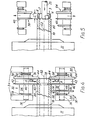
- the apparatus shown in Figures 2 to 5 is a profile rolling machine arranged to manufacture a succession of profiled bearing rings 3, one of which is indicated in Figure 5, direct from steel 'tube stock 10.
- Each ring 3 is a profiled roller for a rolling bearing, and has a spherical outer circumferential surface 4, merging with frusto-conical end surface portions 6 surrounding a cylindrical bore 7 of the ring.
- the apparatus shown in Figure 1 is a blank preparation machine for making a succession of annular workpieces or blanks 5, each having a cylindrical outer circumferential surface, from steel tube stock 10.
- Each of the blanks 5 is suitable for subsequent forming, in one or more separate machines, into a ring which may be generally similar to the ring 3 in Figure 5.
- this prior art machine is of the single-spindle type and has a chuck 11 of the conventional collet type, for supporting the tube stock 10.
- the latter is cantilevered from the chuck 11 on a central axis 62.
- Each tool head comprises a yoke, 13 and 16 respectively, which are movable radially towards and away from the central axis 62 by means of hydraulic actuators 14 and 17 respectively.
- Each yoke 13 or 16 has a respective transverse spindle or pin 50, 51 which carries a corresponding one of a pair of rotatable parting tool elements in the form of part-off rolling tools 12, 15 respectively.
- Each of the part-off rolling tools 12 and 15 is biassed by a disc spring or a Belleville washer 22 towards a left-hand or datum position from which it can be moved axially to the right (as seen in Figure 1) against its spring 22 by a limited amount.
- a tailstock or machining head 21 is provided opposite the chuck 11.
- the tailstock 21 is movable, towards and away from the latter in directions parallel to the axis 62, by means of an hydraulic actuator 33.
- the tailstock carries a cutting tool 24 to machine the outer circumferential surface of the ring 5, a boring tool (indicated at 25) to machine the bore of the ring, and a chamfering tool which is not visible.
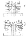
- the profile rolling machine shown in these Figures, and now to be described differs from that seen in Figure 1 only in the construction of the tooling, and in the aspects of its operation resulting from these differences.
- the profile rolling machine has the chuck 11 and the tailstock 21 with its actuator 33, though these two last-mentioned parts are not shown in Figures 2 to 5.
- the boring tool 25 is also present (see Figure 5), but the tool 24 of Figure 1 is absent from the profile rolling machine.
- the latter again has two tool heads, each comprising a yoke with a tool spindle or pin upon which the tool elements are mounted, and each having its yoke coupled to a tool.head actuator (such as 14, 17, but not shown in Figures 2 to 5) in the same manner as is shown in Figure 1.
- the tool heads comprise a primary tool head 30 and a secondary tool head 32, the yoke or body of each tool head being denoted by the reference numeral 34 and its tool spindle by 36.
- the tool spindles define respective tool axes parallel to the central axis 62.
- a unitary tool member 38 mounted on the tool spindle 36 of the secondary tool head 32, and freely rotatable on the latter, is a unitary tool member 38 in the form of a profiled roller of hardened steel suitable for performing cold rolling operations.
- the unitary roller 38 has three distinct portions, which, reading from left to right in Figures 2 to 5, comprise a parting tool element 40, a profile rolling tool element 42, and a thrust flange 44.
- the parting tool element 40 is V-shaped, terminating at its circumference in a relatively narrow, radiused edge 46.
- the angle subtended at the edge 46 by the frusto-conical flanks of the tool element 40 is, as can be seen, relatively small.
- the flank 47 of the element 40 adjacent to the rolling tool element 42 merges with the outer circumferential surface 48, constituting the profiled rolling tool surface, of the element 42.
- the rolling tool surface 48 is in this example of generally arcuate cross-section for forming the surface 4 of the finished ring 5 ( Figure 5); as has been mentioned, the surface 4 is spherical in form.
- the surface 48 merges with a generally frusto-conical flank 52 of the thrust flange 44.
- the angle subtended between the frusto-conical flanks 47 and 52 and the radial plane containing the outer circumference of the flank concerned, is the same in both cases. This ensures that, in the finished ring 5, the conical end faces 6 of the latter shall be identical with each other.
- the diameter of the flange 44 may be the same as that of the parting tool element 40, though it is not essential that these diameters be exactly the same.
- the unitary roller 38 is flanked by a bush 54 on one side and a bush 56 on the other.
- the bush 54 bears against one of the arms of the yoke 34 through a pair of disc springs (Belleville washers) 58, whilst the bush 56 similarly bears against the other arm of the yoke through a set 60 of further Belleville washers.
- the roller 38 (and particularly therefore the parting tool element 40) is mounted for limited axial movement, controlled by the resilience of the two sets of Belleville washers.
- the primary tool head 30 has a unitary roller 64 which is identical to the corresponding roller 38 of the secondary head 32.
- the roller 64 is mounted diametrically opposite to the roller 38, so defining a common diametral plane 66 ( Figure 2) containing the respective edges 46 of the parting tool elements.
- the roller 64 is again mounted on the corresponding tool spindle 36, for free rotation thereon, with another bush 56 and set 60 of Belleville washers between the roller and the right-hand arm of the corresponding yoke 34 as seen in Figures 2 to 5.
- the unitary roller 64 is spaced from the other arm of the yoke by a further pair 58 of Belleville washers, a bush 68, a grooving tool 70, and an intermediate spacer bush 72.
- the grooving tool 70 comprises a disc-like wheel of hardened steel to serve as a cold rolling tool, and is of smaller diameter than the adjacent parting tool element 40. It has a V-shaped working surface 74, which subtends an angle at the outer circumference having any suitable value for the purpose to be described below. In this example this angle is 45 0.
- the spacer bush 72 of the primary tool head is accurately machined to a length such that the effective axial distance L, ( Figure 2), between the circumferential edge of the grooving tool 70 and the common plane 66 containing the edge 46 of the parting tool element, has a fixed predetermined value which is equal to, or which bears a known relationship to the final axial length (ring width) L l of the finished ring 3 ( Figure 5).
- the grooving tool 70 is freely rotatable on its tool spindle 36.
- the chuck 11 has, associated with it, conventional means (not shown) for feeding cylindrical steel stock (in this example tube stock) 10 through it, along the central axis 62.
- This feeding means need not be described here; for a discussion of suitable feeding means reference is made to our aforementioned Patent Specification No. GB-2038213A. It is sufficient to mention here that the feeding means is adapted to index the stock 10 forward along the central axis 62 by increments approximately equal to the length L of the spacer bush 72, suitable stop means (not shown) being provided for halting the advance at the end of each increment.
- the chuck 11 is rotated continuously by conventional drive means (not shown), so as also to rotate the tube stock 10 continuously.
- the stock 10 is advanced by an increment, as mentioned above, and is held by the chuck in the axial position shown in Figure 2.
- a V-shaped locating groove 76 previously formed circumferentially on the outside of the stock 10 is intersected by the common plane 66 of the two parting tool elements 40.
- the annular end portion 78 of the stock 10 which extends from the centre of the locating groove 76 to the free end of the stock, has the same length L as the spacer bush 72. It is of course the end portion 78 which will now be formed into the profiled ring 3 seen in Figure 5.
- the hydraulic actuators of the tool heads 30, 32 are now operated so as to advance the tool heads simultaneously in radial directions towards the central axis 62, as indicated by the arrows R in Figure 3.
- the edges 46 of the parting tool elements 40 simultaneously reach the locating groove 76 upon continued radial movement the tool elements 40 become accurately located in the latter so that the common plane 66 then contains the bottom of the locating groove.
- the unitary rollers 38 and 60 may undergo slight axial movement, against the appropriate Belleville washers, in order to effect this adjustment.
- the grooving tool 70 undergoes the same movement, thus preserving, at this stage, the axial distance L between the tool 70 and the plane 66.
- annular end portion 78 is urged axially forward as indicated by the arrow X in Figure 3, until its free end engages the thrust flanks 52 of the unitary rollers.
- the end portion 78 is cold rolled between the two unitary rollers 38 and 64 so that its exterior surface is re-formed to the cross-section shown in Figures 4 and 5 (and already described herein). This cold rolling operation is performed by the profiled surfaces 47, 48 and 52 of the unitary rollers.
- the radial advance R of the tool heads is terminated when the profiled rolling operation has been completed, i.e. when the end portion 78 has a profile conforming with that of the abovementioned profiled surfaces of the unitary rollers.
- the locating groove 80 is also complete, whilst the parting groove has been formed to a depth such that complete severance of the end portion 78 from the remainder of the tube stock has not quite been achieved.
- the tool heads 30 and 32 are now radially retracted, and the boring tool 25 is introduced, as seen in Figure 5, to machine the bore of the end portion 78 to the required diameter to form the bore 7 of the finished ring 3.
- This operation also completes severance of the ring 3 from the tube stock; in this connection it will be realised that the relationship between the diameter of the parting tool elements 40 and the location of the profiled rolling tool surface 48 will have been determined accordingly.
- the finished ring 3 is removed by any suitable means (not shown), whereupon the machine is ready for the tube stock to be indexed axially forward once again for the making of the next ring.
- the profiled rings 3 can be further operated on if necessary, by further cold rolling operations or by machining (for example to form chamfers on the ends of the bore).
- rollers 38 and 64 need not be of unitary construction. Any one or more of the elements 40, 42 or 44 may be made as a separate member.
- the profile of the finished rings, as defined by the rolling surfaces of the tool elements, may take any desired form.
- any suitable number of tool heads may be provided, for example three or more. Whilst it is generally convenient for there to be as many profiled rolling tool surfaces (such as the surfaces 48) as there are tool heads, this is not essential provided proper "back-up" support is provided. The same is true for the parting tool elements. In the latter case, our Patent Specification No. GB-2038213A describes an alternative arrangement in which there is a single parting tool which is carried by one tool head, with a simple back-up roll, radially opposite the parting tool provided as part of the other tool heads.
- the end stop means providing an axial thrust surface for the free end of the stock should necessarily be a part of the rotating tool assembly, as for example the rollers 38 and 64.
- a fixed stop plate or ring could be mounted, in the axial position occupied by the flanges 44 in Figure 4, between the two tool heads.
- Such a plate or ring will have a suitable aperture to permit the boring tool 25 to pass through it, and may be carried by the main frame of the machine.
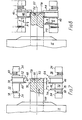
- the method and apparatus therein illustrated are adapted for the substitution of solid bar stock 110 for the tube stock 10.
- the bore of the finished ring, 103 in Figure 11 is formed by conventional drilling, which involves substantial loss of material. Nevertheless, this may be preferable on economic grounds to the use of tube stock where the ring 103 is to be of relatively small diameter.
- the apparatus of Figures 6 to 11 is the same as that shown in Figures 2 to 5 except (a) insofar as any dimensions may require to be different in order to provide for a difference between the diameters of the tube stock 10 and bar stock 110, or any designed dimensional differences between the finished rings 3 and 103; and (b) insofar as the tailstock assembly shown in Figure 6 differs from the equivalent part (illustrated in Figure 1) of the apparatus for working on tube stock.
- the tailstock or machining head is indicated at 121; it differs from the tailstock 21 of Figure 1 in having a turret 122 which carries, besides the boring tool 25, a drill 123. By suitable rotation of the turret 122, the drill 123 can be aligned with the central axis 62.
- the depth of the parting groove formed.by the tool elements 40 in this example is insufficient for the drill 123 to effect final separation of the ring 103 from the bar stock; however, the tooling can if desired be so dimensioned that the drill will in fact effect such separation.
- the drill 123 is withdrawn, and after rotating the turret 122 ( Figure 6) appropriately, the boring tool 25 is introduced (Figure 11) to effect final separation in the same manner as was shown in Figure 5.
- the formation of a bore by drill 123 may if desired be performed before the tool heads 30 and 32 are advanced for forming the parting groove and the second locating groove 80.
Landscapes
- Engineering & Computer Science (AREA)
- General Engineering & Computer Science (AREA)
- Mechanical Engineering (AREA)
- Manufacturing & Machinery (AREA)
- Turning (AREA)
- Rolling Contact Bearings (AREA)
Applications Claiming Priority (2)
| Application Number | Priority Date | Filing Date | Title |
|---|---|---|---|
| GB08320885A GB2144351B (en) | 1983-08-03 | 1983-08-03 | Making rings from tube or bar stock |
| GB8320885 | 1983-08-03 |
Publications (3)
| Publication Number | Publication Date |
|---|---|
| EP0133765A2 true EP0133765A2 (fr) | 1985-03-06 |
| EP0133765A3 EP0133765A3 (en) | 1985-08-21 |
| EP0133765B1 EP0133765B1 (fr) | 1987-12-23 |
Family
ID=10546722
Family Applications (1)
| Application Number | Title | Priority Date | Filing Date |
|---|---|---|---|
| EP84304974A Expired EP0133765B1 (fr) | 1983-08-03 | 1984-07-20 | Fabrication d'anneaux à partir de tubes ou d'acier en barres |
Country Status (5)
| Country | Link |
|---|---|
| US (1) | US4612789A (fr) |
| EP (1) | EP0133765B1 (fr) |
| JP (2) | JPS6071109A (fr) |
| DE (1) | DE3468182D1 (fr) |
| GB (1) | GB2144351B (fr) |
Cited By (2)
| Publication number | Priority date | Publication date | Assignee | Title |
|---|---|---|---|---|
| DE19526900A1 (de) * | 1995-07-22 | 1997-01-23 | Univ Dresden Tech | Verfahren zur kombinierten spanenden und umformenden Fertigung von Ringen und Maschinen hierzu |
| EP2036642A3 (fr) * | 2007-09-12 | 2011-10-12 | Walter Möck | Dispositif d'usinage mécanique de la circonférence de pièces à usiner en forme d'anneau ou de douille |
Families Citing this family (16)
| Publication number | Priority date | Publication date | Assignee | Title |
|---|---|---|---|---|
| WO1993016305A1 (fr) * | 1992-02-18 | 1993-08-19 | Federal-Mogul Corporation | Manchons d'usure destines a des joints pour lubrifiants |
| US5860305A (en) * | 1997-04-15 | 1999-01-19 | Lindab Ab | Pipe cutter with dual outer cutting knives and method |
| RU2127643C1 (ru) * | 1997-07-29 | 1999-03-20 | Закрытое акционерное общество Научно-производственная фирма "Имекс" | Способ изготовления металлопроката |
| DE19734563C1 (de) * | 1997-08-04 | 1998-12-03 | Mannesmann Ag | Verfahren zur Herstellung von Wälzlagerringen aus Stahl |
| US6192726B1 (en) | 1999-11-05 | 2001-02-27 | Lindab Ab | System and method for corrugating spiral formed pipe |
| US6295853B1 (en) | 2000-02-18 | 2001-10-02 | Lindab Ab | Spirally formed pipe cutter with driving mechanism to actively rotate inner knife |
| DE10331061B4 (de) * | 2003-07-09 | 2005-05-19 | Technische Universität Dresden | Ringförmige Verbundwerkstücke und Kaltwalzverfahren zu ihrer Fertigung |
| EP1656225B1 (fr) * | 2003-08-13 | 2015-04-22 | Technische Universität Dresden | Procede de fabrication d'anneaux profiles a l'interieur et/ou a l'exterieur et dispositif destine a cet effet |
| DE102005028828B3 (de) * | 2005-06-15 | 2006-12-21 | Getrag Synchrontechnik Gmbh | Verfahren und Vorrichtung zum Herstellen von Metallringen |
| JP2006348587A (ja) * | 2005-06-16 | 2006-12-28 | Hitachi Metals Techno Ltd | 梁貫通孔補強材 |
| US20080089751A1 (en) * | 2006-10-11 | 2008-04-17 | Physical Systems, Inc. | Sleeve cutter |
| KR101430331B1 (ko) * | 2010-08-04 | 2014-08-13 | 닛본 세이고 가부시끼가이샤 | 볼 나사용 너트의 제조방법 및 볼 나사 |
| US8356506B2 (en) * | 2011-02-25 | 2013-01-22 | Szuba Consulting, Inc. | Method of forming industrial housings |
| DE102016107240A1 (de) * | 2016-04-19 | 2017-10-19 | Hoerbiger Antriebstechnik Holding Gmbh | Verfahren zur Herstellung einer Schiebemuffe für eine Schaltgetriebe-Synchronbaugruppe sowie mittels des Verfahrens hergestellte Schiebemuffe |
| JP6466371B2 (ja) * | 2016-07-07 | 2019-02-06 | 透一 野渡 | リング状部品の製造方法及び製造装置 |
| CN109702067B (zh) * | 2018-12-26 | 2023-11-10 | 浙江长兴和良智能装备有限公司 | 一种管件旋压方法及结构改进的旋压机 |
Family Cites Families (10)
| Publication number | Priority date | Publication date | Assignee | Title |
|---|---|---|---|---|
| DE50937C (de) * | J. MUNTON in Maywosd, Cook, Illinois, V. St. A | Walzwerk zum gleichzeitigen Walzen mehrerer Radreifen aus einem Block | ||
| US819844A (en) * | 1904-10-04 | 1906-05-08 | Otto Briede | Manufacture of nuts. |
| US1839909A (en) * | 1929-10-28 | 1932-01-05 | Jr Albert J Weatherhead | Method of producing pipe couplings |
| US3756055A (en) * | 1969-12-15 | 1973-09-04 | Rotary Profile Anstalt | Apparatus for rolling workpieces |
| GB1395726A (en) * | 1971-10-22 | 1975-05-29 | Formflo Ltd | Rolling machines |
| JPS5135783B2 (fr) * | 1972-06-11 | 1976-10-05 | ||
| US3883943A (en) * | 1973-11-21 | 1975-05-20 | Black & Decker Mfg Co | Process of manufacturing drill chucks |
| CS220401B1 (en) * | 1973-12-04 | 1983-04-29 | Karel Sommer | Method of manufacturing hollow circular workpieces |
| GB1535562A (en) * | 1976-06-15 | 1978-12-13 | Formflo Ltd | Preparation of annular blanks from tube stock |
| GB2038213B (en) * | 1978-12-27 | 1982-09-29 | Formlo Ltd | Making rings from tube stock |
-
1983
- 1983-08-03 GB GB08320885A patent/GB2144351B/en not_active Expired
-
1984
- 1984-07-20 EP EP84304974A patent/EP0133765B1/fr not_active Expired
- 1984-07-20 DE DE8484304974T patent/DE3468182D1/de not_active Expired
- 1984-07-30 US US06/636,007 patent/US4612789A/en not_active Expired - Lifetime
- 1984-07-31 JP JP59161475A patent/JPS6071109A/ja active Pending
-
1987
- 1987-09-08 JP JP1987136365U patent/JPH039938Y2/ja not_active Expired
Cited By (3)
| Publication number | Priority date | Publication date | Assignee | Title |
|---|---|---|---|---|
| DE19526900A1 (de) * | 1995-07-22 | 1997-01-23 | Univ Dresden Tech | Verfahren zur kombinierten spanenden und umformenden Fertigung von Ringen und Maschinen hierzu |
| DE19526900B4 (de) * | 1995-07-22 | 2005-07-14 | Technische Universität Dresden | Verfahren zur kombinierten spanenden und umformenden Fertigung von Ringen und Maschinen hierzu |
| EP2036642A3 (fr) * | 2007-09-12 | 2011-10-12 | Walter Möck | Dispositif d'usinage mécanique de la circonférence de pièces à usiner en forme d'anneau ou de douille |
Also Published As
| Publication number | Publication date |
|---|---|
| JPS6071109A (ja) | 1985-04-23 |
| JPS6357020U (fr) | 1988-04-16 |
| EP0133765B1 (fr) | 1987-12-23 |
| DE3468182D1 (en) | 1988-02-04 |
| GB8320885D0 (en) | 1983-09-07 |
| EP0133765A3 (en) | 1985-08-21 |
| GB2144351B (en) | 1986-09-03 |
| GB2144351A (en) | 1985-03-06 |
| US4612789A (en) | 1986-09-23 |
| JPH039938Y2 (fr) | 1991-03-12 |
Similar Documents
| Publication | Publication Date | Title |
|---|---|---|
| US4612789A (en) | Making rings from tube or bar stock | |
| EP0013832B1 (fr) | Procédé et dispositif pour la fabrication de bagues à partir de tubes | |
| US4126064A (en) | Preparation of annular blanks from tube stock | |
| EP2167275B1 (fr) | Station de meulage et procede de meulage simultane de plusieurs paliers de vilebrequin | |
| CN101733319B (zh) | 旋转挤压成形方法及其模具 | |
| DE102006024715A1 (de) | Verfahren zum Bearbeiten der Lagersitze der Haupt- und Hublager von Kurbelwwellen | |
| DE102011113758A1 (de) | Verfahren und Vorrichtung zur Fertigbearbeitung von Werkstücken | |
| DE19526900B4 (de) | Verfahren zur kombinierten spanenden und umformenden Fertigung von Ringen und Maschinen hierzu | |
| CN201603769U (zh) | 旋转挤压成形模具 | |
| EP1824627B1 (fr) | Procédé et machine pour usiner des logements de paliers d'arbres | |
| US4841682A (en) | Process and device for producing turned parts from rods or bars | |
| US5355706A (en) | Process for the production of a hollow workpiece being profiled at least internally in a straight or helical manner relative to the workpiece axis | |
| US4116032A (en) | Method and apparatus for manufacturing straight or inclined toothed machine elements, especially spur gears by cold working | |
| EP0885082B1 (fr) | Procede et dispositif pour usiner des logements de palier de vilebrequins | |
| EP0552776B1 (fr) | Procédé de roulage pour la fabrication de poulies à gorge unique ou multiple en forme de V et à roue phonique intégrale | |
| US4805431A (en) | Contrivance for the cutting-deforming of cylindrical surfaces | |
| US2170631A (en) | Bearingizing tool | |
| DE19833363A1 (de) | Verfahren zur Drehbearbeitung von Rotationsflächen an Werkstücken, vorzugsweise an Kurbelwellen, und scheibenförmiges Werkzeug zur Durchführung des Verfahrens | |
| US2219694A (en) | Machine for making shafts | |
| RU2722940C1 (ru) | Способ обтачивания наружной поверхности прецизионной длинномерной трубы | |
| CN103464785A (zh) | 杆状工件的车削切断方法 | |
| US3293988A (en) | Method and apparatus for broaching gears | |
| US5230234A (en) | Method of making roll-finished gears | |
| CN115255838A (zh) | 一种穿滚滚丝轮制作工艺及方法 | |
| WO1998032556A1 (fr) | Procede pour realiser des bagues par enlevement de matiere et formage combines, et machine correspondante |
Legal Events
| Date | Code | Title | Description |
|---|---|---|---|
| PUAI | Public reference made under article 153(3) epc to a published international application that has entered the european phase |
Free format text: ORIGINAL CODE: 0009012 |
|
| 17P | Request for examination filed |
Effective date: 19840727 |
|
| AK | Designated contracting states |
Designated state(s): DE FR IT SE |
|
| PUAL | Search report despatched |
Free format text: ORIGINAL CODE: 0009013 |
|
| AK | Designated contracting states |
Designated state(s): DE FR IT SE |
|
| 17Q | First examination report despatched |
Effective date: 19870310 |
|
| GRAA | (expected) grant |
Free format text: ORIGINAL CODE: 0009210 |
|
| AK | Designated contracting states |
Kind code of ref document: B1 Designated state(s): DE FR IT SE |
|
| REF | Corresponds to: |
Ref document number: 3468182 Country of ref document: DE Date of ref document: 19880204 |
|
| ITF | It: translation for a ep patent filed | ||
| ET | Fr: translation filed | ||
| PLBE | No opposition filed within time limit |
Free format text: ORIGINAL CODE: 0009261 |
|
| STAA | Information on the status of an ep patent application or granted ep patent |
Free format text: STATUS: NO OPPOSITION FILED WITHIN TIME LIMIT |
|
| 26N | No opposition filed | ||
| ITTA | It: last paid annual fee | ||
| EAL | Se: european patent in force in sweden |
Ref document number: 84304974.3 |
|
| PGFP | Annual fee paid to national office [announced via postgrant information from national office to epo] |
Ref country code: FR Payment date: 20030609 Year of fee payment: 20 |
|
| PGFP | Annual fee paid to national office [announced via postgrant information from national office to epo] |
Ref country code: SE Payment date: 20030623 Year of fee payment: 20 |
|
| PGFP | Annual fee paid to national office [announced via postgrant information from national office to epo] |
Ref country code: DE Payment date: 20030625 Year of fee payment: 20 |
|
| EUG | Se: european patent has lapsed |