EP0133293A2 - Two-component package - Google Patents
Two-component package Download PDFInfo
- Publication number
- EP0133293A2 EP0133293A2 EP84108855A EP84108855A EP0133293A2 EP 0133293 A2 EP0133293 A2 EP 0133293A2 EP 84108855 A EP84108855 A EP 84108855A EP 84108855 A EP84108855 A EP 84108855A EP 0133293 A2 EP0133293 A2 EP 0133293A2
- Authority
- EP
- European Patent Office
- Prior art keywords
- cup
- collar
- wall
- component
- neck
- Prior art date
- Legal status (The legal status is an assumption and is not a legal conclusion. Google has not performed a legal analysis and makes no representation as to the accuracy of the status listed.)
- Granted
Links
Images


Classifications
-
- B—PERFORMING OPERATIONS; TRANSPORTING
- B65—CONVEYING; PACKING; STORING; HANDLING THIN OR FILAMENTARY MATERIAL
- B65D—CONTAINERS FOR STORAGE OR TRANSPORT OF ARTICLES OR MATERIALS, e.g. BAGS, BARRELS, BOTTLES, BOXES, CANS, CARTONS, CRATES, DRUMS, JARS, TANKS, HOPPERS, FORWARDING CONTAINERS; ACCESSORIES, CLOSURES, OR FITTINGS THEREFOR; PACKAGING ELEMENTS; PACKAGES
- B65D51/00—Closures not otherwise provided for
- B65D51/24—Closures not otherwise provided for combined or co-operating with auxiliary devices for non-closing purposes
- B65D51/28—Closures not otherwise provided for combined or co-operating with auxiliary devices for non-closing purposes with auxiliary containers for additional articles or materials
- B65D51/2807—Closures not otherwise provided for combined or co-operating with auxiliary devices for non-closing purposes with auxiliary containers for additional articles or materials the closure presenting means for placing the additional articles or materials in contact with the main contents by acting on a part of the closure without removing the closure, e.g. by pushing down, pulling up, rotating or turning a part of the closure, or upon initial opening of the container
- B65D51/2814—Closures not otherwise provided for combined or co-operating with auxiliary devices for non-closing purposes with auxiliary containers for additional articles or materials the closure presenting means for placing the additional articles or materials in contact with the main contents by acting on a part of the closure without removing the closure, e.g. by pushing down, pulling up, rotating or turning a part of the closure, or upon initial opening of the container the additional article or materials being released by piercing, cutting or tearing an element enclosing it
- B65D51/2842—Closures not otherwise provided for combined or co-operating with auxiliary devices for non-closing purposes with auxiliary containers for additional articles or materials the closure presenting means for placing the additional articles or materials in contact with the main contents by acting on a part of the closure without removing the closure, e.g. by pushing down, pulling up, rotating or turning a part of the closure, or upon initial opening of the container the additional article or materials being released by piercing, cutting or tearing an element enclosing it said element being provided with a preformed weakened line
Definitions
- the invention relates to a two-component pack with a cup arranged in the pack neck for receiving the one component and a screw cap assigned to the pack neck with a collar protruding into the cup, the end edge of which forms a butt edge for separating the cup in the area of a predetermined breaking line by another Unscrew the screw cap beyond the basic sales position.
- a two-component pack of this type is known from GB-PS 1 083 335.
- the cylindrical collar formed centrally on the screw cap cover and the base of the cup extending in front of it form the actual receiving chamber of the one component.
- the predetermined breaking line lies in the bottom edge zone. In the basic sales position, the front edge lies there.
- the one component is powdery material.
- the sealing relationships between the cup and the collar take this into account accordingly.
- Such a package is therefore less suitable for liquid components; For example, due to the capillary action in the joint between the cup and neck, a not inconsiderable proportion of the mixture would be removed.
- a similar two-component pack is known from GB-PS 15 57 521, but which has no screw cap.
- the separation of the cup is effected by the rotary movement of the cap and the lower part is practically stalled.
- relatively complicated means have to be used, namely primarily a special design of the bottle neck.
- the bottle neck forms axially lying ribs on the inside.
- the distance between the individual ribs leads to engagement grooves for cup-like, strip-like projections.
- the latter sit on the lower, detachable part of the cup.
- This detachable part is held against rotation by the meshing of the ribs or strips.
- the upper part of the cup is in rotational engagement with the clipped-on cap. Similar coupling agents are used for this.
- This configuration is complicated and expensive to manufacture.
- the cup is bound to very specific container shapes (which have the necessary countermeasures in the neck).
- a two-component pack of particularly high utility value is achieved: because the predetermined breaking line is now provided at a distance from the cup bottom, the collar no longer exerts a compressive effect like a piston; rather, the collar only runs a short distance inside the cup.
- This has significant advantages, especially for automatic filling. Since the predetermined breaking point is formed by a ring step of the cup jacket wall lying in the cup, the best conditions result for the separation of the cup. The corresponding forces of the collar act directly on the ring step from above, i.e. in the most stable plane of the cup.
- the abutting edge of the collar is approximately flush with the ring step of the cup wall.
- the upper section of the cup which is wider in cross section, serves as a guide surface for the collar. This means that there can be no different loads in the area of the predetermined breaking line.
- the cup itself is held securely in the neck. It is also advantageous that the cup is conical at least below the ring step.
- the ring step is located approximately at half the height of the cup, this results in advantageous stackability of the cups. This is particularly favorable for magazine storage, of course also for warehousing and Shipping.
- a safe fixing of the cup also results from the fact that the cup wall is tied in the pack neck via a clip step located near the mouth of the packing neck and the outer surface of the cup wall runs below the clip step at a distance from the inner surface of the pack neck. The distance there provides advantageous radial flexibility, which benefits the seal between the collar and the cup.
- the position of the clip step that is as close as possible to the mouth brings the advantageous effect of the tight closure only at the last moment of the cup assignment.
- the screw cap itself is also held in clips on the pack.
- the procedure is such that the screw cap locks behind a clip shoulder of the neck in the basic sales position and the lowest area of the screw thread is composed of individual threaded cams lying one behind the other in the circumferential direction with an interruption.
- This interrupted pre-thread allows the cap to be simply pressed on, the thread cams being skipped by the internal thread of the screw cap, until the clip point is reached.
- the one-sided flank support of the thread given by the pre-thread favors the tilt-free screwing on of the cap.
- the cams are advantageously lenticular and of different heights. This measure also favors the bouncing of the screw cap. In the basic sales position reached, the butt edge of the collar is still at a distance from the ring step.
- the clip step and the clip shoulder are arranged approximately on the same cross-sectional plane.
- the material that is displaced outwards can be used to form the clip shoulder (simple material shift).
- the ring step by a bridge between two in the radial Sections of the cup jacket wall lying offset from one another are formed.
- the corresponding jacket wall offset can easily be generated by injection molding.
- an offset dimension is advantageously used, which corresponds approximately to the thickness of the jacket wall.
- the height of the offset edges one of which represents the ring step on the inside of the cup, determines the tear resistance of the material bridge.
- the invention further proposes that the bead of the cup wall be gripped behind by a clip shoulder of the collar.
- the closing path does not have to be covered again to release the filling contents; rather, the predetermined breaking point is destroyed when the cap is completely screwed on to the larger-volume packaging.
- the cup wall on its outer surface, adjacent to the cup-bottom section forms a support wall which arises from the section lying in front of the predetermined breaking point and extends to the level of the cup bottom underside .
- Such a support wall acts as a spacer and keeps the detachable portion of the cup free from assembly loads.
- the supporting wall can advantageously be formed by a closed ring collar, as a result of which the closing loading forces are distributed over the entire cross-sectional wall cross section.
- the jacket wall of the cup wall carries spacer ribs. The latter provide a balanced support in the bottle neck, but on the other hand stabilize the cup itself in an advantageous manner.
- the edge of the cup forms an upwardly open annular groove. The edge becomes relatively flexible, which helps to achieve the tightly fitting seat.
- an advantageous embodiment is the same as several in the height direction other beads on the cup wall are reached. Such beads define, for example, different interlocking depths, with each securing of the inserted plug position. They also let air escape when skipping.
- the two-component pack holds one component I in a cup 2 inserted into the pack neck 1 and the other component 11 in the larger-volume pack 3.
- a screw cap 4 designed as a closure serves as a separating tool.
- the cup 2 which is made of plastic, forms an outwardly directed edge 5 in its upper, essentially cylindrical section. This overlaps the corresponding end edge 1 'of the packing neck 1.
- the edge 5 does not protrude outwards and defines the hanging depth of the cup 2.
- the latter is, however, additionally secured against falling out.
- the cup wall W is tied in the pack neck via a clip step St located near the mouth 6 of the pack neck 1.
- This clip level is realized by an annular rib 7 on the outer surface of the cup jacket wall W, which annular rib 7 engages in a shape-matching annular groove 8 on the inner surface of the packing neck 1.
- the outer surface of the cup jacket wall W runs below the clip step St at a distance x from the inner surface of the packing neck 1 (see FIG. 7). This allows the cup 2 to be inserted easily.
- the sealing assignment arises only at the last moment of the insertion assignment, with friction occurring between the annular rib 7 and the cylindrical inner surface of the packing neck 1. Due to the proximity to the mouth 6, this zone of increased friction is considerably reduced; there is also no significant compression in the interior of the pack when assigning the cups. Even a little compression would not be able to push the cup out again. The clip forces are adjusted accordingly.
- the latter is formed by an annular step A of the cup jacket wall W lying in the cup and at a distance y from the cup base 2 ".
- the abutting edge 9 'of a collar 9 of the screw cap 4 which enters the cup from above meets the latter.
- the latter is rooted in the screw cap cover 10 and is designed as a cylindrical ring wall, the abutting edge extends perpendicular to the longitudinal center axis zz of the rotationally symmetrical two-component pack.
- the collar 9 continues upwards into a muzzle tube 11 which tapers continuously towards the free end. Its mouth opening 12 is kept closed by a molded plug 13. It is a tamper-evident seal.
- the abutting edge 9 'of the collar 9 is essentially flush with the ring step A of the cup jacket wall W.
- the distance dimension y corresponds to approximately 2/3 of the height of the cup 2.
- the outer surface of the collar 9 is sealed to the inner surface of the cup wall in the basic sales position by a bead 14 located near the collar edge 9 '.
- the bead 14 is as close as possible to the abutting edge 9 ', so that here, too, when the screw cap is assigned, the friction and sealing are only present at the last moment, so that the screw cap 4 cannot be braced against the internal pressure which forms. There is also a safety precaution. The latter is that the screw cap 4 locks in the basic sales position behind a clip shoulder 15 of the packing neck 1.
- the clip shoulder 15 extends approximately on the same cross-sectional plane as the clip step St.
- the shoulder-forming wall section consists practically or in part of the displacement material of the annular groove 8.
- the counter-shoulder 16 on the screw cap side is an annular rib directed towards the cap.
- the lens shape brings both in the direction of rotation of the screw cap 4 and in the transverse direction of the same (cap attachment direction) convex curves.
- the distance between them corresponds approximately to a cam length.
- a total of 8 cams extend over the circumference. They have different heights, so that the transfer of the external thread 18 is facilitated when bouncing or screwing on. For screwing on there is the advantage of a tilt-free assignment of the screw cap 4.
- the offset of the wall sections 2 "and 2" 'to each other corresponds to slightly more than the thickness of the cup jacket wall W. Both jacket wall sections overlap one another in the area of the material bridge 21. The degree of overlap corresponds to approximately one fifth of the thickness of the jacket wall. Below the ring step A, the cup 2 is frustoconical.
- the two-component pack according to the second embodiment is basically of the same structure; the reference numerals are, insofar as is necessary for understanding, correspondingly entered in FIGS. 10 to 12.
- the lateral surface of the cup wall W has spacing ribs 22 which extend in the insertion direction of the cup 2 and which clamp against the inner wall of the packing neck 1 and thus provide good rotational security.
- spacer ribs 22 stiffen the cup wall W.
- the rib width corresponds to the intermediate rib-free zone.
- the spacing ribs 22 run into a diverging edge section 5 ', forming a frustoconical contact surface, which dips sealingly into the neck 1 and, due to an upwardly open annular groove 23, is particularly elastic.
- the annular groove is, seen in cross-section, notch-valley-shaped with an obliquely outward flank and a steep, i.e. H. Flank running concentrically to the longitudinal center axis z-z of the rotationally symmetrical two-component pack.
- the butt edge 9 ′ which is essentially aligned with the ring step A of the cup wall W, extends in the area on the left in FIG. 12 benen position at a closer distance to the ring step A than in Fig. 6, so that therefore a flatter small package is achieved.
- the cup wall W forms at least one annular bead 14 on the inside.
- the latter extends horizontally in the vicinity of the ring step A and is engaged behind by an annular clip shoulder 24 formed onto the outer surface of the collar 9.
- This clip shoulder located at a short distance from the free end of the collar 9, is resilient when the cup and screw cap are connected.
- three beads 14 of the cup wall lying one above the other in the vertical direction are formed on the inside. The distance between the beads 14 corresponds approximately to twice the width of a bead, which beads also provide a good seal in addition to the axial fixing of the parts forming a capsule.
- the screw cap according to FIG. 11 is placed on the back.
- the upwardly facing collar 9 thus forms a cup-like filling space on the inside.
- the cup is then assigned with the cup opening facing downwards.
- the clip shoulder 24 successively overflows one or more beads 14 defining the insertion depth.
- the cup wall W In order to keep away any impairment from the bottom-side section 2 "connected to the upper section 2"'of the cup via the predetermined breaking line during this assembly, the cup wall W, adjacent to the cup-bottom side section 2 ", continues into a support wall 25.
- the support wall arises from the area of the predetermined breaking point and is advanced to the level of the bottom side of the bottom of the cup 26.
- the end face 25 ' can even protrude slightly from the bottom of the bottom 26 of the cup does not come to the bottom of the cup bottom 26 even with a slight axial compression of the casing wall.
- a further protective cover can also be used, namely the essentially cylindrical cup wall 27 of the screw cap 4 by the End face 25 'of the support wall 25 is brought into alignment, ie level with the end wall 27' of the cap wall 27. With this full immersion position, the small annular gap between the abutting edge 9 'of the collar 9 is retained. In addition, there remains a distance D between the top 5 ′′ of the collar 9 and the corresponding inner surface 10 ′ of the screw cap cover 10.
- the spacer ribs 22 terminate at the same height as the end face 25 ', so that the contact surface is enlarged by the end faces of the spacer ribs.
- the capsule of the larger-volume, for example water-containing package 3 is also assigned here under the threaded engagement 16/18 of screw cap 4 and bottle neck 1.
- the thread engagement between the screw cap 4 and the packing neck is of such a length that the lower section 2 "of the cup 2 is cut off while screwing on, whereas the upper section 2 "'remains in the bottle neck.
- the film hinge-like material bridge 21 is torn between the two sections 2 "and 2" 'of the cup wall W which are offset from one another in the radial direction.
- the separated cup section 2 "falls into the package 3. Both components can now be mixed well by shaking.
- the detached container section 2" also serves as a shaking mixing body. The tight seal between the collar and the cup wall is maintained during shaking.
- the mixed substance can be dispensed.
Landscapes
- Engineering & Computer Science (AREA)
- Mechanical Engineering (AREA)
- Closures For Containers (AREA)
Abstract
Description
Die Erfindung bezieht sich auf eine Zwei-Komponenten-Packung mit im Packungshals angeordnetem Becher zur Aufnahme der einen Komponente und einer dem Packungshals zugeordneten Schraubkappe mit einem in den Becher ragenden Kragen, dessen Stirnrand eine Stoßkante bildet zum Zertrennen des Bechers im Bereich einer Sollbruchlinie durch weiteres Aufschrauben der Schraubkappe über die Verkaufsgrundstellung hinaus.The invention relates to a two-component pack with a cup arranged in the pack neck for receiving the one component and a screw cap assigned to the pack neck with a collar protruding into the cup, the end edge of which forms a butt edge for separating the cup in the area of a predetermined breaking line by another Unscrew the screw cap beyond the basic sales position.
Eine Zwei-Komponenten-Packung dieser Art ist durch die GB-PS 1 083 335 bekannt. Der der Schraubkappendecke zentral angeformte, zylindrische Kragen und der sich davor erstreckende Boden des Bechers bilden die eigentliche Aufnahmekammer der einen Komponente. Die Sollbruchlinie liegt in der Bodenrandzone. In Verkaufsgrundstellung liegt der Stirnrand dort auf. Gemäß dem erläuterten Ausführungsbeispiel handelt es sich bezüglich der einen Komponente um pulverförmiges Gut. Die Dichtungsverhältnisse zwischen Becher und Kragen berücksichtigen dies entsprechend. Eine solche Packung ist daher für flüssige Komponente weniger geeignet; beispw. aufgrund der Kapillarwirkung in der Fuge zwischen Becher und Hals würde ein nicht unbeträchtlicher Anteil der Mischung entzogen werden. Darüber hinaus bestehen auch in baulicher Hinsicht Nachteile insofern, als ein auf die Verhältnisse flüssiger Medien abgestimmter Dichtschluß die Zuordnung des Deckels erschwert zufolge der Komprimierung der eingeschlossenen Luft. Schließlich ergibt sich auch für die Ausgabe der Mischung ein Nachteil insofern, als der als Scheibe anfallende Boden sich möglicherweise sperrend vor die Ausschüttöffnung legt. Endlich läßt sich die erforderliche Sollbruchlinie auf Höhe des Bodens praktisch nur in werkzeugaufwendiger Weise realisieren. Schon geringe Toleranzabweichungen können dazu führen, daß allein durch die Zuordnung der Schraubkappe mangels eines spürbaren Widerstandes der Boden schon abgetrennt wird. Der Verpackungsinhalt wird so möglicherweise unbemerkt schon unbrauchbar. Andererseits ist eine zu harte Ansprechschwelle für den Gebrauch nachteilig insofern, als ungewohnte Schraubbetätigungskräfte aufgewendet werden müssen. Möglicherweise kommt es dabei lediglich zu einem leichten Ausbeulen des Bodens und nicht zu der gewünschten Abtrennung.A two-component pack of this type is known from GB-
Weiter ist eine ähnliche Zwei-Komponenten-Packung durch die GB-PS 15 57 521 bekannt, welche aber keine Schraubkappe hat. Das dortige Trennprinzip ist daher anderer Art. Dort wird die Trennung des Bechers durch reine Drehbewegung der Kappe bewirkt und so der untere Teil praktisch abgewürgt. Dazu sind verhältnismäßig komplizierte Mittel anzuwenden, nämlich in erster Linie eine spezielle Ausgestaltung des Flaschenhalses. Der Flaschenhals bildet innenseitig axial liegende Rippen aus. Der Abstand zwischen den einzelnen Rippen führt zu Eingriffsnuten für becherseitige, leistenartige Vorsprünge. Letztere sitzen am unteren, abtrennbaren Teil des Bechers. Dieser abtrennbare Teil wird gegen Drehmitnahme durch den Ineinandergriff der Rippen bzw. Leisten festgehalten. Der obere Teil des Bechers befindet sich in drehmitnehmendem Eingriff zur aufgeklipsten Kappe. Hierzu sind ähnliche Kupplungsmittel verwendet. Diese Ausgestaltung ist kompliziert und fertigungsaufwendig. Der Becher ist an ganz bestimmte Behälterformen gebunden (die im Hals die erforderlichen Gegenhaltemittel aufweisen).Furthermore, a similar two-component pack is known from GB-
Es bleibt danach die Aufgabe zu lösen, eine gattungsgemäße Zwei-Komponenten-Packung so auszubilden, daß bei erleichterter, einfacherer Herstellung eine im Hinblick auf das Zertrennen gebrauchsgünstigere Anordnung geschaffen wird und bei der auch die die Abdichtung bringenden Kräfte nicht in Trennrichtung des Bechers wirken. Gelöst ist diese Aufgabe durch die im Anspruch 1 angegebene Erfindung.It remains the task to solve a generic two-component pack so that with easier, simpler manufacture a more convenient in terms of cutting arrangement is created and in which the sealing forces do not act in the direction of separation of the cup. This object is achieved by the invention specified in
Die Unteransprüche sind vorteilhafte Weiterbildungen der erfindungsgemäßen Zwei-Komponenten-Packung.The subclaims are advantageous developments of the two-component pack according to the invention.
Zufolge solcher Ausgestaltung ist eine Zwei-Komponenten-Packung von insbesondere erhöhtem Gebrauchswert erzielt: Dadurch, daß die Sollbruchlinie nun in einem Abstand vom Becherboden vorgesehen ist, übt der Kragen nicht mehr eine komprimierende Wirkung wie ein Kolben aus; der Kragen durchläuft vielmehr eine nur kurze Strecke im Becherinneren. Das hat wesentliche Vorteile insbesondere auch für die automatische Füllung. Da die Sollbruchstelle von einer bechereinwärts liegenden Ringstufe der Bechermantelwand gebildet ist, ergeben sich beste Voraussetzungen für das Zertrennen des Bechers. Die entsprechenden Kräfte des Kragens wirken direkt von oben auf die Ringstufe, also in der stabilsten Ebene des Bechers. In vorteilhafter Weise setzt die Stoßkante des Kragens etwa fluchtend auf die Ringstufe der Becherwand auf. Der querschnittsbreitere, obere Abschnitt des Bechers dient dabei als Führungsfläche für den Kragen. Es kann so nicht zu unterschiedlichen Belastungen im Bereich der Sollbruchlinie kommen. Zudem erweist es sich als zuordnungsgünstig, daß die Mantelfläche des Kragens über einen nahe der Kragenstoßkante liegenden Wulst zur Innenfläche der Becher-Mantelwand hin in Verkaufsgrundstellung abgedichtet ist. Dadurch läßt sich der Anfangsbereich leichtgängig durchlaufen; die Dichtwirkung tritt erst im letzten Augenblick auf. Die dann auftretende Komprimierung im Becherinnenraum ist nur gering. Die erzielte Dichtigkeit führt sogar zu einer isoliert aufbewahrbaren Kleinpackung für die eine Komponente. Der Becher selbst ist sicher im Hals gehalten. Weiter ist es vorteilhaft, daß der Becher zumindest unterhalb der Ringstufe kegelförmig gestaltet ist. Bei etwa auf halber Becherhöhe liegender Ringstufe ergibt sich hieraus eine vorteilhafte Übereinanderschachtelbarkeit der Becher. Dies ist vor allem für die Magazinierung günstig, natürlich auch für die Lagerhaltung und den Versand. Eine gebrauchssichere Festlegung des Bechers ergibt sich ferner dadurch, daß die Bechermantelwand über eine nahe der Mündung des Packungshalses liegende Clipsstufe im Packungshals gefesselt ist und die Außenfläche der Bechermantelwand unterhalb der Clipsstufe mit Abstand verläuft zur Innenfläche des Packungshalses. Der dortige Abstand bringt eine vorteilhafte radiale Flexibilität, was der Abdichtung zwischen Kragen und Becher zugute kommt. Andererseits bringt die möglichst mündungsnahe Lage der Clipsstufe auch hier den vorteilhaften Effekt des Dichtschlusses erst im letzten Augenblick der Becherzuordnung. Die Schraubkappe selbst ist ebenfalls in Clipsverbindung an der Packung gehalten. Diesbezüglich ist so vorgegangen, daß die Schraubkappe in Verkaufsgrundstellung hinter einer Clipsschulter des Halses verrastet und der zuunterst liegende Bereich des Schraubgewindes sich aus einzelnen, in Umfangsrichtung mit Unterbrechung hintereinander liegenden Gewindenocken zusammensetzt. Dieses unterbrochene Vorgewinde erlaubt es, die Kappe einfach aufzudrücken, wobei die Gewindenocken vom Innengewinde der Schraubkappe übersprungen werden, dies bis die Clipsstelle erreicht ist. Die durch das Vorgewinde schon gegebene einseitige Flankenabstützung des Gewindes begünstigt das kippfreie Weiterschrauben der Kappe. In vorteilhafter Weise sind die Nocken linsenförmig gestaltet und von unterschiedlicher Höhe. Diese Maßnahme begünstigt das Aufprellen der Schraubkappe zusätzlich. In der dabei erreichten Verkaufsgrundstellung liegt die Stoßkante des Kragens noch mit Abstand zur Ringstufe. Es bedarf hiernach eines willensbetonten Weiterschraubens, dies unter Überwindung der Reibkräfte am Dichtungswulst, um in die das Abstemmen des unteren Becherabschnitts ermöglichende Zwischenstellung zu gelangen. Insbesondere aus fertigungstechnischen Gründen ist es vorteilhaft, daß die Clipsstufe und die Clipsschulter etwa auf der gleichen Querschnittsebene angeordnet sind. Vor allem läßt sich bei Ausformung der Clipsstufe aus dem Wandungsmaterial des Halses das dabei auswärts verdrängte Material zur Bildung der Clipsschulter nutzen (einfache Materialverlagerung). Weiter besteht noch ein vorteilhaftes Merkmal darin, daß die Ringstufe durch eine Brücke zwischen zwei in radialer Richtung zueinander versetzt liegenden Abschnitten der Bechermantelwand gebildet ist. Der entsprechende Mantelwand-Versatz läßt sich spritztechnisch leicht erzeugen. Dabei wird vorteilhafterweise ein Versatzmaß zugrundegelegt, welches etwa der Dicke der Mantelwand entspricht. Die Höhe der Versatzkanten, von denen die eine die becherinnenseitig liegende Ringstufe darstellt, bestimmt die Zerreißstabilität der Materialbrücke.As a result of such a configuration, a two-component pack of particularly high utility value is achieved: because the predetermined breaking line is now provided at a distance from the cup bottom, the collar no longer exerts a compressive effect like a piston; rather, the collar only runs a short distance inside the cup. This has significant advantages, especially for automatic filling. Since the predetermined breaking point is formed by a ring step of the cup jacket wall lying in the cup, the best conditions result for the separation of the cup. The corresponding forces of the collar act directly on the ring step from above, i.e. in the most stable plane of the cup. Advantageously, the abutting edge of the collar is approximately flush with the ring step of the cup wall. The upper section of the cup, which is wider in cross section, serves as a guide surface for the collar. This means that there can be no different loads in the area of the predetermined breaking line. In addition, it proves to be easy to assign that the jacket surface of the collar is sealed off from the inside of the cup jacket wall in the basic sales position via a bead located near the collar joint edge. This makes it easy to move through the start area; the sealing effect only occurs at the last moment. The compression that then occurs in the interior of the cup is only slight. The tightness achieved even leads to a small pack that can be stored in isolation for one component. The cup itself is held securely in the neck. It is also advantageous that the cup is conical at least below the ring step. If the ring step is located approximately at half the height of the cup, this results in advantageous stackability of the cups. This is particularly favorable for magazine storage, of course also for warehousing and Shipping. A safe fixing of the cup also results from the fact that the cup wall is tied in the pack neck via a clip step located near the mouth of the packing neck and the outer surface of the cup wall runs below the clip step at a distance from the inner surface of the pack neck. The distance there provides advantageous radial flexibility, which benefits the seal between the collar and the cup. On the other hand, the position of the clip step that is as close as possible to the mouth brings the advantageous effect of the tight closure only at the last moment of the cup assignment. The screw cap itself is also held in clips on the pack. In this regard, the procedure is such that the screw cap locks behind a clip shoulder of the neck in the basic sales position and the lowest area of the screw thread is composed of individual threaded cams lying one behind the other in the circumferential direction with an interruption. This interrupted pre-thread allows the cap to be simply pressed on, the thread cams being skipped by the internal thread of the screw cap, until the clip point is reached. The one-sided flank support of the thread given by the pre-thread favors the tilt-free screwing on of the cap. The cams are advantageously lenticular and of different heights. This measure also favors the bouncing of the screw cap. In the basic sales position reached, the butt edge of the collar is still at a distance from the ring step. According to this, a willful screwing is required, this by overcoming the frictional forces on the sealing bead, in order to reach the intermediate position which enables the lower cup section to be braced. In particular for manufacturing reasons, it is advantageous that the clip step and the clip shoulder are arranged approximately on the same cross-sectional plane. Above all, when the clip step is formed from the wall material of the neck, the material that is displaced outwards can be used to form the clip shoulder (simple material shift). Another advantageous feature is that the ring step by a bridge between two in the radial Sections of the cup jacket wall lying offset from one another are formed. The corresponding jacket wall offset can easily be generated by injection molding. In this case, an offset dimension is advantageously used, which corresponds approximately to the thickness of the jacket wall. The height of the offset edges, one of which represents the ring step on the inside of the cup, determines the tear resistance of the material bridge.
Um die Möglichkeit zu verbessern, Becher und Schraubkappe in vorgefüllter Form praktisch als Kleinstmengenpackung sicher zuliefern zu können, wird erfindungsgemäß weiter vorgeschlagen, daß der Wulst der Becherwand von einer Klipsschulter des Kragens hintergriffen ist. Es liegt so ein fester Ineinandergriff der kapselbildenden Teile (Becher plus Schraubkappe) vor. Zur Freigabe des Füllinhalts braucht der Schließweg nicht erneut zurückgelegt zu werden; vielmehr wird beim vollständigen Aufschrauben der Kappe zur volumengrößeren Verpackung hin die Sollbruchstelle zerstört. Bei einer solchen Zwei-Komponenten-Packung erweist es sich darüber hinaus als vorteilhaft, daß die Becherwand auf ihrer Mantelfläche, benachbart zum becherbodenseitigen Abschnitt, eine Stützwand ausbildet, die aus dem vor der Sollbruchstelle liegenden Abschnitt entspringt und bis auf Höhe der Becherboden-Unterseite reicht. Eine solche Stützwand wirkt als Distanzmittel und hält den absprengbaren Abschnitt des Bechers von Montagebelastungen frei. Die Stützwand kann statt bspw. aus einzelnen Füßchen in vorteilhafter Weise von einem geschlossenen Ringkragen gebildet sein, wodurch die Schließbelastungskräfte sich auf den gesamten Mantelwandquerschnitt verteilen. Weiter ist es von Vorteil, daß die Mantelwand der Becherwand Distanzrippen trägt. Letztere bringen eine ausgewogene Abstützung im Flaschenhals, stabilisieren andererseits aber in vorteilhafter Weise den Becher selbst. Weiter ist es von Vorteil, daß der Rand des Bechers eine nach oben offene Ringnut ausbildet. Der Rand wird so relativ flexibel, was der Erlangung des dichtschließenden Sitzes entgegenkommt. Schließlich ist eine vorteilhafte Ausgestaltung durch mehrere in Höhenrichtung übereinanderliegende Wülste der Becherwand erreicht. Solche Wülste definieren bspw. unterschiedliche Ineinanderstecktiefen, bei jeweiliger Sicherung der eingenommenen Stecklage. Außerdem lassen sie beim Überspringen auch Luft entweichen.In order to improve the possibility of being able to reliably deliver cups and screw caps in prefilled form practically as small quantities, the invention further proposes that the bead of the cup wall be gripped behind by a clip shoulder of the collar. There is a firm interlocking of the capsule-forming parts (cup plus screw cap). The closing path does not have to be covered again to release the filling contents; rather, the predetermined breaking point is destroyed when the cap is completely screwed on to the larger-volume packaging. In such a two-component pack, it also proves to be advantageous that the cup wall on its outer surface, adjacent to the cup-bottom section, forms a support wall which arises from the section lying in front of the predetermined breaking point and extends to the level of the cup bottom underside . Such a support wall acts as a spacer and keeps the detachable portion of the cup free from assembly loads. Instead of, for example, individual feet, the supporting wall can advantageously be formed by a closed ring collar, as a result of which the closing loading forces are distributed over the entire cross-sectional wall cross section. It is also advantageous that the jacket wall of the cup wall carries spacer ribs. The latter provide a balanced support in the bottle neck, but on the other hand stabilize the cup itself in an advantageous manner. It is also advantageous that the edge of the cup forms an upwardly open annular groove. The edge becomes relatively flexible, which helps to achieve the tightly fitting seat. Finally, an advantageous embodiment is the same as several in the height direction other beads on the cup wall are reached. Such beads define, for example, different interlocking depths, with each securing of the inserted plug position. They also let air escape when skipping.
Weitere Vorteile und Einzelheiten des Gegenstandes der Erfindung sind nachstehend anhand zweier zeichnerisch veranschaulichter Ausführungsbeispiele näher erläutert. Es zeigt
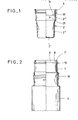
- Fig. 1 den Becher gemäß dem ersten Ausführungsbeispiel in Einzeldarstellung, teils in Ansicht, teils im Schnitt,
- Fig. 2 den Packungshals, ebenfalls teils in Ansicht, teils im Schnitt,
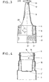
- Fig. 3 die zugehörige Schraubkappe in Einzeldarstellung, teilweise aufgebrochen,
- Fig. 4 den Packungshals im Schnitt, mit zugeordnetem Becher,
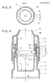
- Fig. 5 eine Unteransicht der Schraubkappe unter Verdeutlichung der ein Hilfsgewinde bildenden Nocken,
- Fig. 6 einen Vertikalschnitt im Bereich des Packungshalses der Zwei-Komponenten-Packung, und zwar in Verkaufsgrundstellung, in gegenüber den voraufgegangenen Figuren vergrößerter Wiedergabe,
- Fig. 7 eine Herausvergrößerung aus Fig. 6, unter besonderer Verdeutlichung der Clipsstufe und Clipsschulter sowie des abdichtenden Wulstes,
- Fig. 8 einen der Fig. 6 entsprechenden Schnitt, jedoch bei abgestemmtem Becherabschnitt,
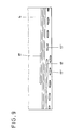
- Fig. 9 eine Abwicklung des Schraubkappengewindes,
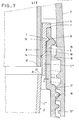
- Fig. 10 den hier allerdings mit der Öffnung nach unten weisenden Becher gemäß dem zweiten Ausführungsbeispiel, ebenfalls teils im Schnitt, teils in Ansicht,
- Fig. 11 die zugehörige, mit dem Becher zu einer hermetisch geschlossenen Kleinpackung bzw. Kapsel verbindbare Schraubkappe, ebenfalls im Halbschnitt und
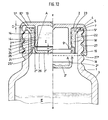
- Fig. 12 Becher und Schraubkappe in bereits zu einer Kapsel verbundenem Zustand, und auf einen Flaschenhals aufgeschraubt (die linke Schnitthälfte zeigt die Situation vor der Freigabe der einen Komponente und die rechtsseitige Hälfte nach Freigabe der einen Komponente durch Abstemmen des bodenseitigen Abschnitts des Bechers).
- 1 the cup according to the first embodiment in individual representation, partly in view, partly in section,
- 2 the pack neck, also partly in view, partly in section,
- 3 the associated screw cap in individual representation, partially broken open,
- 4 the pack neck in section, with an associated cup,
- 5 is a bottom view of the screw cap illustrating the cams forming an auxiliary thread,
- 6 shows a vertical section in the area of the pack neck of the two-component pack, specifically in the basic sales position, in an enlarged representation compared to the previous figures,
- 7 is an enlargement of FIG. 6, with particular clarification of the clip step and clip shoulder and the sealing bead,
- 8 is a section corresponding to FIG. 6, but with the cup section being caulked,
- 9 a development of the screw cap thread,
- 10 the cup with the opening pointing downward according to the second exemplary embodiment, also partly in section, partly in view,
- 11 the associated screw cap which can be connected to the cup to form a hermetically sealed small package or capsule, likewise in half section and
- Fig. 12 Cup and screw cap in a state already connected to a capsule, and screwed onto a bottle neck (the left half of the cut shows the situation before the release of one component and the right half after the release of one component by prying off the bottom section of the cup).
Die Zwei-Komponenten-Packung nimmt in einem in den Packungshals 1 eingelassenen Becher 2 die eine Komponente I und in der volumengrößeren Packung 3 die andere Komponente 11 auf.The two-component pack holds one component I in a
Zum Vermischen beider Komponenten wird der Becher 2 zertrennt. Als Trennwerkzeug dient eine zugleich als Verschluß gestaltete Schraubkappe 4.To mix both components, the
Der aus Kunststoff bestehende Becher 2 bildet in seinem oberen, im wesentlich zylindrisch gestalteten Abschnitt einen auswärts gerichteten Rand 5 aus. Dieser überfängt den korrespondierenden Stirnrand 1' des Packungshalses 1. Der Rand 5 steht nicht nach außen über und definiert die Einhängtiefe des Bechers 2. Letzterer ist aber noch zusätzlich gegen Herausfallen gesichert. Hierzu ist die Becherwand W über eine nahe der Mündung 6 des Packungshalses 1 liegende Clipsstufe St im Packungshals gefesselt. Verwirklicht ist diese Clipsstufe von einer Ringrippe 7 auf der Außenfläche der Bechermantelwand W, welche Ringrippe 7 in eine formentsprechende Ringnut 8 an der Innenfläche des Packungshalses 1 eingreift.The
Die Außenfläche der Bechermantelwand W verläuft unterhalb der Clipsstufe St mit Abstand x zur Innenfläche des Packungshalses 1 (vergl. Fig. 7). Hierdurch läßt sich der Becher 2 bequem einführen. Die dichtende Zuordnung ergibt sich erst im letzten Augenblick der Einsteckzuordnung, wobei zwischen der Ringrippe 7 und der zylindrischen Innenfläche des Packungshalses 1 Reibung auftritt. Durch die Nähe zur Mündung 6 ist diese Zone erhöhter Reibung erheblich verringert; es kommt auch nicht zu einer nennenswerten Komprimierung im Innenraum der Packung bei der Becherzuordnung. Selbst eine geringe Komprimierung wäre nicht in der Lage, den Becher wieder herauszudrücken. Die Clipskräfte sind entsprechend abgestimmt.The outer surface of the cup jacket wall W runs below the clip step St at a distance x from the inner surface of the packing neck 1 (see FIG. 7). This allows the
Der mittels der Schraubkappe 4 zertrennbare Becher 2 bildet eine Sollbruchlinie aus. Letztere ist von einer bechereinwärts liegenden und mit Abstand y vom Becherboden 2" verlaufenden Ringstufe A der Becher- mantelwand W gebildet. Auf letztere trifft die Stoßkante 9' eines in den Becher von oben her einfahrenden Kragens 9 der Schraubkappe 4. Letzterer wurzelt in der Schraubkappendecke 10 und ist als zylindrische Ringwand gestaltet. Die Stoßkante erstreckt sich senkrecht zur Längsmittelachse z-z der rotationssymmetrisch gestalteten Zwei-Komponenten-Packung.The
Nach oben hin setzt sich der Kragen 9 in ein sich zum freien Ende hin kontinuierlich verjüngendes Mündungsrohr 11 fort. Dessen Mündungsöffnung 12 wird von einem angespritzten Stopfen 13 verschlossen gehalten. Es handelt sich um einen Originalitätsverschluß. Die Stoßkante 9' des Kragens 9 fluchtet im wesentlichen mit der Ringstufe A der Bechermantelwand W. Das Abstandsmaß y entspricht etwa 2/3 der Höhe des Bechers 2.The
In der aus Fig. 6 ersichtlichen Verkaufsgrundstellung liegt die Stoßkante 9' des Kragens 9 mit Abstand zur Ringstufe A.In the basic sales position shown in FIG. 6, the abutting edge 9 'of the
Die Mantelfläche des Kragens 9 ist über einen nahe der Kragenstoßkante 9' liegenden Wulst 14 zur Innenfläche der Bechermantelwand hin in der Verkaufsgrundstellung abgedichtet. Der als Ringrippe gestaltete, sich raumparallel zur Stoßkante 9' erstreckende Wulst 14 ist von einer Ringrippe des Bechers 2 gebildet. Der Wulst 14 liegt möglichst in Höhe der Stoßkante 9', so daß auch hier bei Schraubkappenzuordnung erst im letzten Moment die Reibung und Dichtschließung vorliegt, so daß die Schraubkappe 4 nicht vom sich bildenden Innendruck abgestemmt werden kann. Zusätzlich liegt noch eine Sicherungsvorkehrung vor. Letztere besteht darin, daß die Schraubkappe 4 in Verkaufsgrundstellung hinter einer Clipsschulter 15 des Packungshalses 1 verrastet. Die Clipsschulter 15 erstreckt sich etwa auf der gleichen Querschnittsebene wie die Clipsstufe St. Der schulterbildende Wandabschnitt besteht praktisch bzw. anteilig von dem Verdrängungsmaterial der Ringnut 8. Die schraubkappenseitige Gegenschulter 16 ist eine kappeneinwärts gerichtete Ringrippe.The outer surface of the
In der durch die Clipsschulter 15 definierten Verkaufsgrundstellung besteht bereits Gewindeeingriff zwischen der Schraubkappe 4 und dem Packungshals 1. Die Schraubkappe 4 wird einfach aufgeprellt. Dabei tritt der zuunterst liegende Bereich des Schraubgewindes 17 der Kappe 4 in Eingriff mit dem Außengewinde 18 am Packungshals. Das Außengewinde 18 sitzt an einem etwas aufgeweiteten, unteren Abschnitt des Packungshalses 1. Zur erleichterten Zuordnung setzt sich dieser zuunterst liegende Bereich des Gewindes aus einzelnen, in Umfangsrichtung mit Unterbrechung hintereinander liegenden Gewindenocken 17' zusammen. Letztere bilden eine Art Hilfs-oder Vor-Gewinde. Es erstreckt sich über einen Umlaufbereich von 360°. Danach setzt der Vollgewindegang ein. Die einzelnen Gewindenocken 17' sind etwa linsenförmig gestaltet. Die Linsenform bringt sowohl in Drehrichtung der Schraubkappe 4 als auch in Querrichtung derselben (Kappenaufsteckrichtung) konvexe Rundungen. Der Abstand zwischen ihnen entspricht etwa einer Nockenlänge. Insgesamt erstrecken sich über den Umfang 8 Nocken. Sie weisen unterschiedliche Höhe auf, so daß der Übertritt des Außengewindes 18 beim Aufprellen oder Aufschrauben erleichtert ist. Für das Aufschrauben ergibt sich der Vorteil einer verkantungsfreien Zuordnung der Schraubkappe 4.In the basic sales position defined by the
Das Füllen der Zwei-Komponenten-Packung geschieht wie folgt:
- Zunächst wird die volumengrößere Packung 3
mit der Komponente 11 angefüllt. Die Füllhöhe berücksichtigt die Einstecktiefe desBechers 2. Letzterer wird in der erläuterten Weise in den Packungshals eingeführt. Es erfolgt das Füllen desBechers 2 mit der Komponenten I. Anschließend wird die als Verschlußelement und Werkzeug fungierende Schraubkappe 4 aufgebracht. Die Verkaufsgrundstellung ergibt sich aufgrund der Clipsschulter 15, welchevon der Gegenschulter 16 der Schraubkappe überfahren wird. Die mündungsseitige Flanke ist entsprechend abgeschrägt, während die untere Flanke der Clipsschulter 15 wesentlich steiler verläuft. In diesem Stadium befindet sich der zuunterst liegende, von den Gewindenocken 17' gebildete Bereich des Schraubgewindes 17 in Eingriffmit dem Außengewinde 18. Erst durch weiteres Drehen der Schraubkappe 4 in Richtung des Pfeiles 20 (vergl. Fig. 3) nähert sich die Stoßkante 9' des Kragens der Ringstufe A der Bechermantelwand W. DerGewindeeingriff zwischen Schraubkappe 4und dem Packungshals 1 ist von solcher Länge, daß der untere Abschnitt 2"des Bechers 2 beim Weiterschrauben abgetrennt wird, d. h. die filmscharnierartige Materialbrücke 21 zwischen den beiden in radialer Richtung zueinander versetzt liegenden Abschnitten 2"und 2"' der Bechermantelwand W wird zerrissen.Der abgetrennte Becherabschnitt 2" fällt indie Packung 3. Beide Komponenten können nun durch Schütteln vermischt werden. Dabei dient der abgesprengte Becherabschnitt 2" zugleich als Schüttel-Vermischungskörper. Während des Schüttelns bleibt der Dichtschluß zwischendem Kragen 9 und dem nun nur noch ein Dichtungsorgan darstellenden Abschnitt 2111 voll aufrechterhalten.
- First, the
larger volume package 3 is filled withcomponent 11. The filling height takes into account the insertion depth of thecup 2. The latter is introduced into the pack neck in the manner explained. Thecup 2 is filled with the component I. Thescrew cap 4, which acts as a closure element and tool, is then applied. The basic sales position results from theclip shoulder 15, which is run over by thecounter shoulder 16 of the screw cap. The mouth-side flank is correspondingly beveled, while the lower flank of theclip shoulder 15 runs much steeper. At this stage, the lowest area of thescrew thread 17, formed by the thread cams 17 ', is in engagement with theexternal thread 18. Only by further turning thescrew cap 4 in the direction of the arrow 20 (see FIG. 3) does the abuttingedge 9 approach 'of the collar of the ring step A of the cup jacket wall W. The thread engagement between thescrew cap 4 and thepacking neck 1 is of such a length that thelower section 2 "of thecup 2 is separated during further screwing, ie the film hinge-like material bridge 21 between the two in the radial direction to one anotherStaggered sections 2 "and 2"'of the cup jacket wall W are torn. The separatedcup section 2 "falls into thepack 3. Both components can now be mixed by shaking. The blasted-offcup section 2 "also serves as a shaking mixing body. During shaking, the tight seal remains between thecollar 9 and the now only fully maintain a section 2111 representing a sealing member.
Zum Ausgeben der Mischung braucht danach lediglich noch der Stopfen 13 entfernt zu werden.To dispense the mixture, only the
Der Versatz der Wandungsabschnitte 2" und 2"' zueinander entspricht etwas mehr als der Dicke der Bechermantelwand W. Beide Mantelwandabschnitte überlappen einander im Bereich der Materialbrücke 21. Das Maß der Überlappung entspricht etwa einem Fünftel der Dicke der Mantelwand. Unterhalb der Ringstufe A ist der Becher 2 kegelstumpfförmig gestaltet.The offset of the
Die Zwei-Komponenten-Packung gemäß dem zweiten Ausführungsbeispiel ist prinzipiell gleichen Aufbaues; die Bezugsziffern sind, soweit zum Verständnis erforderlich, sinngemäß in die Figuren 10 bis 12 eingetragen. In Weiterbildung weist die Mantelfläche der Becherwand W in Einsteckrichtung des Bechers 2 verlaufende Distanzrippen 22 auf, welche klemmend gegen die Innenwand des Packungshalses 1 treten und so eine gute Drehsicherung bringen. Außerdem versteifen solche Distanzrippen 22 die Becherwand W. Die Rippenbreite entspricht der dazwischenliegenden rippenfreien Zone.The two-component pack according to the second embodiment is basically of the same structure; the reference numerals are, insofar as is necessary for understanding, correspondingly entered in FIGS. 10 to 12. In a further development, the lateral surface of the cup wall W has spacing
Becherrandseitig laufen die Distanzrippen 22 in einen divergierenden, eine kegelstumpfförmige Anlagefläche bildenden Randabschnitt 5' über, welcher dichtend in den Hals 1 eintaucht und zufolge einer nach oben offenen Ringnut 23 besonders elastisch ausfällt. Die Ringnut ist, im Querschnitt gesehen, kerbtalartig gestaltet mit einer schräg nach außen verlaufenden Flanke und einer steilen, d. h. konzentrisch zur Längsmittelachse z-z der rotationssymmetrisch gestalteten Zwei-Komponenten-Packung verlaufenden Flanke.On the cup edge side, the
Die im wesentlichen mit der Ringstufe A der Becherwand W fluchtende Stoßkante 9' erstreckt sich in der in Fig. 12 linksseitig wiedergegebenen Stellung in geringerem Abstand zur Ringstufe A als in Fig. 6, so daß von daher schon eine flachere Kleinpackung erzielt ist.The
Der in den Becher 2 hineinragende Kragen 9 ist gemäß Fig. 12 nun nicht mehr ausschließlich reibungsschlüssig gegen Abzug gesichert. Hierzu bildet die Becherwand W innenseitig mindestens einen ringförmigen Wulst 14 aus. Letzterer erstreckt sich horizontal verlaufend in Nähe der Ringstufe A und ist von einer der Mantelfläche des Kragens 9 angeformten, ringförmigen Klipschulter 24 hintergriffen. Diese in geringem Abstand zum freien Ende des Kragens 9 sitzende Klipsschulter weicht beim Verbinden von Becher und Schraubkappe federelastisch aus. Wie der Zeichnung entnehmbar, sind drei, in Höhenrichtung übereinanderliegende Wülste 14 der Becherwand innenseitig angeformt. Der Abstand zwischen den Wülsten 14 entspricht etwa der doppelten Breite eines Wulstes, welche Wülste außer der axialen Festlegung der eine Kapsel bildenden Teile auch eine gute Abdichtung bringen.The
Zum Befüllen der eine Kleinstmenge an Komponente I aufnehmenden Kapsel wird die Schraubkappe gemäß Fig. 11 auf den Rücken gelegt. Der nach oben weisende Kragen 9 bildet so innenseitig einen napfartigen Füllraum. Anschließend wird der Becher mit nach unten weisender Becheröffnung zugeordnet. Dabei überläuft die Klipsschulter 24 je nach Eindrücktiefe des Bechers nacheinander einen oder mehrere die Einstecktiefe definierende Wülste 14.To fill the capsule holding a small amount of component I, the screw cap according to FIG. 11 is placed on the back. The upwardly facing
Um bei dieser Montage jedwede Beeinträchtigung vom bodenseitigen, über die Sollbruchlinie mit dem oberen Abschnitt 2"' des Bechers verbundenen Abschnitt 2" fernzuhalten, setzt sich die Becherwand W, benachbart zum becherbodenseitigen Abschnitt 2", in eine Stützwand 25 fort. Es handelt sich hier praktisch um einen im Querschnitt etwas reduzierten Becherwandfortsatz. Die Stützwand entspringt dem Bereich der Sollbruchstelle und ist bis auf Höhe der Becherboden-Unterseite 26 vorgezogen. Die Stirnfläche 25' kann diese Becherboden-Unterseite 26 sogar noch geringfügig überragen. Ein plan aufsetzendes Prellwerkzeug kommt so selbst bei geringfügiger axialer Stauchung der Mantelwand nicht bis an die Becherboden-Unterseite 26. Außer dem von der Stützwand 25 gebildeten Schutzwall kann auch noch eine weitere schützende Abdeckung genutzt werden, nämlich die im wesentlichen zylindrisch gestaltete Topfwandung 27 der Schraubkappe 4, indem die Stirnfläche 25' der Stützwand 25 in fluchtende, d. h. ebenengleiche Ausrichtung zur Stirnwand 27' der Kappenwand 27 gebracht wird. Bei dieser vollen Ineinandertauchlage bleibt der geringe Ringspalt zwischen Stoßkante 9' des Kragens 9 erhalten. Außerdem verbleibt ein Abstand D zwischen der Oberseite 5" des Kragens 9 und der korrespondierenden Innenfläche 10' der Schraubkappen-Decke 10.In order to keep away any impairment from the bottom-
Die Distanzrippen 22 schließen höhengleich mit der Stirnfläche 25' ab, so daß die Auflagefläche noch durch die Stirnenden der Distanzrippen vergrößert ist.The
Zur Ingebrauchnahme wird auch hier unter Gewindeeingriff 16/18 von Schraubkappe 4 und Flaschenhals 1 die Kapsel der volumengrößeren, bspw. Wasser enthaltenden Packung 3 zugeordnet. Dabei ergibt sich eine Grundstellung, wie sie aus der linken Hälfte der Fig. 12 hervorgeht, in der also die Komponenten 1 und 11 noch getrennt sind. Erst durch weiteres Drehen der Schraubkappe 4 nähert sich die Stoßkante 9' des Kragens der Ringstufe A der Becherwand W. Der Gewindeeingriff zwischen Schraubkappe 4 und dem Packungshals ist von solcher Länge, daß der untere Abschnitt 2" des Bechers 2 beim Weiterschrauben abgetrennt wird, wohingegen der obere Abschnitt 2"' im Flaschenhals verbleibt. Dabei wird die filmscharnierartige Materialbrücke 21 zwischen den beiden in radialer Richtung zueinander versetzt liegenden Abschnitten 2" und 2"' der Becherwand W zerrissen. Der abgetrennte Becherabschnitt 2" fällt in die Packung 3. Beide Komponenten können nun durch Schütteln gut vermischt werden. Dabei dient der abgesprengte Behälterabschnitt 2" zugleich als Schüttel-Mischkörper. Während des Schüttelns bleibt der Dichtschluß zwischen dem Kragen und der Becherwand aufrechterhalten.For use, the capsule of the larger-volume, for example water-containing
Nach Entfernen der Schraubkappe 4 kann die vermischte Substanz ausgegeben werden.After removing the
Alle in der Beschreibung erwähnten und in der Zeichnung dargestellten neuen Merkmale sind erfindungswesentlich, auch soweit sie in den Ansprüchen nicht ausdrücklich beansprucht sind.All the new features mentioned in the description and shown in the drawing are essential to the invention, even if they are not expressly claimed in the claims.
Claims (15)
Priority Applications (1)
| Application Number | Priority Date | Filing Date | Title |
|---|---|---|---|
| AT84108855T ATE25225T1 (en) | 1983-07-30 | 1984-07-26 | TWO COMPONENT PACK. |
Applications Claiming Priority (4)
| Application Number | Priority Date | Filing Date | Title |
|---|---|---|---|
| DE3327615 | 1983-07-30 | ||
| DE3327615A DE3327615C2 (en) | 1983-07-30 | 1983-07-30 | Two-component pack |
| DE3426739 | 1984-07-20 | ||
| DE19843426739 DE3426739A1 (en) | 1984-07-20 | 1984-07-20 | TWO-COMPONENT PACK |
Publications (3)
| Publication Number | Publication Date |
|---|---|
| EP0133293A2 true EP0133293A2 (en) | 1985-02-20 |
| EP0133293A3 EP0133293A3 (en) | 1986-01-15 |
| EP0133293B1 EP0133293B1 (en) | 1987-01-28 |
Family
ID=25812773
Family Applications (1)
| Application Number | Title | Priority Date | Filing Date |
|---|---|---|---|
| EP84108855A Expired EP0133293B1 (en) | 1983-07-30 | 1984-07-26 | Two-component package |
Country Status (2)
| Country | Link |
|---|---|
| EP (1) | EP0133293B1 (en) |
| DE (1) | DE3462237D1 (en) |
Cited By (11)
| Publication number | Priority date | Publication date | Assignee | Title |
|---|---|---|---|---|
| FR2568547A1 (en) * | 1984-08-04 | 1986-02-07 | Celamerck Gmbh & Co Kg | DEVICE FOR MIXING AND SPRAYING CONCENTRATED SUBSTANCES AND USE THEREOF |
| EP0237889A3 (en) * | 1986-03-13 | 1988-09-21 | Robert Finke Kommanditgesellschaft | Two-component package |
| FR2623477A1 (en) * | 1987-11-20 | 1989-05-26 | Sah Participations Proced Indl | Stopper containing a tub of absorbent material fixed permanently to the stopper |
| WO1991017930A3 (en) * | 1990-05-21 | 1992-01-09 | Finke Robert Gmbh | Multicomponent package |
| FR2736038A1 (en) * | 1995-06-28 | 1997-01-03 | Inibsa Lab | BOTTLE FOR TWO PRODUCTS |
| EP0921079A1 (en) | 1997-12-02 | 1999-06-09 | Plastikwerk Expan GesmbH | Two compartment container |
| EP0943552A1 (en) * | 1998-03-20 | 1999-09-22 | Wella Aktiengesellschaft | Container for packaging first and second materials maintained separate prior to use in admixture |
| WO2001076977A1 (en) * | 2000-04-12 | 2001-10-18 | Emvi Limited | Container for mixing two components |
| AT410085B (en) * | 1997-12-02 | 2003-01-27 | Feichtinger Ernst Expan | Container for separated fluids |
| WO2006004345A1 (en) * | 2004-07-01 | 2006-01-12 | Hyo Bin Im | Cover assembly enable to mix interior material at opening |
| FR2916187A1 (en) * | 2007-05-14 | 2008-11-21 | Marguerite Deperrois | CAP FOR CONTAINER FORMING ADDITIVE TANK |
Family Cites Families (5)
| Publication number | Priority date | Publication date | Assignee | Title |
|---|---|---|---|---|
| GB1083335A (en) * | 1963-05-28 | 1967-09-13 | Calmic Ltd | Storing, mixing and dispensing devices,e.g. for antibiotics |
| US3458076A (en) * | 1968-06-26 | 1969-07-29 | Owens Illinois Inc | Two-compartment package |
| FR2169445A6 (en) * | 1971-03-15 | 1973-09-07 | Oreal | |
| FR2153767A5 (en) * | 1971-09-23 | 1973-05-04 | Gallia Sa Eugene | |
| FR2370650A1 (en) * | 1976-11-15 | 1978-06-09 | Oreal | PACKAGING AND DISTRIBUTION CONTAINER CONTAINING TWO SEPARATE COMPARTMENTS IN STORAGE |
-
1984
- 1984-07-26 DE DE8484108855T patent/DE3462237D1/en not_active Expired
- 1984-07-26 EP EP84108855A patent/EP0133293B1/en not_active Expired
Cited By (18)
| Publication number | Priority date | Publication date | Assignee | Title |
|---|---|---|---|---|
| FR2568547A1 (en) * | 1984-08-04 | 1986-02-07 | Celamerck Gmbh & Co Kg | DEVICE FOR MIXING AND SPRAYING CONCENTRATED SUBSTANCES AND USE THEREOF |
| EP0170980A3 (en) * | 1984-08-04 | 1987-11-11 | Celamerck Gmbh & Co. Kg | Mixing and spraying device |
| EP0237889A3 (en) * | 1986-03-13 | 1988-09-21 | Robert Finke Kommanditgesellschaft | Two-component package |
| FR2623477A1 (en) * | 1987-11-20 | 1989-05-26 | Sah Participations Proced Indl | Stopper containing a tub of absorbent material fixed permanently to the stopper |
| WO1991017930A3 (en) * | 1990-05-21 | 1992-01-09 | Finke Robert Gmbh | Multicomponent package |
| EP0462390A3 (en) * | 1990-05-21 | 1992-05-13 | Robert Finke Gmbh & Co. Kg | Multicomponent package |
| US5353928A (en) * | 1990-05-21 | 1994-10-11 | Robert Finke Gmbh & Co. Kg | Multicomponent package |
| BE1010542A5 (en) * | 1995-06-28 | 1998-10-06 | Inibsa Lab | New bottle for two products. |
| FR2736038A1 (en) * | 1995-06-28 | 1997-01-03 | Inibsa Lab | BOTTLE FOR TWO PRODUCTS |
| EP0921079A1 (en) | 1997-12-02 | 1999-06-09 | Plastikwerk Expan GesmbH | Two compartment container |
| US6073803A (en) * | 1997-12-02 | 2000-06-13 | Plastikwerk Expan Gmbh | Container |
| AT410085B (en) * | 1997-12-02 | 2003-01-27 | Feichtinger Ernst Expan | Container for separated fluids |
| EP0943552A1 (en) * | 1998-03-20 | 1999-09-22 | Wella Aktiengesellschaft | Container for packaging first and second materials maintained separate prior to use in admixture |
| WO2001076977A1 (en) * | 2000-04-12 | 2001-10-18 | Emvi Limited | Container for mixing two components |
| WO2006004345A1 (en) * | 2004-07-01 | 2006-01-12 | Hyo Bin Im | Cover assembly enable to mix interior material at opening |
| US7578386B2 (en) | 2004-07-01 | 2009-08-25 | Hyo Bin Im | Cover assembly enable to mix interior material at opening |
| FR2916187A1 (en) * | 2007-05-14 | 2008-11-21 | Marguerite Deperrois | CAP FOR CONTAINER FORMING ADDITIVE TANK |
| WO2008152219A1 (en) * | 2007-05-14 | 2008-12-18 | Marguerite Deperrois | Cap for receptacle forming an additive reservoir |
Also Published As
| Publication number | Publication date |
|---|---|
| EP0133293B1 (en) | 1987-01-28 |
| DE3462237D1 (en) | 1987-03-05 |
| EP0133293A3 (en) | 1986-01-15 |
Similar Documents
| Publication | Publication Date | Title |
|---|---|---|
| DE3327615C2 (en) | Two-component pack | |
| DE2753737C2 (en) | Container for two loose materials | |
| DE60216215T2 (en) | Child safety lock and packaging | |
| DE2529340C3 (en) | Container with a screw cap and method of putting the screw cap on | |
| DE69303434T2 (en) | Containers for pharmaceutical products from two separate components, with means for mixing and dispensing them | |
| EP0235806B1 (en) | Bottle sealing cap for two component containers | |
| EP0520207A1 (en) | Bottle closure for two-compartment containers | |
| DE8814309U1 (en) | Mixing device | |
| DE19812657A1 (en) | Two-component container for the temporary storage of peroxide and hair dye | |
| EP0133293B1 (en) | Two-component package | |
| WO1990003924A1 (en) | Screw top | |
| DE69404505T2 (en) | Outlet closure | |
| EP0243730A2 (en) | Bottle with two compartments | |
| AT394536B (en) | TWO-PIECE CAP WITH SCREW THREAD | |
| DE8606940U1 (en) | Two-component pack | |
| DE19807768A1 (en) | Closure for bucket or tub-shaped plastic container has inwards directed | |
| DE3517072A1 (en) | DOSING DEVICE FOR LIQUIDS | |
| DE2625175C3 (en) | Container closure with active ingredient chamber | |
| WO1998045189A1 (en) | Plastic soldered pouring spout part | |
| EP0184742B1 (en) | Dispenser for the dosed delivery of tablets, pastes or the like | |
| DE3437574C2 (en) | ||
| DE69603290T2 (en) | TWO-PIECE DISPENSER CAP WITH WARRANTY LOCK | |
| EP1465814A2 (en) | Closing device for a container | |
| WO2003093115A2 (en) | Sealing cap for bottles | |
| DE9403102U1 (en) | Childproof screw cap with integrated refill opening |
Legal Events
| Date | Code | Title | Description |
|---|---|---|---|
| PUAI | Public reference made under article 153(3) epc to a published international application that has entered the european phase |
Free format text: ORIGINAL CODE: 0009012 |
|
| AK | Designated contracting states |
Designated state(s): AT BE CH DE FR GB LI LU NL |
|
| PUAL | Search report despatched |
Free format text: ORIGINAL CODE: 0009013 |
|
| AK | Designated contracting states |
Designated state(s): AT BE CH DE FR GB LI LU NL |
|
| 17P | Request for examination filed |
Effective date: 19851231 |
|
| 17Q | First examination report despatched |
Effective date: 19860715 |
|
| GRAA | (expected) grant |
Free format text: ORIGINAL CODE: 0009210 |
|
| AK | Designated contracting states |
Kind code of ref document: B1 Designated state(s): AT BE CH DE FR GB LI LU NL |
|
| REF | Corresponds to: |
Ref document number: 25225 Country of ref document: AT Date of ref document: 19870215 Kind code of ref document: T |
|
| REF | Corresponds to: |
Ref document number: 3462237 Country of ref document: DE Date of ref document: 19870305 |
|
| ET | Fr: translation filed | ||
| PLBI | Opposition filed |
Free format text: ORIGINAL CODE: 0009260 |
|
| 26 | Opposition filed |
Opponent name: L' OREAL Effective date: 19871008 |
|
| NLR1 | Nl: opposition has been filed with the epo |
Opponent name: L' OREAL |
|
| PLBN | Opposition rejected |
Free format text: ORIGINAL CODE: 0009273 |
|
| STAA | Information on the status of an ep patent application or granted ep patent |
Free format text: STATUS: OPPOSITION REJECTED |
|
| 27O | Opposition rejected |
Effective date: 19881021 |
|
| NLR2 | Nl: decision of opposition | ||
| EPTA | Lu: last paid annual fee | ||
| PGFP | Annual fee paid to national office [announced via postgrant information from national office to epo] |
Ref country code: CH Payment date: 20000104 Year of fee payment: 16 |
|
| PGFP | Annual fee paid to national office [announced via postgrant information from national office to epo] |
Ref country code: AT Payment date: 20000113 Year of fee payment: 16 |
|
| PGFP | Annual fee paid to national office [announced via postgrant information from national office to epo] |
Ref country code: NL Payment date: 20000117 Year of fee payment: 16 |
|
| PGFP | Annual fee paid to national office [announced via postgrant information from national office to epo] |
Ref country code: LU Payment date: 20000120 Year of fee payment: 16 |
|
| PGFP | Annual fee paid to national office [announced via postgrant information from national office to epo] |
Ref country code: BE Payment date: 20000208 Year of fee payment: 16 |
|
| PG25 | Lapsed in a contracting state [announced via postgrant information from national office to epo] |
Ref country code: LU Free format text: LAPSE BECAUSE OF NON-PAYMENT OF DUE FEES Effective date: 20000726 Ref country code: AT Free format text: LAPSE BECAUSE OF NON-PAYMENT OF DUE FEES Effective date: 20000726 |
|
| PG25 | Lapsed in a contracting state [announced via postgrant information from national office to epo] |
Ref country code: LI Free format text: LAPSE BECAUSE OF NON-PAYMENT OF DUE FEES Effective date: 20000731 Ref country code: CH Free format text: LAPSE BECAUSE OF NON-PAYMENT OF DUE FEES Effective date: 20000731 Ref country code: BE Free format text: LAPSE BECAUSE OF NON-PAYMENT OF DUE FEES Effective date: 20000731 |
|
| BERE | Be: lapsed |
Owner name: ROBERT FINKE K.G. Effective date: 20000731 |
|
| PG25 | Lapsed in a contracting state [announced via postgrant information from national office to epo] |
Ref country code: NL Free format text: LAPSE BECAUSE OF NON-PAYMENT OF DUE FEES Effective date: 20010201 |
|
| REG | Reference to a national code |
Ref country code: CH Ref legal event code: PL |
|
| NLV4 | Nl: lapsed or anulled due to non-payment of the annual fee |
Effective date: 20010201 |
|
| REG | Reference to a national code |
Ref country code: GB Ref legal event code: IF02 |
|
| PGFP | Annual fee paid to national office [announced via postgrant information from national office to epo] |
Ref country code: FR Payment date: 20030609 Year of fee payment: 20 |
|
| PGFP | Annual fee paid to national office [announced via postgrant information from national office to epo] |
Ref country code: GB Payment date: 20030612 Year of fee payment: 20 |
|
| PGFP | Annual fee paid to national office [announced via postgrant information from national office to epo] |
Ref country code: DE Payment date: 20030625 Year of fee payment: 20 |
|
| PG25 | Lapsed in a contracting state [announced via postgrant information from national office to epo] |
Ref country code: GB Free format text: LAPSE BECAUSE OF EXPIRATION OF PROTECTION Effective date: 20040725 |
|
| REG | Reference to a national code |
Ref country code: GB Ref legal event code: PE20 |