EP0133286A1 - Film processing machine - Google Patents
Film processing machine Download PDFInfo
- Publication number
- EP0133286A1 EP0133286A1 EP84108770A EP84108770A EP0133286A1 EP 0133286 A1 EP0133286 A1 EP 0133286A1 EP 84108770 A EP84108770 A EP 84108770A EP 84108770 A EP84108770 A EP 84108770A EP 0133286 A1 EP0133286 A1 EP 0133286A1
- Authority
- EP
- European Patent Office
- Prior art keywords
- bags
- stacking
- bag
- stack
- bar
- Prior art date
- Legal status (The legal status is an assumption and is not a legal conclusion. Google has not performed a legal analysis and makes no representation as to the accuracy of the status listed.)
- Granted
Links
Images


Classifications
-
- B—PERFORMING OPERATIONS; TRANSPORTING
- B31—MAKING ARTICLES OF PAPER, CARDBOARD OR MATERIAL WORKED IN A MANNER ANALOGOUS TO PAPER; WORKING PAPER, CARDBOARD OR MATERIAL WORKED IN A MANNER ANALOGOUS TO PAPER
- B31B—MAKING CONTAINERS OF PAPER, CARDBOARD OR MATERIAL WORKED IN A MANNER ANALOGOUS TO PAPER
- B31B70/00—Making flexible containers, e.g. envelopes or bags
- B31B70/74—Auxiliary operations
- B31B70/92—Delivering
- B31B70/98—Delivering in stacks or bundles
- B31B70/984—Stacking bags on wicket pins
-
- B—PERFORMING OPERATIONS; TRANSPORTING
- B31—MAKING ARTICLES OF PAPER, CARDBOARD OR MATERIAL WORKED IN A MANNER ANALOGOUS TO PAPER; WORKING PAPER, CARDBOARD OR MATERIAL WORKED IN A MANNER ANALOGOUS TO PAPER
- B31B—MAKING CONTAINERS OF PAPER, CARDBOARD OR MATERIAL WORKED IN A MANNER ANALOGOUS TO PAPER
- B31B2155/00—Flexible containers made from webs
- B31B2155/003—Flexible containers made from webs starting from tubular webs
-
- B—PERFORMING OPERATIONS; TRANSPORTING
- B31—MAKING ARTICLES OF PAPER, CARDBOARD OR MATERIAL WORKED IN A MANNER ANALOGOUS TO PAPER; WORKING PAPER, CARDBOARD OR MATERIAL WORKED IN A MANNER ANALOGOUS TO PAPER
- B31B—MAKING CONTAINERS OF PAPER, CARDBOARD OR MATERIAL WORKED IN A MANNER ANALOGOUS TO PAPER
- B31B2160/00—Shape of flexible containers
- B31B2160/10—Shape of flexible containers rectangular and flat, i.e. without structural provision for thickness of contents
Definitions
- the invention relates to a film processing machine for producing, stacking and depositing flat packaging made of thermoplastic plastic film, such as bags or sacks, with a separating and welding device working in a horizontal plane for processing the double-layered film webs fed there vertically and one directly to the separating and welding device connected stacking device, preferably provided with stacking pins, in which the packs are held hanging, and with a connected conveying device on which the packs are deposited and, if necessary, punched out by a punching device and then transported away.
- a film processing machine for producing, stacking and depositing flat packaging made of thermoplastic plastic film, such as bags or sacks, with a separating and welding device working in a horizontal plane for processing the double-layered film webs fed there vertically and one directly to the separating and welding device connected stacking device, preferably provided with stacking pins, in which the packs are held hanging, and with a connected conveying device on which the packs are deposited and, if necessary, punched out by a punching device and then transported away
- Foil processing machines must be suitable to produce bags or sacks of different designs. These are not only to be understood as different sizes, but also the different types of bags or sacks, for example whether they are are bags or sacks that deal with a bottom seam, ie a transverse weld seam with an adjacent separating cut or a side seam, ie two weld seams running parallel and at a distance from one another, between which a separating cut is made. Such welds are also often referred to as double bottom seams.
- bag making machines should also be able to process films with a wide variety of properties, such as films made from different film materials and different film thicknesses.
- foils can be welded well, but are difficult to grasp and, accordingly, difficult to transport as film webs or as finished bags in the processing machine. Thick foils need a longer welding time, with thin foils the welding time is usually short. However, due to their high flexibility, these are very difficult to process, especially difficult to transport as finished bags.
- the bags are produced in a bag manufacturing machine not only from the double-layer film web, usually a half tube or tube, by cross-welding and cross-cutting, but also stacked within the bag manufacturing machine and, if they are stacked, are optionally fed as a batch for further processing, for example by attachment of die cuts, it is very desirable to safely guide the individual bags or a stack of bags from one processing station to the next processing station. If at today's high processing speeds, For example, a cycle rate of 100 to 200 bags per minute, a bag slipped from the transport devices or is not properly detected, this leads to such difficulties and disturbances that in many cases the entire film processing machine must be shut down to remedy the situation.
- the present invention is based on the object of providing such a film processing machine in which the bags or stack of bags are reliably detected in the stations of manufacture, stacking and storage, regardless of their dimensioning and their film material and properties of the film.
- the task is also assumed, despite the high number of cycles in the production of bags or sacks, to prevent the bags or sacks from baking when they are stacked due to weld seams which have not yet cooled sufficiently, and to provide a device for stacking and further processing a bag or a block of bags which in conjunction with, but also without pens, enables stacking and allows sufficient and safe further processing of the bags after their manufacture.
- a film processing machine for producing, stacking and depositing flat packaging made of thermoplastic plastic film, such as bags or sacks has a separating and welding device working in a horizontal plane for processing the double-layered film webs fed vertically there and one directly to the separator - And welding device connected, preferably provided with stacking pins, in which the packages are held hanging and with a connected conveyor, on which the packages are deposited and optionally punched out by a punching device and then transported away, proposed according to the invention that in the area between the Stacking device and the conveyor a reciprocating gripping device is arranged, which grips the stack of objects and transported to the conveyor and rests thereon.
- the proposal according to the invention to take the stack of bags immediately after the manufacture as a stack of bags with a gripping device and to transport them to a conveyor and place them on the conveyor means that the bags are always held together and no single bag is lost or lost can detach or move from the other.
- the proposal to use a reciprocating gripper between the storage of the bags or the stacking device in direct connection with the manufacture, which gripper the stacked bags grasped and transported in a coherent manner to a filing system allows various modifications. So the reciprocating gripping device can be designed so that it grips a stack of bags on both sides on the vertical side edges.
- the further solution according to the invention is particularly advantageous in that the gripping device is designed as a bar and extends in the horizontal plane over the substantial width of the film processing machine.
- a gripping device can grasp a plurality of stacks of bags arranged side by side.
- This solution also includes that the gripping device is not matched to the width of the individual bags produced or need to be graduated, because regardless of the width of the individual bags or the number of bags lined up next to one another, their detection is ensured.
- the gripper bar is assigned an existing counter bar on the other side of the bag stack, which also extends over the essential width of the bag manufacturing machine and with the gripper bar for the purpose of clamping the bag stack or bags to it Gripper bar interacts.
- a particularly advantageous solution consists in the fact that the gripper bar has an upper bar part and a lower bar part which, like a pair of pliers, have a horizontal axis of rotation or an associated one horizontal axis of rotation are pivotable.
- the cooperating counter bar is then particularly advantageously designed in such a way that a sword engages between the upper bar part and the lower bar part when the stack of bags in between is folded, which in a further embodiment of the invention extends in a horizontal plane over the essential width of the machine and on Machine frame is arranged stationary.
- the sword thus serves to insert the bags of the stack into the pliers of the gripper bar. Since the gripper bar is moved back and forth, the sword is stationary according to a particularly advantageous solution.
- the movement of the reciprocating gripper bar can be done in different ways.
- the two ends of the bar can be arranged on respectively assigned chains, which enable the gripper bar to be moved back and forth by changing the direction of rotation.
- the reciprocating gripper bar can be arranged at its two ends at the front ends of associated piston rods of pneumatic cylinders.
- the tongs can also be opened in order to release the stack of bags, for example by means of link guides attached to the machine frame.
- a reciprocating clamping strip extending over its substantial width, which clamps the stack of objects placed on the conveyor by the gripper device on the conveyor. This clamping then results in the bags of the stack being released from the gripper bar when the gripper bar moves further, so that the final storage can take place on the storage table designed as a conveyor.
- the aforementioned clamping of the stack of bags on the conveyor also ensures the predeterminable exact location, so that the punch comes into effect at a predetermined position on the stack of bags.
- the rotating precipitate consists of a hollow tube on which a bent sheet metal strip extending over the length of the tube is arranged , In the hollow tube and in the sheet metal strip extending over their length there are suction openings and on the outer edge of the sheet metal strip at intervals which correspond to the spacing of the stacking pins of the stacking device, open recesses are present.
- the measures described above thus lead to the working method according to the invention that the individual bags before they leave the separating and the welding device is held by the suction on the rotating precipitator and is opened by the latter on the pins and this holder on the pins frees the pouch from the precipitate, after the stacking of a predetermined number of bags the gripping device detects the stack of bags and then the stack of pins withdrawing them, release the stack of bags and, after transporting the stack of bags onto the conveyor, the pressure bar holds the stack of bags on the conveyor and only then does the gripping device release the stack of bags.
- bags are produced at a cycle rate of 100 bags per minute, the bags are stacked at a rate of only 50 bags per minute because there are a total of two stacking devices. Therefore, based on a stacking device, the time from depositing the previous bag to the next bag is sufficiently long that the welds have had an opportunity to cool down.
- the racket consists of a bar which extends over the width or substantial width of the bag-making machine and is mounted to swing back and forth about a horizontal axis, the bearing axes having a short length only being present in the region of their attachment to the side walls of the machine.
- the strip going to the right is provided with blow-out openings on both sides facing the rows of pins.
- the back and forth movement of the racket can be done by a pneumatic rotary piston motor.
- the solution is particularly advantageous that piston rods of pneumatic cylinders are arranged on both sides of the arms carrying the blow bar, in which case the cylinders are then pivotally mounted about horizontal axes in a further embodiment according to the invention.
- the stacking device has a horizontal working surface with which the bags or the pile of bags are further processed in connection with tools .
- the solution according to the invention in connection with the manufacture of the bags in an area below the separating welding device in connection with the stacking device, at the same time providing work surfaces which form the basis for the further processing of a bag or a bag block, has many advantages yourself. So there is no further movement for further processing of a bag or stack of bags. This enables exact positioning of the machining operations to be carried out with little effort.
- the processing tools can work in time with the bag production, so that simplification also takes place in this regard.
- the holding device of the upper horizontal work surface can have different forms of training with different movements.
- the holding device is provided with a support surface for the edge of the bag to be stacked, the weld seam of the bag to be stacked is prevented from baking on the previous bag of the stack.
- the tools which each process a single bag, can perform the holding function, advantageously in an alternating rhythm between a welding bar.
- the processing tool can thus be a welding bar, which connects the bags of the block in a known manner in such a way that, with the stacking of the bags, each bag fed to the stack is connected to the preceding bag by welding. This avoids stacking pins, which could, however, also be retained.
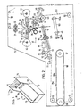
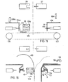
- the film processing machine 10 has the welding and stacking device 11 with the side walls 12 and 13 of greater height and the storage table 15 with the side walls 16 and 17 of lower height.
- the part for producing the bags and stacking them can represent a structural unit with the storage table 15.
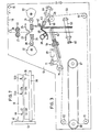
- FIGS. 2 to b The elements shown in the following FIGS. 2 to b are mounted in the side walls 13 and 14 or 15 and 17, FIGS. 2 to 6 only show the storage in the walls 13 and 15 in the drawing.
- the double-layer film 19 to be processed is fed to the pair of preferred rollers 21, 22 via a first deflection roller 20 and a second deflection roller 20a fed. It passes between the blow comb tubes 23 and 24 to the separating welding device 25, consisting of the welding bars 26 and 27, which bear against the cams 32 and 33 via associated webs 28, 29 with rollers 30, 31, which are connected via corresponding drive shafts 34 and 35 are driven.
- the welding bar 27 is provided with a knife 36.
- the welding bar 26 has a corresponding longitudinal recess. It should be noted that the separation welder is known. It can be replaced by another cutting and welding device.
- Blower nozzles 40 extending from the hollow tube 38 are provided. These can be in the form of a longitudinal slot. The holes can also be drilled one after the other in a row or in two rows.
- the needle strip 43 Arranged behind the strip 41 is the needle strip 43, which has needles 44 forward in the direction of the precipitation and, as FIG. 7 shows, a plurality of needles 44a and 44b at intervals.
- the needle bar is fastened at both ends to the piston rod 45 of a pneumatic cylinder 46, which is fastened to the wall 13 via connecting elements. As a result, the needle bar is retractable, as will be described later.
- the strip 41 has open recesses 47, 47a downward in the region of the needles 44, while the sheet 39 has opposite recesses 48, 48a open to the outside.
- Sprockets 49, 50, 51 and 52 are mounted in the side walls 13, 16 and carry a chain 53.
- the chain wheels 49 and 52 are provided with disengageable drives.
- a mirror-image arrangement is present on the side parts 14 and 17.
- the chain 53 carries, as can also be seen from FIG. 9, a gripper bar 54 which consists of the upper bar 54a and the lower bar 54b. which are movable like pliers.
- the lower bar consists of a cross member 55, which carries a piston-cylinder arrangement 56 at both ends, so that the bar 54b can be displaced in the indicated double arrow direction via the piston rod.
- the upper bar consists of individual sections. These can be raised and lowered about the axis 57 via a piston-cylinder arrangement 58.
- a tension spring ensures the open position as the starting position.
- the bars have opposite and spaced rows of bumps 59 on the inner surfaces facing one another. Between these bumps with flat obliquely tapering wedge surfaces, a sword designed in the form of a sheet metal engages 59, which extends between the side cheeks 13 and 14 and is fastened to the side cheek 13 via a flange 60. According to the representation in FIG. 10, this sword has recesses 61, 61a which are spaced apart and which are dimensioned and arranged at such a distance that the aforementioned bumps of the gripper bar can engage between them.
- the gripper bar 54 is guided on the side wall 13 within a rail 62.
- a further pneumatic cylinder 69 is fastened to the frame 13, the piston rod 70 of which is mounted on the one leg 71 of an angle lever 72 which can be pivoted about the axis 73 and which carries the chain wheel 75 at its front lower end of the leg 74.
- the gripper bar is moved via the chain 53 by the drive of the chain wheel 49 in the direction of the bag stack, to the extent that the sword 59 between the bars 54a and 54b engages and the foil layers of the stack open the pliers.
- the stack of bags is thus folded.
- the tongs move out of the area of the sword, with the result that the tongs close under the action of the tension spring 47 and hold the bags of the stack.
- the gripper bar is driven so far over the belt 66 by the drive of the chain wheel 52 that the lower end of the "pile of tunnels is still in the region of the deflection roller 67 is present. There, the lower end of the stack of bags is clamped by the clamping bar 65 of the pneumatic cylinder 63 with the result that the bag block is pulled out of the pliers when the gripper bar 54 is moved further and is thus placed on the upper run 66a of the belt, in the direction indicated by the arrow 77 is movable in batches. If bag stacks of only a short length are deposited, then the gripper bar 54 should have a smaller height distance from the upper run 66a of the belt.
- the sprocket 75 is moved downward in the specified direction of rotation 77a via the pneumatic cylinder 69 and the piston rod 70 and the lever 72, so that the gripper bar has a smaller height distance from the tray.
- Corresponding elements that balance the chain length are available.
- FIG. 6 shows that the gripper bar 54 has already been moved back into its waiting position in order to soon pick up the next bag.
- the clamping bar 65 still clamps the stack of bags on the roller 67, the stack of bags being punched by a punching knife 78, driven by the piston rod 79 of the pneumatic cylinder 80.
- the design of the gripper bar which extends over the width of the machine and which cooperates with the counterbars on the other side of the stack of bags, particularly advantageously in the form of a sword, which is mounted in a stationary manner, enables the stack of bags to be detected independently of the width of the stack of bags. It is thus understandable that two or more stacks of bags can also be transported side by side at the same time, because the solution according to the invention shows no restriction here.
- Fig. 11 shows that the gripper bar in connection with the counter bar on the other side of the bag, advantageously in the form of the fixed sword, can also grasp and transport away two opposite stacks of bags, because the solution according to the invention is not subject to any restrictions in this regard either .
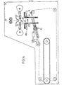
- Fig. 11 shows that below the separating welding device there are two stacking trays, so that the stacking tray 41a, 42a with the needle bar 43a and its drive through the cylinder 46a are added in mirror image to the previously described stacking tray.
- the work is done shows that the first bag is opened on the first stacking device 41a, the second bag on the second stacking device 41, the third bag in turn on the first stacking device 41 and so on, by means of a racket 81 which, as shown in the figures 12 and 13 has a strip 82 which extends over the width of the film processing machine and is supported at both ends on an arm 83 which is pivotably mounted to and fro on the side wall 13 on a pivot 84 in the arrow direction 85 indicated.
- reference numerals 41 and 41a denote the strips between which open-down recesses 47 pass through the needles 44.
- the separating welding device has two welding devices 86, 86a and 87, 87a located one behind the other at a distance, then it is possible for the bag or sack to be stacked in the Area of the stacking device has a heated weld.
- the weld seams are sufficiently cooled due to the slow processing time here, in particular if the air-blowing tubes 23 and 24 are present as shown in FIG. 2. In order to achieve a higher cycle rate, it is suggested
- the bat is provided in the region below the welding device with a blow-out opening 88 and 89 assigned to each side. If the racket is moved to the left in the direction of the rest 41a, then the outlets 88 blow. If it is moved to the right in the direction of the rest 41, then the outlets 89 blow, which extend over the entire length of the blow bar. They can consist of a continuous slot, but can also consist of individual holes located close together.
- the arms 83 shown in FIG. 13, the arm 83, via pivot joints 90 and 91, piston rods 92 and 93 of pneumatic cylinders 94 and 95 are arranged, which are assigned holders 96 and 97 on rotary axes 98 and 99 are pivotable.
- Fig. 13 also shows the sword 59 in connection with the pliers from the beam parts 54a and 54b. 13 are attached to a piston rod 100 because the chain drive shown in the drawings, which carries the gripper bar, can also be replaced by a pneumatic drive.
- FIG. 14 shows the solution modified compared to FIG. 11 with the proviso that a racket 101 is used which is moved back and forth in the horizontal plane in accordance with the double arrow direction 102.
- Pins 44 and 44a are present on associated, opposite piston rods of cylinders 46 and 46a.
- the stacking device 41 and 41a is present below the separating and welding device 26 and 27, with the vertical regions 103 and 103a and horizontal regions 104 and 104a.
- the racket 101 is fastened on its underside or on its top to a conveyor belt 105 which is moved back and forth over deflection rollers 106 and 107, so that the bags are stacked alternately on the stacking device 41 and 41a in succession.
- the horizontal stacking surfaces 104 and 104a are assigned tools 108 and 108a, respectively, which perform perforations, punchings, perforations or advantageously welds. However, it can only be on holding devices, the mode of operation of which is described in connection with FIG. 16.
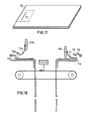
- FIG. 16 shows the movement of the striker 101 in the direction of the arrow 109 to the right, with the proviso that the upper end of the bag 110 is bent to the left due to the sudden blow.
- a bag clamping strip 111 is arranged on the vertical rail 103 and has a horizontal leg 112 and a vertical leg 113. The vertical leg is provided with a guide so that a springback takes place against the pressure of a helical spring 114.
- the upper end of the bag is also placed on the work surface 104 or the previous end of the bag at this time or a short time later. Then the hold-down device 108 according to FIG. 2 or a holding device rotatable about the axis 115 goes down and clamps the upper end of the bag. This ensures the position of the bag and, due to the horizontal extent of the upper contact surface, the position of the bag block. Editing can be done in this way.
- FIG. 17 shows bags which are connected to one another by a weld seam 117 in such a way that, in a manner known per se, the subsequent bag is connected to the previous bag of the bag block by a weld seam.
- the two welding bars 108, 108a are provided, on each of which there are elastic sheets 117, 117a are arranged, which expel the air between the bags as the sealing bar descends and thus result in compressed stacks which promote welding to the stack and result in almost aligned edges 118, 118a.
- the hold-downs or hold-downs 116, 116a have horizontal contact surfaces 119, 119a for the front edges of the bags, so that the weld seams 120, which may still be adhesive, are obtained, by means of which the welding device 26, 27 cannot bake each other.
- the welding bars 108 and the holding device act alternately with one another, so that no special needles 44, 44a are required.
Abstract
Description
Die Erfindung betrifft eine Folienverarbeitungsmaschine zum Herstellen, Stapeln und Ablegen von flachen Verpackungen aus thermoplastischer Kunststoffolie, wie Beuteln oder Säcken, mit einer in horizontaler Ebene arbeitenden Trenn- und Schweißvorrichtung zur Verarbeitung der dort vertikal zugeführten doppellagigen Folienbahnen und einer unmittelbar an die Trenn- und Schweißvorrichtung angeschlossenen, vorzugsweise mit Stapelstiften versehene Stapelvorrichtung, in der die Verpackungen hängend gehalten sind, und mit einer angeschlossenen Fördervorrichtung, auf der die Verpackungen abgelegt und gegebenenfalls durch eine Stanzvorrichtung mit Ausstanzungen versehen und dann wegtransportiert werden.The invention relates to a film processing machine for producing, stacking and depositing flat packaging made of thermoplastic plastic film, such as bags or sacks, with a separating and welding device working in a horizontal plane for processing the double-layered film webs fed there vertically and one directly to the separating and welding device connected stacking device, preferably provided with stacking pins, in which the packs are held hanging, and with a connected conveying device on which the packs are deposited and, if necessary, punched out by a punching device and then transported away.
Folienverarbeitungsmaschinen müssen geeignet sein, Beutel oder Säcke unterschiedlicher Ausbildungen herzustellen. Darunter sind nicht lediglich zu verstehen verschiedene Größenmaße, sondern auch die verschiedenen Arten von Beuteln oder Säcken, so beispielsweise, ob es sich dabei um Beutel oder Säcke handelt, die mit einer Bodennaht, d. h. einer querverlaufenden Schweißnaht mit einem danebenliegenden Trennschnitt oder um eine Seitennaht handelt, d. h. zwei in einem Abstand zueinander parallel verlaufenden Schweißnähte, zwischen denen ein Trennschnitt vorgenommen wird. Solche Schweißnähte werden auch vielfach als doppelte Bodennaht bezeichnet.Foil processing machines must be suitable to produce bags or sacks of different designs. These are not only to be understood as different sizes, but also the different types of bags or sacks, for example whether they are are bags or sacks that deal with a bottom seam, ie a transverse weld seam with an adjacent separating cut or a side seam, ie two weld seams running parallel and at a distance from one another, between which a separating cut is made. Such welds are also often referred to as double bottom seams.
Beutelherstellungsmaschinen sollen neben der Fähigkeit, unterschiedliche Beutelformate herzustellen, auch befähigt sein, Folien unterschiedlichster Eigenschaften zu verarbeiten, so Folien aus den unterschiedlichen Folienmaterialien, wie auch unterschiedlicher Foliendicken.In addition to the ability to produce different bag formats, bag making machines should also be able to process films with a wide variety of properties, such as films made from different film materials and different film thicknesses.
Manche Folien lassen sich gut verschweißen, aber schlecht erfassen und entsprechend als Folienbahn oder als fertige Beutel in der Verarbeitungsmaschine schlecht transportieren. Dicke Folien brauchen eine längere Schweißzeit, bei dünnen Folien ist die Schweißzeit in der Regel gering. Dies sind aber zufolge ihrer hohen Flexibilität sehr schwierig zu verarbeiten, insbesondere als fertige Beutel schwierig zu transportieren.Some foils can be welded well, but are difficult to grasp and, accordingly, difficult to transport as film webs or as finished bags in the processing machine. Thick foils need a longer welding time, with thin foils the welding time is usually short. However, due to their high flexibility, these are very difficult to process, especially difficult to transport as finished bags.
Da in einer Beutelherstellungsmaschine nicht lediglich aus der doppellagigen Folienbahn, meistens einem Halbschlauch oder Schlauch, die Beutel durch Querabschweißen und Quertrennen hergestellt werden, sondern auch innerhalb der Beutelherstellungsmaschine gestapelt und im Anschluß an ihre Stapelung ggf. als Stapel einer Weiterverarbeitung zugeführt werden, beispielsweise durch Anbringung von Ausstanzungen, ist es sehr wünschenswert, die einzelnen Beutel oder einen Stapel von Beuteln von der einen Bearbeitungsstation zur nächsten Verarbeitungsstation sicher zu führen. Sofern bei den heutigen hohen Verarbeitungsgeschwindigkeiten, beispielsweise einer Taktzahl von 100 bis 200 Beuteln pro Minute, ein Beutel den Transporteinrichtungen entgleitet oder nicht richtig erfaßt wird, dann führt dies zu solchen Schwierigkeiten und Störungen, daß zur Behebung in vielen Fällen die gesamte Folienverarbeitungsmaschine stillgesetzt werden muß.Since the bags are produced in a bag manufacturing machine not only from the double-layer film web, usually a half tube or tube, by cross-welding and cross-cutting, but also stacked within the bag manufacturing machine and, if they are stacked, are optionally fed as a batch for further processing, for example by attachment of die cuts, it is very desirable to safely guide the individual bags or a stack of bags from one processing station to the next processing station. If at today's high processing speeds, For example, a cycle rate of 100 to 200 bags per minute, a bag slipped from the transport devices or is not properly detected, this leads to such difficulties and disturbances that in many cases the entire film processing machine must be shut down to remedy the situation.
Die hohen Arbeitstakte bei der Herstellung von Beuteln oder Säcken führen bei der STapelung in unmittelbarem Anschluß an die Herstellung vielfach dazu, daß die Schweißnähte vor der STapelung nicht ausreichend abgekühlt sind und somit Beutel oder Säcke in unerwünschter Weise in der Stapelvorrichtung aneinanderbacken. Auch eine solche Maßnahme führt zur Störung, zumindest bei der Nutzung der Beutel oder Säcke, beispielsweise in automatisch arbeitenden Abfüllanlagen oder bei der Entnahme eines Beutels von dem Stapel zum Zwecke der Benutzung oder bei dem öffnen der Beutel an ihrem Einfüllrand.The high work cycles in the production of bags or sacks often result in the stacking immediately following production that the weld seams have not cooled sufficiently before the stacking and thus bags or sacks undesirably bake together in the stacking device. Such a measure also leads to a malfunction, at least when the bags or sacks are used, for example in automatically operating filling systems or when a bag is removed from the stack for the purpose of use or when the bags are opened at their filling edge.
In der Praxis erfolgt überwiegend das Aufschlagen von Beuteln auf Stifte, weil dies sehr sicher und bewährt ist. Hingewiesen werden kann in diesem Zusammenhang, daß auch bei der Herstellung von Zeitungen die einzelnen Blätter auf Stifte aufgeschlagen werden. In der Praxis ist es daher schwierig, die Stifte zu ersetzen.In practice, bags are mainly opened on pens because this is very safe and proven. It can be pointed out in this connection that the individual sheets are opened on pens also in the production of newspapers. In practice, therefore, it is difficult to replace the pins.
Viele Beutel oder Beutelblocks müssen einer Weiterbehandlung zugeführt werden, beispielsweise zum Anbringen von Grifflochausstanzungen oder Ausschnitten, die Griffschlaufen geben. Auch ist es vielfach notwendig, Beutelblocks mit Lochungen zu deren Aufhängen oder mit Perforationen zu versehen, um die einzelnen Beutel von einem Block abtrennen zu können. Es wurden bereits Vorschläge unterbreitet, bei der Stapelung der Beutel mit deren Verblockung auch die Perforationsschnitte zum Abtrennen der Beutel anzubringen. Dies erfolgte aber nur in Verbindung mit Stiften, auf denen die einzelnen Beutel aufgeschlagen wurden. Diese Vorrichtungen müssen auf engstem Raum angebracht werden, weil sonst die Verluste an Folienmaterial zu groß sind.Many bags or bag blocks have to be subjected to further treatment, for example for making grip hole punchings or cutouts that give grip loops. It is also often necessary to provide bag blocks with perforations for hanging them or perforations in order to be able to separate the individual bags from a block. Proposals have already been made to also make the perforation cuts for separating the bags when the bags are stacked with their blocking. However, this was only done in connection with pens on which the individual bags were opened were. These devices must be installed in a very small space, because otherwise the losses of film material are too great.
Es gibt viele Verpackungsgüter, bei denen im Bereich des Beutels Nadelstiche als Ergebnis des vorherigen Aufstapelns auf Stifte sehr schädlich sind. Diese Schwierigkeit besteht nicht lediglich dadurch, daß die Nadelstiche als verbleibende, wenn auch kleine Löcher äußere Einflüsse in das Innere des Beutels zulassen. Bei vielen Beuteln, in denen insbesondere hochwertige teure Gegenstände verpackt werden, beispielsweise zum Zwecke der Verkaufsförderung, stören die Lochungen durch Nadelstiche in optischer Hinsicht.There are many packaged goods where pinholes in the area of the pouch are very harmful as a result of prior stacking on pens. This difficulty arises not only from the fact that the needle sticks, as the remaining, albeit small, holes allow external influences on the interior of the bag. In many bags, in which high-quality, expensive items in particular are packaged, for example for the purpose of sales promotion, the perforations caused by pinholes interfere with the appearance.
Die vorliegende Erfindung geht von der Aufgabe aus, eine solche Folienverarbeitungsmaschine zu schaffen, bei der die Beutel oder Beutelstapel in den Stationen der Herstellung, der Stapelung und der Ablage unabhängig von deren Bemessung und deren Folienmaterial sowie Eigenschaften der Folie sicher erfaßt werden. Auch wird von der Aufgabe ausgegangen, trotz hoher Taktzahl bei der Herstellung von Beuteln oder Säcken ein Anbacken der Beutel oder Säcke bei ihrer Stapelung durch noch nicht ausreichend abgekühlte Schweißnähte zu vermeiden und eine Vorrichtung zur Stapelung und Weiterbearbeitung eines Beutels oder eines Beutelblocks zu schaffen, die in Verbindung mit, aber auch ohne Stifte das Stapeln ermöglicht und eine ausreichende und sichere Weiterbearbeitung der Beutel nach ihrer Herstellung gestattet.The present invention is based on the object of providing such a film processing machine in which the bags or stack of bags are reliably detected in the stations of manufacture, stacking and storage, regardless of their dimensioning and their film material and properties of the film. The task is also assumed, despite the high number of cycles in the production of bags or sacks, to prevent the bags or sacks from baking when they are stacked due to weld seams which have not yet cooled sufficiently, and to provide a device for stacking and further processing a bag or a block of bags which in conjunction with, but also without pens, enables stacking and allows sufficient and safe further processing of the bags after their manufacture.
Zur Lösung dieser Aufgabe wird bei einer Folienverarbeitungsmaschine zum Herstellen, Stapeln und Ablegen von flachen Verpackungen aus thermoplastischer Kunststoffolie, wie Beuteln oder Säcken, mit einer in horizontaler Ebene arbeitenden Trenn- und Schweißvorrichtung zur Verarbeitung der dort vertikal zugeführten doppellagigen Folienbahnen und einer unmittelbar an die Trenn- und Schweißvorrichtung angeschlossenen, vorzugsweise mit Stapelstiften versehene Stapelvorrichtung, in der die Verpackungen hängend gehalten sind und mit einer angeschlossenen Fördervorrichtung, auf der die Verpackungen abgelegt und gegebenenfalls durch eine Stanzeinrichtung mit Ausstanzungen versehen und dann wegtransportiert werden, erfindungsgemäß vorgeschlagen, daß im Bereich zwischen der Stapelvorrichtung und der Fördervorrichtung eine hin- und hergehende Greifeinrichtung angeordnet ist, die den Stapel der Gegenstände erfaßt und zur Fördervorrichtung transportiert und auf dieser aufliegt.To solve this problem, a film processing machine for producing, stacking and depositing flat packaging made of thermoplastic plastic film, such as bags or sacks, has a separating and welding device working in a horizontal plane for processing the double-layered film webs fed vertically there and one directly to the separator - And welding device connected, preferably provided with stacking pins, in which the packages are held hanging and with a connected conveyor, on which the packages are deposited and optionally punched out by a punching device and then transported away, proposed according to the invention that in the area between the Stacking device and the conveyor a reciprocating gripping device is arranged, which grips the stack of objects and transported to the conveyor and rests thereon.
Durch den erfindungsgemäßen Vorschlag, die unmittelbar im Anschluß an die Herstellung gestapelter Beutel als Beutelstapel mit einer Greifeinrichtung zu ergreifen und mit dieser zu einem Förderer zu transportieren und auf diesem abzulegen, wird erreicht, daß die Beutel stets zusammengehalten werden und kein einzelner Beutel verlorengeht oder sich von dem anderen lösen oder verschieben kann.The proposal according to the invention to take the stack of bags immediately after the manufacture as a stack of bags with a gripping device and to transport them to a conveyor and place them on the conveyor means that the bags are always held together and no single bag is lost or lost can detach or move from the other.
Der Vorschlag, zwischen der Ablage der Beutel oder der in unmittelbarem Anschluß an die Herstellung befindlichen Stapelvorrichtung einen hin-und hergehenden Greifer zu verwenden, der die gestapelten Beutel erfaßt und zusammenhängend zu einer Ablage transportiert, läßt verschiedene Abwandlungen zu. So kann die hin- und hergehende Greifeinrichtung so ausgebildet sein, daß sie einen Stapel von Beuteln zu beiden Seiten an den vertikalen Seitenrändern erfaßt.The proposal to use a reciprocating gripper between the storage of the bags or the stacking device in direct connection with the manufacture, which gripper the stacked bags grasped and transported in a coherent manner to a filing system allows various modifications. So the reciprocating gripping device can be designed so that it grips a stack of bags on both sides on the vertical side edges.
Besonders vorteilhaft ist jedoch die weitere erfindungsgemäße Lösung, daß die Greifvorrichtung als Balken ausgebildet ist und sich in horizontaler Ebene über die wesentliche Breite der Folienverarbeitungsmaschine erstreckt. Durch diese Lösung wird erreicht, daß eine Greifvorrichtung mehrere nebeneinander angeordnete Beutelstapel erfassen kann. Diese Lösung beinhaltet auch, daß die Greifvorrichtung nicht auf die Breite der einzelnen hergestellten Beutel abgestimmt ist oder abgestuft zu sein braucht, weil unabhängig von der Breite der einzelnen Beutel oder der Anzahl nebeneinander aufgereihter Beutel deren Erfassung gewährleistet ist.However, the further solution according to the invention is particularly advantageous in that the gripping device is designed as a bar and extends in the horizontal plane over the substantial width of the film processing machine. With this solution it is achieved that a gripping device can grasp a plurality of stacks of bags arranged side by side. This solution also includes that the gripping device is not matched to the width of the individual bags produced or need to be graduated, because regardless of the width of the individual bags or the number of bags lined up next to one another, their detection is ensured.
In weiterer erfindungsgemäßer Ausgestaltung wird vorgeschlagen, daß dem Greifer-Balken ein auf der anderen Seite des Beutelstapels vorhandener Gegenbalken zugeordnet ist, der sich ebenfalls über die wesentliche Breite der Beutelherstellungsmaschine erstreckt und mit dem Greifer-Balken zum Zwecke der Festklemmung des oder der Beutelstapel an dem Greiferbalken zusammenwirkt.In a further embodiment according to the invention it is proposed that the gripper bar is assigned an existing counter bar on the other side of the bag stack, which also extends over the essential width of the bag manufacturing machine and with the gripper bar for the purpose of clamping the bag stack or bags to it Gripper bar interacts.
Eine besonders vorteilhafte Lösung besteht darin, daß der Greifer-Balken einen oberen Balkenteil und einen unteren Balkenteil aufweist, die nach Art einer Zange um eine horizontale Drehachse oder zugeordnete horizontale Drehachse schwenkbar sind. Der damit zusammenwirkende Gegenbalken ist dann besonders vorteilhaft in der Weise ausgebildet, daß zwischen dem oberen Balkenteil und dem unteren Balkenteil bei Faltung des dazwischenliegenden Beutelstapels ein Schwert eingreift, das in weiterer Ausgestaltung der Erfindung sich in horizontaler Ebene über die wesentliche Breite der Maschine erstreckt und am Maschinenrahmen ortsfest angeordnet ist. Das Schwert dient somit dazu, die Beutel des Stapels in die Zange des Greiferbalkens einzubringen. Da der Greifer- balken hin- und hergehend bewegt ist, ist nach einer besonders vorteilhaften Lösung das Schwert ortsfest.A particularly advantageous solution consists in the fact that the gripper bar has an upper bar part and a lower bar part which, like a pair of pliers, have a horizontal axis of rotation or an associated one horizontal axis of rotation are pivotable. The cooperating counter bar is then particularly advantageously designed in such a way that a sword engages between the upper bar part and the lower bar part when the stack of bags in between is folded, which in a further embodiment of the invention extends in a horizontal plane over the essential width of the machine and on Machine frame is arranged stationary. The sword thus serves to insert the bags of the stack into the pliers of the gripper bar. Since the gripper bar is moved back and forth, the sword is stationary according to a particularly advantageous solution.
Die Bewegung des hin- und hergehenden Greiferbalkens kann auf verschiedene Weise erfolgen. So können die beiden Enden des Balkens an jeweils zugeordneten Ketten angeordnet sein, die durch Änderung der Drehrichtung die Hin- und Herbewegung des Greifer-Balkens ermöglichen.The movement of the reciprocating gripper bar can be done in different ways. For example, the two ends of the bar can be arranged on respectively assigned chains, which enable the gripper bar to be moved back and forth by changing the direction of rotation.
In vielen Fällen kann es aber vorteilhaft sein, daß der hin- und hergehende Greifer-Balken an seinen beiden Enden an den vorderen Enden zugeordneter Kolbenstangen von Pneumatikzylindern angeordnet ist.In many cases, however, it can be advantageous for the reciprocating gripper bar to be arranged at its two ends at the front ends of associated piston rods of pneumatic cylinders.
Das öffnen der Zange zur Freigabe des Beutelstapels kann ebenfalls auf verschiedene Weise erfolgen, so beispielsweise durch am Maschinenrahmen angebrachte Kulissenführungen. Auch kann an der Zange eine diese öffnende und gegebenenfalls schließende pneumatische Kolben-Zylinder-Anordnung vorhanden sein.The tongs can also be opened in order to release the stack of bags, for example by means of link guides attached to the machine frame. There may also be a pneumatic piston-cylinder arrangement that opens and possibly closes the pliers.
In weiterer erfindungsgemäßer Ausgestaltung wird vorgeschlagen, daß in der Maschine eine sich über deren wesentliche Breite erstreckende hin- und hergehende Klemmleiste angeordnet ist, die den von der Greifereinrichtung auf den Förderer aufgelegten Stapel der Gegenstände an dem Förderer festklemmt. Durch diese Festklemmung ergibt sich dann, daß bei Weiterbewegung des Greiferbalkens die Beutel des Stapels von dem Greiferbalken gelöst werden, so daß die endgültige Ablage an dem als Förderer ausgebildeten Ablagetisch erfolgen kann.In a further embodiment according to the invention it is proposed that in the machine is arranged a reciprocating clamping strip extending over its substantial width, which clamps the stack of objects placed on the conveyor by the gripper device on the conveyor. This clamping then results in the bags of the stack being released from the gripper bar when the gripper bar moves further, so that the final storage can take place on the storage table designed as a conveyor.
Sofern an dem Ablagetisch eine Stanze zum Anbringen von Ausstanzungen im Beutelstapel vorhanden ist, dann sichert die vorerwähnte Festklemmung des Beutelstapels an dem Förderer ebenfalls die vorherbestimmbare genaue Ortslage, so daß die Stanze an vorbestimmter Stelle des Beutelstapels zur Wirkung kommt.If there is a punch on the storage table for making punched holes in the stack of bags, the aforementioned clamping of the stack of bags on the conveyor also ensures the predeterminable exact location, so that the punch comes into effect at a predetermined position on the stack of bags.
Um auch die sichere übergabe der einzelnen Beutel oder Säcke nach ihrer Herstellung auf die Stapelvorrichtung zu erreichen, wird in weiterer erfindungsgemäßer Ausgestaltung vorgeschlagen, daß der rotierende Niederschläger aus einem Hohlrohr besteht, an dem ein gebogener, sich über die Länge des Rohres erstreckender Blechstreifen angeordnet ist, in dem Hohlrohr und in dem Blechstreifen sich über deren Länge erstreckende Saugöffnungen vorhanden sind und an der äußeren Kante des Blechstreifens in Abständen, die den Abständen der Stapel stifte der Stapeleinrichtung entspricht, nach außen offene Ausnehmungen vorhanden sind.In order to also ensure the safe transfer of the individual bags or sacks after their manufacture to the stacking device, it is proposed in a further embodiment according to the invention that the rotating precipitate consists of a hollow tube on which a bent sheet metal strip extending over the length of the tube is arranged , In the hollow tube and in the sheet metal strip extending over their length there are suction openings and on the outer edge of the sheet metal strip at intervals which correspond to the spacing of the stacking pins of the stacking device, open recesses are present.
Die vorbeschriebenen Maßnahmen führen somit zu dem erfindungsgemäßen Arbeitsverfahren, daß die einzelnen Beutel vor ihrem Verlassen der Trenn-und Schweißeinrichtung durch die Saugwirkung an dem rotierenden Niederschläger gehalten und von diesem auf die Stifte aufgeschlagen werden und diese Halterung an den Stiften die Beutel von dem Niederschläger befreit, nach dem Stapeln einer vorbestimmten Anzahl von Beuteln die Greifeinrichtung den Beutelstapel erfaßt und danach die Stapel stifte durch deren Zurückziehen den Beutelstapel freigeben und nach dem Transport des Beutelstapels auf die Fördervorrichtung die Anpreßleiste den Beutelstapel an der Fördervorrichtung festhält und erst danach die Greifvorrichtung den Beutelstapel freigibt.The measures described above thus lead to the working method according to the invention that the individual bags before they leave the separating and the welding device is held by the suction on the rotating precipitator and is opened by the latter on the pins and this holder on the pins frees the pouch from the precipitate, after the stacking of a predetermined number of bags the gripping device detects the stack of bags and then the stack of pins withdrawing them, release the stack of bags and, after transporting the stack of bags onto the conveyor, the pressure bar holds the stack of bags on the conveyor and only then does the gripping device release the stack of bags.
Um bei hoher Taktzahl der Beutel- oder Sackherstellung oder entsprechend notwendiger hoher Taktzahl der Ablage ein Anbacken der Schweißnähte der gestapelten Beutel zu vermeiden, die. auf Stifte aufgeschlagen sind, die an einer Nadelleiste und durch eine pneumatische Kolben-Zylinder-Anordnung rückziehbar sind und ein hin- und hergehender Schläger angeordnet ist, der die Beutel nacheinanderfolgend auf die Stifte aufschlägt, insbesondere bei einer Lösung nach dem Anspruch 1, wird in weiterer erfindungsgemäßer Ausgestaltung vorgeschlagen, daß dicht unterhalb der Trenn- und Schweißvorrichtung und zu diesen parallel verlaufend spiegelbildlich zur Vertikalebene der Beutelzufuhr jeweils eine Stiftreihe angeordnet ist und ein Schläger solcher Art vorhanden ist, der den ersten Beutel auf die erste Stiftreihe und den zweiten Beutel auf die gegenüberliegende zweite Stiftreihe und den dritten Beutel auf die erste Stiftreihe und den vierten Beutel auf die zweite Stiftreihe und in dieser Weise solange aufschlägt, bis eine vorbestimmte Anzahl von Beuteln aufgeschlagen ist. Durch diese Lösung wird folgendes erreicht:In order to avoid baking of the weld seams of the stacked bags in the case of a high cycle number of the bag or sack production or a correspondingly high cycle number of the storage, the. are opened on pins which are retractable on a needle bar and by a pneumatic piston-cylinder arrangement and a reciprocating racket is arranged, which opens the bags successively on the pins, in particular in a solution according to
Sofern Beutel in einer Taktzahl von 100 Beuteln pro Minute hergestellt werden, dann erfolgt die Stapelung der Beutel, weil insgesamt zwei Stapelvorrichtungen vorhanden sind, im Takt von nur 50 Beuteln pro Minute. Daher ist, bezogen auf eine Stapelvorrichtung, die Zeit der Ablage des vorhergehenden Beutels zu dem nächsten Beutel ausreichend groß, so daß die Schweißnähte Gelegenheit hatten, sich abzukühlen.If bags are produced at a cycle rate of 100 bags per minute, the bags are stacked at a rate of only 50 bags per minute because there are a total of two stacking devices. Therefore, based on a stacking device, the time from depositing the previous bag to the next bag is sufficiently long that the welds have had an opportunity to cool down.
Besonders einfach besteht der Schläger aus einer sich über die Breite oder wesentliche Breite der Beutelherstellungsmaschine erstreckenden Leiste, die um eine Hoizontalachse hin- und herschwingend gelagert ist, wobei die Lagerachsen kurzer Länge nur im Bereich ihrer Befestigung an den Seitenwandungen der Maschine vorhanden sind. Durch diese Lösung wird erreicht, daß die Beutel oder Säcke eine sehr große Länge haben können, weil keine in der Vertikalebene der Beutelzufuhr vorhandene hindernde körperliche Drehachse des Schlägers vorhanden ist.In a particularly simple manner, the racket consists of a bar which extends over the width or substantial width of the bag-making machine and is mounted to swing back and forth about a horizontal axis, the bearing axes having a short length only being present in the region of their attachment to the side walls of the machine. With this solution it is achieved that the bags or sacks can have a very long length because there is no obstructing physical axis of rotation of the racket in the vertical plane of the bag feed.
Um das abwechselnde Aufschlagen auf die eine und die andere Stiftreihe zu begünstigen, wird in weiterer erfindungsgemäßer Ausgestaltung vorgeschlagen, daß die hin- urrl hergehende Leiste an beiden, den Stiftreihen zugerichteten Seiten mit Ausblasöffnungen versehen ist.In order to favor the alternating opening on one and the other row of pins, it is proposed in a further embodiment according to the invention that the strip going to the right is provided with blow-out openings on both sides facing the rows of pins.
Die hin- und hergehende Bewegung des Schlägers kann durch einen pneumatischen Drehkolbenmotor erfolgen. Besonders vorteilhaft ist die Lösung, daß zu beiden Seiten der die Schlagleiste tragenden Arme Kolbenstangen von Pneumatikzylindern angeordnet sind, wobei dann in weiterer erfindungsgemäßer Ausgestaltung die Zylinder um horizontale Achsen schwenkbar gelagert sind.The back and forth movement of the racket can be done by a pneumatic rotary piston motor. The solution is particularly advantageous that piston rods of pneumatic cylinders are arranged on both sides of the arms carrying the blow bar, in which case the cylinders are then pivotally mounted about horizontal axes in a further embodiment according to the invention.
Um Beutel unmittelbar nach ihrer Herstellung weiter zu bearbeiten und somit zwischen Herstellung und weiterer Bearbeitung einen Transport zu vermeiden, wird in weiterer erfindungsgemäßer Ausgestaltung vorgeschlagen, daß die Stapeleinrichtung eine horizontale Arbeitsfläche aufweist, mit der in Verbindung mit Werkzeugen eine Weiterbearbeitung der Beutel oder des Beutelstapels erfolgt.In order to further process bags immediately after their manufacture and thus to avoid transport between manufacture and further processing, it is proposed in a further embodiment according to the invention that the stacking device has a horizontal working surface with which the bags or the pile of bags are further processed in connection with tools .
Die erfindungsgemäße Lösung, im unmittelbaren Anschluß an die Herstellung der Beutel in einem Bereich unterhalb der Trenn-Schwei'ß-Einrichtung in Verbindung mit der Stapelvorrichtung zugleich Arbeitsflächen vorzusehen, die die Grundlage für die Weiterbearbeitung eines Beutels oder eines Beutelblocks ergeben, bringt viele Vorteile mit sich. So erfolgt zur Weiterbearbeitung eines Beutels oder Beutelstapels keine Weiterbewegung. Dadurch ist mit geringem Aufwand eine exakte Positionierung der durchzuführenden Bearbeitungen möglich.The solution according to the invention, in connection with the manufacture of the bags in an area below the separating welding device in connection with the stacking device, at the same time providing work surfaces which form the basis for the further processing of a bag or a bag block, has many advantages yourself. So there is no further movement for further processing of a bag or stack of bags. This enables exact positioning of the machining operations to be carried out with little effort.
Zugleich können die Bearbeitungswerkzeuge im Takt der Beutelherstellung arbeiten, so daß auch in dieser Hinsicht eine Vereinfachung stattfindet.At the same time, the processing tools can work in time with the bag production, so that simplification also takes place in this regard.
Die Festhalte-Einrichtung der oberen horizontalen Arbeitsfläche kann verschiedene Ausbildungsformen mit verschiedenen Bewegungen haben.The holding device of the upper horizontal work surface can have different forms of training with different movements.
In Verbindung mit dem Vorschlag, daß die Festhalte-Einrichtung mit einer Auflagefläche für die Kante des zu stapelnden Beutels versehen ist, wird ein Anbacken der Schweißnaht des aufzustapelnden Beutels mit dem vorhergehenden Beutel des Stapels vermieden.In connection with the proposal that the holding device is provided with a support surface for the edge of the bag to be stacked, the weld seam of the bag to be stacked is prevented from baking on the previous bag of the stack.
Auch können dort die Werkzeuge, die einen einzelnen Beutel jeweils bearbeiten, die Festhaltefunktion ausüben, vorteilhaft in einem abwechselnden Rhythmus zwischen einem Schweißbalken. Das Bearbeitungswerkzeug kann somit ein Schweißbalken sein, der die Beutel des Blocks in bekannter Weise in der Weise verbindet, daß mit dem Stapeln der Beutel jeder dem Stapel zugeführte Beutel mit dem vorhergehenden Beutel durch Schweißung miteinander verbunden wird. Damit werden STapelstifte vermieden, die allerdings auch beibehalten werden könnten.There, too, the tools, which each process a single bag, can perform the holding function, advantageously in an alternating rhythm between a welding bar. The processing tool can thus be a welding bar, which connects the bags of the block in a known manner in such a way that, with the stacking of the bags, each bag fed to the stack is connected to the preceding bag by welding. This avoids stacking pins, which could, however, also be retained.
Um die dichte Anlage der Beutel eines Beutelstapels zu erreichen, wird in weiterer Erfindung vorgeschlagen, an dem Werkzeug, insbesondere dem Schweißbalken, an der nach außen gerichteten Seite ein elastisches, in Richtung nach außen abgebogenes Blech anzubringen, das mit dem Niedergehen des Werkzeuges auf dem oberen Beutel in Richtung zu dessen Außenkante streift und damit die Luft zwischen dem oberen Beutel und dem darunter liegenden Beutel austreibt.In order to achieve the tight contact of the bags of a stack of bags, it is proposed in a further invention to attach an elastic sheet which is bent toward the outside to the tool, in particular the welding bar, on the outward-facing side, which on the downward movement of the tool brushes the upper bag towards its outer edge and thus expels the air between the upper bag and the bag below.
Die Erfindung ist in den Zeichnungen beispielhaft erläutert. Es zeigen:
- Fig. 1 in perspektivischer Darstellung und im wesentlichen schematisch die Folienverarbeitungsmaschine,
- Fig. 2 in einem vertikalen Schnitt und im wesentlichen schematisch die Folienverarbeitungsmaschine nach Fig. 1,
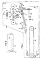
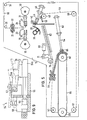
- Fig. 3 - 6 die Folienverarbeitungsmaschine nach Fig. 2 in verschiedenen Arbeitsstellungen,
- Fig. 7 die Stapelvorrichtung nach Fig. 2 in Seitenansicht und teilweiser Darstellung,
- Fig. 8 den Niederschläger nach Fig. 2 in anderer Sicht und teilweiser Darstellung,
- Fig. 9 eine teilweise Darstellung des Greiferkopfes in perspektivischer Darstellung nach Fig. 2,
- Fig. 10 das Fallschwert nach Fig. 2 in perspektivischer und teilweiser Darstellung,
- Fig. 11 eine Verarbeitungsmaschine nach Fig. 2 mit abgewandelter Stapelvorrichtung,
- Fig. 12 die Stapelvorrichtung nach Fig. 11 in perspektivischer und teilweiser Darstellung,
- Fig. 13 die Stapelvorrichtung nach Fig. 11 in detaillierter Darstellung,
- Fig. 14 einen vertikalen Schnitt durch eine abgewandelte Beutelherstellungsmaschine,
- Fig. 15 eine Figur 14 gegenüber größere Darstellung,
- Fig. 16 eine Figur 15 gegenüber abgewandelte Lösung,
- Fig. 17 einen Beutelblock in perspektivischer Darstellung,
- Fig. 18 eine Figur 14 gegenüber weitere Abwandlung.
- 1 is a perspective view and substantially schematic of the film processing machine,
- 2 in a vertical section and essentially schematically, the film processing machine according to FIG. 1,
- 3 - 6 the film processing machine according to FIG. 2 in different working positions,
- 7 is a side view and partial representation of the stacking device according to FIG. 2,
- 8 shows the precipitation according to FIG. 2 in a different view and partial representation,
- 9 is a partial view of the gripper head in a perspective view of FIG. 2,
- 10 is a perspective and partial representation of the falling sword according to FIG. 2,
- 11 shows a processing machine according to FIG. 2 with a modified stacking device,
- 12 shows the stacking device according to FIG. 11 in a perspective and partial illustration,
- 13 shows the stacking device according to FIG. 11 in a detailed illustration,
- 14 is a vertical section through a modified bag making machine,
- 15 is a figure 14 compared to a larger representation,
- 16 is a figure 15 compared to a modified solution,
- 17 a bag block in a perspective view,
- 18 shows a FIG. 14 with respect to a further modification.
Nach Fig. 1 hat die Folienverarbeitungsmaschine 10 die Schweiß- und Stapeleinrichtung 11 mit den Seitenwangen 12 und 13 größerer Höhe sowie den Ablagetisch 15 mit den Seitenwangen 16 und 17 geringerer Höhe. Der Teil zum Herstellen der Beutel und deren Stapelung kann mit dem Ablagetisch 15 eine bauliche Einheit darstellen. In vielen Fällen ist es jedoch zweckmäßig, den Ablagetisch 15 als getrennte bauliche Einheit herzustellen und der Trennschweißvorrichtung mit der Stapelvorrichtung beizustellen. Dies ist in Fig. 1 schematisch durch die gestrichelte Linie 18, 18a angedeutet. Diese Ausführungen zeigen zugleich, daß der Ablagetisch 15, der zugleich mit einer später noch zu beschreibenden hin- und hergehenden Greifvorrichtung versehen ist, an Folienvarbeitungsmaschinen unterschiedlicher Ausbildung angebracht werden kann. Dies wird nachfolgend auch in Verbindung mit Fig. 11 beschrieben werden.1, the
Die in den nachfolgenden Figuren 2 bis b dargestellten Elemente sind in den Seitenwandungen 13 und 14 bzw. 15 und 17 gelagert, Die Figuren 2 bis 6 zeigen zeichnerisch lediglich die Lagerung in den Wandungen 13 und 15.The elements shown in the following FIGS. 2 to b are mounted in the
Die zu verarbeitende doppellagige Folie 19 wird über eine erste Umlenkrolle 20 und zweite Umlenkrolle 20a dem Vorzugswalzenpaar 21, 22 zugeführt. Sie gelangt zwischen den Blaskamm-Röhrchen 23 und 24 hindurch zu der Trennschweißeinrichtung 25, bestehend aus den Schweißbalken 26 und 27, die über zugeordnete Stege 28, 29 mit Rollen 30, 31 an den Nocken 32 und 33 anliegen, die über entsprechende Antriebswellen 34 und 35 angetrieben sind. Der Schweißbalken 27 ist mit einem Messer 36 versehen. Der Schweißbalken 26 hat eine entsprechende längsverlaufende Ausnehmung. Es sei bemerkt, daß die Trenn-Schweißeinrichtung bekannt ist. Sie kann durch eine andere Trenn- und Schweißeinrichtung ersetzt sein.The double-
Unterhalb der Trenn-Schweißeinrichtung ist der rotierende Niederschläger 37 vorhanden, der aus dem Hohlrohr 38 und dem sich über die Länge des Rohres 38 auf einer etwa Kreislinie gebogenen Blechstreifen 39 besteht. Vorhanden sind von dem Hohlrohr 38 ausgehende sich über die Länge erstreckende Blasdüsen 40. Diese können in Gestalt eines längsverlaufenden Schlitzes vorhanden sein. Es kann sich auch um Bohrungen handeln, die in geringem Abstand hintereinander in einer oder in zwei Reihen vorhanden sind.Below the separating welding device, there is the
Zwei Lochreihen an Ausblasdüsen 40, 40a usw. sind in Figur 8 dargestellt. Der Niederschläger wirkt zusammen mit der Stapeleinrichtung, ':e zunächst aus einer sich parallel zum Rohr 38 sowie über die Breite der Maschine erstreckenden Leiste 41 besteht, die über ein Blech 42 an der Wandung 13 und entsprechend auch an der Wandung 14 angeschraubt ist, wie dies aus Figur 7 hervorgeht.Two rows of holes on blow-out
Hinter der Leiste 41 ist die Nadelleiste 43 angeordnet, die nach vorne in Richtung zu dem Niederschläger Nadeln 44 und, wie Figur 7 zeigt, in Abständen eine Vielzahl von Nadeln 44a und 44b hat. Die Nadelleiste ist an beiden Enden befestigt an der Kolbenstange 45 eines Pneumatikzylinders 46, der über Verbindungselemente an der Wandung 13 befestigt ist. Dadurch ist die Nadelleiste zurückziehbar, wie später noch beschrieben wird. Die Leiste 41 hat nach unten im Bereich der Nadeln 44 offene Ausnehmungen 47, 47a, während das Blech 39 gegenüberliegende, nach außen offene Ausnehmungen 48, 48a hat.Arranged behind the
In den Seitenwandungen 13, 16 sind Kettenräder 49, 50, 51 und 52 gelagert, die eine Kette 53 tragen. Die Kettenräder 49 und 52 sind mit auskuppelbaren Antrieben versehen. An den Seitenteilen 14 und 17 ist eine spiegelbildliche Anordnung vorhanden. Die Kette 53 trägt, wie auch aus Figur 9 zu ersehen ist, einen Greiferbalken 54, der aus dem oberen Balken 54a und dem unteren Balken 54b besteht. die zangenartig bewegbar sind. Nach Figur 9 besteht der untere Balken aus einem Querträger 55, der an seinen beiden Enden eine Kolben-Zylinder-Anordnung 56 trägt, damit über die Kolbenstange die Leiste 54b in angegebener Doppelpfeilrichtung verschiebbar ist. Der obere Balken besteht aus einzelnen Abschnitten. Diese sind um die Achse 57 über eine Kolben-Zylinder-Anordnung 58 an-und absenkbar. Eine nicht dargestellte Zugfeder sichert als Ausgangsstellung die Offenstellung. Die Balken haben an den einander zugekehrten Innenflächen gegenüberliegende und in Abständen befindliche Reihen an Höckern 59. Zwischen diesen Höckern mit flachen schräg anlaufenden Keilflächen greift ein in Gestalt eines Bleches ausgebildetes Schwert 59 ein, das sich zwischen den Seitenwangen 13 und 14 erstreckt und an der Seitenwange 13 über einen Flansch 60 befestigt ist. Dieses Schwert hat entsprechend der Darstellung in Figur 10 in Abständen befindliche Ausnehmungen 61, 61a die so bemessen und in einem solchen Abstand angeordnet sind, daß zwischen diesen die vorerwähnten Höcker des Greiferbalkens eingreifen können. Der Greiferbalken 54 ist an der Seitenwandung 13 innerhalb einer Schiene 62 geführt.
Die in Figur 9 dargestellte Lösung erübrigt, daß am Maschinenrahmen 13 über Befestigungselemente 62, 62a der Lufozylinder 63 befestigt ist, an dessen Kolbenstange 64 eine sich über die Breite der Beutelmaschine erstreckende Klemmleiste 65 angeordnet ist, die zusammenwirkt mit dem Förderband 66, das um die beiden Walzen 67 und 68 geführt ist, die in dem Rahmen 16 und 17 gelagert sind. Die Walze 68 ist mit dem Motorantrieb versehen.The solution shown in Figure 9 is superfluous that the
An den Rahmen 13 ist noch ein weiterer Pneumatikzylinder 69 befestigt, dessen Kolbenstange 70 an dem einen Schenkel 71 eines Winkelhebels 72 gelagert ist, der um die Achse 73 schwenkbar ist und der an seinem vorderen unteren Ende des Schenkels 74 das Kettenrad 75 trägt.A further
Nachdem die für die Funktion wesentlichen Bestandteile der Folienverarbeitungsmaschine beschrieben sind, sei nunmehr auf die Arbeitsweise in Verbindung mit den Figuren 2 bis 6 eingegangen.After the components of the film processing machine that are essential for the function have been described, the mode of operation in connection with FIGS. 2 to 6 will now be discussed.
Von der Folienbahn 19 werden durch die Trenn-Schweiß-Einrichtung 25 einzelne Beutel hergestellt und abgetrennt. Dabei steht der Niederschläger 37 in der in Figur 2 angegebenen Wartestellung. Bevor die Schweißbalken 26 und 27 den vom Schlauch abgetrennten Beutel freigeben, ist dieser durch die Saugöffnungen 40 am Niederschläger festgehalten. Dieser wird dann in angegebener Pfeilrichtung 76 im Uhrzeigersinn gedreht. Dabei schlägt das äußere Ende des Bleches 39, wie aus Figur 3 hervorgeht, die obere Kante des Beutels auf die über die Leiste 41 zum Beutel hin vorstehenden Stifte 44 auf. Da der Beutel auf dem Stift aufgeschlagen ist, wird er bei weiterer Rotation der Schlagleiste von dieser gelöst, wie das in Figur 3 angedeutet ist. Nachdem auf diese Weise eine vorbestimmte Anzahl von Beuteln aufgestapelt worden ist, wird über die Kette 53 durch den Antrieb des Kettenrades 49 der Greifer-Balken in Richtung zu dem Beutelstapel bewegt, und zwar so weit, daß das Schwert 59 zwischen die Balken 54a und 54b eingreift und die Folienlagen des Stapels damit die Zange öffnen. Der Beutelstapel wird somit gefaltet. Mit dem Zurückfahren des Greiferbalkens wandert die Zange aus dem Bereich des Schwertes mit dem Ergebnis, daß die Zange sich unter der Wirkung der Zugfeder 47 schließt und die Beutel des Stapels dabei festhält.25 individual bags are produced and separated from the
Entsprechend der Darstellung in Figur 6 wird der Greiferbalken durch den Antrieb des Kettenrades 52 so weit über das Band 66 gefahren, daß das untere Ende des "tutelstapels noch im Bereich der Umlenkwalze 67 vorhanden ist. Dort wird das untere Ende des Beutelstapels durch die Klemmleiste 65 des Pneumatikzylinders 63 festgeklemmt mit dem Ergebnis, daß bei weiterer Bewegung des Greifer-Balkens 54 der Beutelblock aus der Zange herausgezogen wird und damit auf das Obertrum 66a des Bandes abgelegt wird, das in angegebener Pfeilrichtung 77 absatzweise bewegbar ist. Sofern Beutelstapel nur kurzer Länge abgelegt werden, dann soll der Greiferbalken 54 einen geringeren Höhenabstand zu dem Obertrum 66a des Bandes haben. Um dies zu erreichen, wird über den Pneumatikzylinder 69 und der Kolbenstange 70 und dem Hebel 72 das Kettenrad 75 in angegebener Drehrichtung 77a nach unten bewegt, so daß der Greiferbalken einen geringeren Höhenabstand zur Ablage hat. Vorhanden sind entsprechende die Kettenlänge ausgleichende Elemente.According to the illustration in FIG. 6, the gripper bar is driven so far over the
Figur 6 zeigt, daß der Greiferbalken 54 bereits wieder in seine Wartestellung zurückgefahren worden ist, um bald den nächsten Beutel zu ergreifen. Der Klemmbalken 65 klemmt noch den Beutelstapel an der Walze 67 fest, wobei der Beutelstapel noch durch ein Stanzmesser 78, angetrieben durch die Kolbenstange 79 des Pneumatikzylinders 80, gestanzt wird.FIG. 6 shows that the
Es ist zu ersehen, daß in keiner Phase des Bearbeitungsablaufes weder der einzelne Beutel noch der Stapel an Beuteln frei war, sondern bei allen seinen Bewegungsabläufen gehalten wurde. Dadurch ist ein genaues Ausrichten möglich. Auch ist mit dieser Lösung die Verarbeitung verschiedenartigster Beutelmaterialien in Bezug auf chemische Zusammensetzung, Flexibilität und sonstiger physikalischer Eigenschaften und unterschiedlicher Beutelformate, insbesondere in Bezug auf die Länge, möglich.It can be seen that in no phase of the processing sequence was neither the individual bag nor the stack of bags free, but was kept in all of its movements. This makes it an accurate one Alignment possible. With this solution it is also possible to process a wide variety of bag materials in terms of chemical composition, flexibility and other physical properties and different bag formats, especially with regard to length.
Die Ausbildung des sich über die Breite der Maschine erstreckenden Greiferbalkens, der mit den Gegenbalken auf der anderen Seite der Beutelstapel, besonders vorteilhaft in Gestalt eines Schwertes, das ortsfest gelagert ist, zusammenwirkt, ermöglicht die Erfassung der Beutelstapel unabhängig von der Breite der Beutelstapel. So ist verständlich, daß auch nebeneinander zwei oder noch mehr Beutelstapel gleichzeitig transportiert werden können, weil die erfindungsgemäße Lösung hier keine Beschränkung erkennen läßt.The design of the gripper bar, which extends over the width of the machine and which cooperates with the counterbars on the other side of the stack of bags, particularly advantageously in the form of a sword, which is mounted in a stationary manner, enables the stack of bags to be detected independently of the width of the stack of bags. It is thus understandable that two or more stacks of bags can also be transported side by side at the same time, because the solution according to the invention shows no restriction here.
Fig. 11 zeigt, daß der Greifer-Balken in Verbindung mit dem Gegenbalken auf der anderen Seite der Beutel, vorteilhaft in Gestalt des ortsfesten Schwertes, auch zwei gegenüberliegende Beutelstapel erfassen und wegtransportieren kann, weil auch in dieser Hinsicht die erfindungsgemäße Lösung keinerlei Beschränkung unterworfen ist.Fig. 11 shows that the gripper bar in connection with the counter bar on the other side of the bag, advantageously in the form of the fixed sword, can also grasp and transport away two opposite stacks of bags, because the solution according to the invention is not subject to any restrictions in this regard either .
Fig. 11 zeigt, daß unterhalb der Trenn-Schweißvorrichtung zwei STapelablagen vorhanden sind, so daß zu der bisher beschriebenen Stapelablage spiegelbildlich die Stapelablage 41a, 42a mit der Nadelleiste 43a und deren Antrieb durch den Zylinder 46a hinzukommt. Es erfolgt die Arbeitsweise, daß der erste Beutel auf der ersten Stapeleinrichtung 41a, der zweite Beutel auf die zweite Stapeleinrichtung 41, der dritte Beutel wiederum auf der ersten STapeleinrichtung 41 und so weiter aufgeschlagen wird, und zwar durch einen Schläger 81, der entsprechend der Darstellung in den Figuren 12 und 13 eine Leiste 82 hat, die sich über die Breite der Folienverarbeitungsmaschine erstreckt und an beiden Enden an einem Arm 83 gelagert ist, der an der Seitenwandung 13 an einem Drehzapfen 84 in angegebener Pfeilrichtung 85 hin- und hergehend schwenkbar gelagert ist. In Fig. 12 sind mit den Bezugszeichen 41 und 41a die Leisten bezeichnet, zwischen denen nach unten offenen Aussparungen 47 die Nadeln 44 durchgreifen.Fig. 11 shows that below the separating welding device there are two stacking trays, so that the stacking
Die Wirkungsweise sei anhand von Fig. 13 beschrieben.The mode of operation will be described with reference to FIG. 13.
Sofern durch die Schweißbalken 26 und 27 Beutel mit einer Seitennaht oder einer doppelten Bodennaht hergestellt werden und die Trennschweißeinrichtung zwei in einem Abstand hintereinander befindliche Schweißeinrichtungen 86, 86a und 87, 87a hat, dann ist es möglich, daß der Beutel oder Sack bei seinem Aufstapeln im Bereich der Stapeleinrichtung eine noch erhitzte Schweißnaht hat.If bags with a side seam or a double bottom seam are produced by the welding bars 26 and 27 and the separating welding device has two
S ofern die Beutel mit geringer Taktzahl, beispielsweise 50 Beutel pro Minute hergestellt werden, dann ist zufolge der hier langsamen Verarbeitungszeit ein ausreichendes Abkühlen der Schweißnähte gegeben, insbesondere sofern entsprechend der Darstellung nach Fig. 2 die Luftblasröhrchen 23 und 24 vorhanden sind. Um eine höhere Takzahl zu erreichen, wird vorgeschlagen,If the pouches are produced with a low cycle rate, for example 50 pouches per minute, then the weld seams are sufficiently cooled due to the slow processing time here, in particular if the air-blowing
den ersten Beutel beispielsweise auf die Ablage 41a mit den Stiften 44a aufzuschlagen und den nachfolgenden Beutel auf die Ablage 41 mit den dortigen Stiften 44. Es erfolgt somit ein abwechselndes Aufschlagen auf die eine Ablage durch den einen Beutel und auf die gegenüberliegende Ablage durch den nachfolgenden Beutel.to open the first bag, for example, on the
Um dies zu erreichen, ist der Schläger im Bereich unterhalb der Schweiß- einrichtung mit einer jeden Seite zugeordneten Ausblasöffnung 88 und 89 versehen. Sofern der Schläger nach links in Richtung zur Ablage 41a bewegt wird, dann blasen die Auslässe 88. Wird er in Richtung der Ablage 41 nach rechts bewegt, dann blasen die Auslässe 89, die sich über die gesamte Länge der Schlagleiste erstrecken. Sie können aus einem durchgehenden Schlitz, aber auch aus in dichtem Abstand befindlichen einzelnen Bohrungen bestehen. Um den notwendig schnellen Wechsel des Pendelschlägers zu erreichen, sind an den Armen, in Fig. 13 dargestellt, dem Arm 83, über Drehgelenke 90 und 91 Kolbenstangen 92 und 93 von Pneumatikzylindern 94 und 95 angeordnet, die über zugeordnete Halterungen 96 und 97 an Drehachsen 98 und 99 schwenkbar sind.In order to achieve this, the bat is provided in the region below the welding device with a blow-out
Fig. 13 zeigt ebenfalls das Schwert 59 in Verbindung mit der Zange aus den Balkenteilen 54a und 54b. Diese sind nach Fig. 13 an einer Kolbenstange 100 befestigt, weil der in den Zeichnungen dargestellte Kettenantrieb, der den Greiferbalken trägt, auch durch einen Pneumatikantrieb ersetzt sein kann.Fig. 13 also shows the
Figur 14 zeigt die gegenüber der Figur 11 abgewandelte Lösung mit der Maßgabe, daß ein Schläger 101 angewendet ist, der in Horizontalebene entsprechend der Doppelpfeilrichtung 102 hin- und hergehend bewegt ist. Vorhanden sind die Stifte 44 und 44a an zugeordneten, gegenüberliegenden Kolbenstangen der Zylinder 46 und 46a.FIG. 14 shows the solution modified compared to FIG. 11 with the proviso that a
Nach den Figuren 15 und 16 ist unterhalb der Trenn- und Schweißvorrichtung26 und 27 die Stapeleinrichtung 41 und 41a vorhanden mit den vertikalen Bereichen 103 und 103a sowie horizontalen Bereichen 104 und 104a. Der Schläger 101 ist an seiner Unterseite oder an seiner Oberseite befestigt an einem Förderband 105, das über Umlenkrollen 106 und 107 hin- und hergehend bewegt wird, so daß die Beutel nacheinanderfolgend abwechselnd auf die Stapeleinrichtung 41 und 41a aufgestapelt werden.According to FIGS. 15 and 16, the stacking
Den horizontalen Stapelflächen 104 sowie 104a sind Werkzeuge 108 bzw. 108a zugeordnet, die Lochungen, Stanzungen, Perforationen oder vorteilhaft Schweißungen ausführen. Es können aber lediglich auf Festhalte-Einrichtungen sein, deren Wirkungsweise in Verbindung mit Figur 16 beschrieben wird.The horizontal stacking
Figur 16 zeigt die Bewegung des Schlägers 101 in der Pfeilrichtung 109 nach rechts mit der Maßgabe, daß das obere Ende des Beutels 110 zufolge des plötzlichen Schlages nach links abgebogen ist. Durch das Ausblasen von Luft aus der Düse 101a wird dann das obere Ende des Beutels, wie in gestrichelter Linie dargestellt ist, nach rechts abgelenkt. An der vertikalen Schiene 103 ist eine Beutelklemmleiste 111 angeordnet, die einen horizontalen Schenkel 112 und einen vertikalen Schenkel 113 hat. Der vertikale Schenkel ist mit einer Führung versehen, damit entgegen dem Druck einer Schraubenlinienfeder 114 eine Rückfederung stattfindet. Sobald der Schläger 101 oder gegebenenfalls eine an diesem angeordnete vorspringende Leiste 115 den Beutel an der Staplleiste 112 angedrückt hat, dann ist zugleich mit diesem Zeitpunkt oder kurze Zeit später auch das obere Beutelende auf der Arbeitsfläche 104 bzw. dem darauf vorherigen Beutelende aufgelegt. Dann geht die Niederhaltevorrichtung 108 nach Figur 2 oder ein um die Achse 115 drehbarer Festhalter nach unten und klemmt das obere Beutelende fest. Dadurch ist die Lage des Beutels und zufolge der horizontalen Erstreckung der oberen Auflagefläche die Lage des Beutelblocks gesichert. Auf diese Weise kann das Bearbeiten erfolgen.FIG. 16 shows the movement of the
Aus Figur 16 ist zu ersehen, daß wahlweise nach dem einen System aber auch lediglich mit den Stiften gearbeitet werden kann.It can be seen from FIG. 16 that either one of the two systems can be used to work with the pins.
Figur 17 zeigt Beutel, die durch Schweißnähte 117 in der Weise zu einem Block miteinander verbunden sind, daß in an sich bekannter Weise der nachfolgende Beutel mit dem vorhergehenden Beutel des Beutelblocks durch eine Schweißnaht verbunden wird. Dazu sind die beiden Schweißbalken 108, 108a vorhanden.An diesen sind jeweils elastische Bleche 117, 117a angeordnet, die mit dem Niedergehen des Schweißbalkens die Luft zwischen den Beuteln austreiben und somit zusammengedrückte Stapel ergeben, die das Verschweißen zum Stapel begünstigen und nahezu fluchtende Kanten 118, 118a ergeben. Die Niederhalter oder Festhalter 116, 116a haben horizontale Auflageflächen 119, 119a für die stirnseitigen Kanten der Beutel, so daß deren gegebenenfalls noch klebefähigen Schweißnähte 120, erhalten, durch die die Schweiß- einrichtung 26, 27 nicht einander anbacken können. Zum Festhalten des Beutelstapels wirken die Schweißbalken 108 und Festhaltevorrichtung abwechselnd untereinander, so daß es keiner besonderen Nadeln 44, 44a bedarf.FIG. 17 shows bags which are connected to one another by a
Claims (31)
dadurch gekennzeichnet , daß die Stapeleinrichtung eine horizontale Arbeitsfläche (104) aufweist, mit der in Verbindung mit Werkzeugen (108, 108a) eine Weiterbearbeitung der Beutel oder des Beutelstapels erfolgt.22. Device for stacking bags or similar packaging made of thermoplastic plastic film, which is attached to the separating and welding device working in the horizontal plane and has a stacking device with a reciprocating bat, and below the separating and sealing device and to this, the stacking device is arranged in mirror image of the vertical plane of the bag feed and a racket of this type is present, which places the first bag on the first stacking device and the second bag on the opposite stacking device and the third bag on the first stacking device, the fourth bag hits the second stacking device and in this way until a predetermined number of bags has opened,
characterized in that the stacking device has a horizontal work surface (104) with which the bags or the bag stack are further processed in connection with tools (108, 108a).
Applications Claiming Priority (4)
| Application Number | Priority Date | Filing Date | Title |
|---|---|---|---|
| DE3327552 | 1983-07-30 | ||
| DE19833327552 DE3327552A1 (en) | 1983-07-30 | 1983-07-30 | Film processing machine |
| DE3336108A DE3336108A1 (en) | 1983-10-05 | 1983-10-05 | Device for stacking bags or similar packages |
| DE3336108 | 1983-10-05 |
Publications (2)
| Publication Number | Publication Date |
|---|---|
| EP0133286A1 true EP0133286A1 (en) | 1985-02-20 |
| EP0133286B1 EP0133286B1 (en) | 1988-10-26 |
Family
ID=25812765
Family Applications (1)
| Application Number | Title | Priority Date | Filing Date |
|---|---|---|---|
| EP84108770A Expired EP0133286B1 (en) | 1983-07-30 | 1984-07-25 | Film processing machine |
Country Status (2)
| Country | Link |
|---|---|
| EP (1) | EP0133286B1 (en) |
| DE (1) | DE3474790D1 (en) |
Cited By (3)
| Publication number | Priority date | Publication date | Assignee | Title |
|---|---|---|---|---|
| NL1008447C2 (en) * | 1998-03-02 | 1999-09-03 | Patchville Corp N V | Device for manufacturing and packaging polyethylene bags, especially for use in freezing food. |
| US6977178B2 (en) | 2000-09-06 | 2005-12-20 | Transnetyx, Inc. | System and method for transgenic and targeted mutagenesis screening |
| US10155923B2 (en) | 2009-03-20 | 2018-12-18 | International Business Machines Corporation | Microorganism culture device and method of operation thereof |
Families Citing this family (1)
| Publication number | Priority date | Publication date | Assignee | Title |
|---|---|---|---|---|
| FR2592333A1 (en) * | 1986-01-02 | 1987-07-03 | Lagain Georges | INSTALLATION FOR MANUFACTURING AND STACKING BAGS, BAGS, ETC. IN THERMOPLASTIC MATTER |
Citations (5)
| Publication number | Priority date | Publication date | Assignee | Title |
|---|---|---|---|---|
| DE2305800A1 (en) * | 1972-02-09 | 1973-08-16 | Scae Sa | DEVICE FOR REGULAR BANDING OF A MULTIPLE NUMBER OF BAGS OR OTHER THERMOPLASTIC FILM AND THE LIKE |
| DE2233408A1 (en) * | 1972-07-07 | 1973-10-31 | Hans Lehmacher | METHOD AND DEVICE FOR APPLYING THE BAGS STACKED INTO A BLOCK |
| DE2141045B2 (en) * | 1971-08-17 | 1974-02-07 | Hans 5216 Niederkassel Lehmacher | Method and device for the production of bags stacked to form a block and connected to one another by welding in the edge area. packagings |
| US4223883A (en) * | 1978-06-19 | 1980-09-23 | Chase Bag Company | Bag tube-feeder system |
| DE3211217A1 (en) * | 1982-03-26 | 1983-10-06 | Franz Bendig | METHOD AND DEVICE FOR PRODUCING AND STACKING BAGS FROM THERMOPLASTIC PLASTIC FILM |
-
1984
- 1984-07-25 EP EP84108770A patent/EP0133286B1/en not_active Expired
- 1984-07-25 DE DE8484108770T patent/DE3474790D1/en not_active Expired
Patent Citations (5)
| Publication number | Priority date | Publication date | Assignee | Title |
|---|---|---|---|---|
| DE2141045B2 (en) * | 1971-08-17 | 1974-02-07 | Hans 5216 Niederkassel Lehmacher | Method and device for the production of bags stacked to form a block and connected to one another by welding in the edge area. packagings |
| DE2305800A1 (en) * | 1972-02-09 | 1973-08-16 | Scae Sa | DEVICE FOR REGULAR BANDING OF A MULTIPLE NUMBER OF BAGS OR OTHER THERMOPLASTIC FILM AND THE LIKE |
| DE2233408A1 (en) * | 1972-07-07 | 1973-10-31 | Hans Lehmacher | METHOD AND DEVICE FOR APPLYING THE BAGS STACKED INTO A BLOCK |
| US4223883A (en) * | 1978-06-19 | 1980-09-23 | Chase Bag Company | Bag tube-feeder system |
| DE3211217A1 (en) * | 1982-03-26 | 1983-10-06 | Franz Bendig | METHOD AND DEVICE FOR PRODUCING AND STACKING BAGS FROM THERMOPLASTIC PLASTIC FILM |
Cited By (3)
| Publication number | Priority date | Publication date | Assignee | Title |
|---|---|---|---|---|
| NL1008447C2 (en) * | 1998-03-02 | 1999-09-03 | Patchville Corp N V | Device for manufacturing and packaging polyethylene bags, especially for use in freezing food. |
| US6977178B2 (en) | 2000-09-06 | 2005-12-20 | Transnetyx, Inc. | System and method for transgenic and targeted mutagenesis screening |
| US10155923B2 (en) | 2009-03-20 | 2018-12-18 | International Business Machines Corporation | Microorganism culture device and method of operation thereof |
Also Published As
| Publication number | Publication date |
|---|---|
| EP0133286B1 (en) | 1988-10-26 |
| DE3474790D1 (en) | 1988-12-01 |
Similar Documents
| Publication | Publication Date | Title |
|---|---|---|
| DE2352666C3 (en) | Device for packaging flat objects such as bags, garbage bags or the like. in packing bag | |
| DE2833232C2 (en) | Device for producing shirt bags from a plastic tubular film web provided with gussets | |
| DE2825722C2 (en) | Device for the production of bags or sacks and for their deposition in imbricated formation | |
| DE3138221A1 (en) | METHOD FOR PRODUCING THERMOPLASTIC BAGS | |
| EP0059420A1 (en) | Method and means for manufacturing stacks of bags | |
| DE2629065B2 (en) | Device for the automatic filling and closing of sacks | |
| EP1623926B1 (en) | Method and machine for producing and filling bags | |
| DE2819887C2 (en) | Device for producing an arrangement having a carrier tape and flat workpieces arranged on top of one another in scales for storing the workpieces | |
| DE2618690C3 (en) | Packing machine | |
| DE2902519C2 (en) | Device for depositing sections welded from a film web | |
| EP1153834B1 (en) | Method for continuously manufacturing infusion bags | |
| DE4127854C2 (en) | Device for feeding two plate-shaped blanks to a deep-drawing machine | |
| EP0133286B1 (en) | Film processing machine | |
| EP1201539A1 (en) | Device for making and preferably filling and closing of thermoplastic bags | |
| EP0294582B1 (en) | Device for producing thermoplastic bags or sacks from a tubular sheath supplied preferably with sidefolds | |
| WO2009121542A1 (en) | Device and method for producing bags from pieces of tubing | |
| EP0925910B1 (en) | Method and device for making stacks of bags made from a continuous plastic web, in particular bags with an handle | |
| EP0506645A1 (en) | Apparatus for fabrication of battery plate envelopes | |
| EP0872421B1 (en) | Cutting and transferring station of a flat-bag handling machine operating stepwise | |
| EP1107864B1 (en) | Method and device for interlocking stackwise plastic bags, especially bags for automatic machines, by welding | |
| EP0544078B1 (en) | Device for cutting off tubular plastic sheets containing transverse welds from a continuous sheet, and stacking them | |
| DE1265563C2 (en) | Machine for the production of open plastic bags | |
| EP0516979A1 (en) | Method for making, filling and closing bags | |
| DE3327552A1 (en) | Film processing machine | |
| EP2758329B1 (en) | Device and method for stacking bags made of plastic film |
Legal Events
| Date | Code | Title | Description |
|---|---|---|---|
| PUAI | Public reference made under article 153(3) epc to a published international application that has entered the european phase |
Free format text: ORIGINAL CODE: 0009012 |
|
| AK | Designated contracting states |
Designated state(s): BE DE FR IT |
|
| 17P | Request for examination filed |
Effective date: 19850802 |
|
| 17Q | First examination report despatched |
Effective date: 19860416 |
|
| GRAA | (expected) grant |
Free format text: ORIGINAL CODE: 0009210 |
|
| AK | Designated contracting states |
Kind code of ref document: B1 Designated state(s): BE DE FR IT |
|
| ITF | It: translation for a ep patent filed |
Owner name: ING. A. GIAMBROCONO & C. S.R.L. |
|
| REF | Corresponds to: |
Ref document number: 3474790 Country of ref document: DE Date of ref document: 19881201 |
|
| ET | Fr: translation filed | ||
| PGFP | Annual fee paid to national office [announced via postgrant information from national office to epo] |
Ref country code: BE Payment date: 19890621 Year of fee payment: 6 |
|
| PGFP | Annual fee paid to national office [announced via postgrant information from national office to epo] |
Ref country code: FR Payment date: 19890728 Year of fee payment: 6 |
|
| ITTA | It: last paid annual fee | ||
| PGFP | Annual fee paid to national office [announced via postgrant information from national office to epo] |
Ref country code: DE Payment date: 19890809 Year of fee payment: 6 |
|
| PLBE | No opposition filed within time limit |
Free format text: ORIGINAL CODE: 0009261 |
|
| STAA | Information on the status of an ep patent application or granted ep patent |
Free format text: STATUS: NO OPPOSITION FILED WITHIN TIME LIMIT |
|
| 26N | No opposition filed | ||
| PG25 | Lapsed in a contracting state [announced via postgrant information from national office to epo] |
Ref country code: BE Effective date: 19900731 |
|
| BERE | Be: lapsed |
Owner name: BENDIG FRANZ Effective date: 19900731 Owner name: BENDIG JOHANNES Effective date: 19900731 |
|
| PG25 | Lapsed in a contracting state [announced via postgrant information from national office to epo] |
Ref country code: DE Effective date: 19910403 |
|
| PG25 | Lapsed in a contracting state [announced via postgrant information from national office to epo] |
Ref country code: FR Effective date: 19950731 |
|
| REG | Reference to a national code |
Ref country code: FR Ref legal event code: ST |
|
| PG25 | Lapsed in a contracting state [announced via postgrant information from national office to epo] |
Ref country code: FR Effective date: 19900731 |