EP0133220A2 - Electric conductor - Google Patents
Electric conductor Download PDFInfo
- Publication number
- EP0133220A2 EP0133220A2 EP84107968A EP84107968A EP0133220A2 EP 0133220 A2 EP0133220 A2 EP 0133220A2 EP 84107968 A EP84107968 A EP 84107968A EP 84107968 A EP84107968 A EP 84107968A EP 0133220 A2 EP0133220 A2 EP 0133220A2
- Authority
- EP
- European Patent Office
- Prior art keywords
- electrical conductor
- individual
- wires
- conductor according
- round
- Prior art date
- Legal status (The legal status is an assumption and is not a legal conclusion. Google has not performed a legal analysis and makes no representation as to the accuracy of the status listed.)
- Withdrawn
Links
Images

Classifications
-
- H—ELECTRICITY
- H01—ELECTRIC ELEMENTS
- H01F—MAGNETS; INDUCTANCES; TRANSFORMERS; SELECTION OF MATERIALS FOR THEIR MAGNETIC PROPERTIES
- H01F27/00—Details of transformers or inductances, in general
- H01F27/28—Coils; Windings; Conductive connections
- H01F27/2823—Wires
Definitions
- the invention relates to an electrical conductor with Roebel characteristics, which is stranded from in particular six individual elements without a central core.
- the invention has for its object to eliminate the aforementioned disadvantages of the prior art and to provide a conductor in which, using inexpensively available elements, the current displacement (skin effect) and other magnetic losses are considerably reduced, even at high frequencies are.
- the main area of application for the conductors according to the invention is coils for transformers, chokes and high-energy magnets.
- the ropes are each composed of 50 to 150 individual enamelled round wires. Higher or lower values could also be used, but if a number below 50 is used, the individual wire becomes too thick for certain cross-sectional requirements and the rope element and the finished conductor made from it are too inflexible. On the other hand, a number of over 150 wires will in most cases be too complex to manufacture.
- the type of stranding of the individual elements is not important with regard to the Röbel effect, the stranding can therefore also be done with a core and be multi-layered.
- a plurality of conductors are arranged around a central, preferably metallic, cooling duct, meet the requirements of the single-conductor transposition according to Roebel, consist of elements from a large number of enamelled wires and are reshaped.
- the individual Enameled wires are additionally coated with an initially elastic mass, which hardens when heated, so that the conductors together with the cooling channel form a firmly connected unit which retains the shape once assumed.
- Thermoplastics as well as thermosets can be considered as the first elastic mass that hardens when heated. In the former case, polyamides are preferred, in the latter epoxy materials, compatibility with the insulating varnish underneath being required.
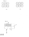
- the individual images show cross sections through the finished conductor within one lay length (360 ° basket rotation).
- Figure 1a corresponds to the starting point with 0 ° basket rotation
- Figure 1b a rotation by 60 °
- Figure 1c corresponding to 120 °
- Figure 1d corresponding to 180 °
- Figure 1f finally corresponding to 300 °
- the transposition is clearly evident from the numbers 1 to 6 of the individual elements.
- the individual elements 1 to 6 can be solid individual wires or, in turn, elements that are stranded in one or more layers (possibly without Roebel characteristics).
- the individual wires can be customary enamelled wires with conductors made of copper or non-ferrous metals or non-ferrous alloys and an insulating layer preferably made of suitable thermosets, in particular polyvinyl acetal or polyesterimides for even higher thermal loads.
- FIGS. 2 and 3 also show a type of deformation of the conductor according to FIG. 1, namely a cross section through a rectangular shaped finished conductor.
- Figure 2a shows the starting point
- Figure 2b shows the cross section after half a lay length corresponding to 180 ° or corresponding to Figure 1d.
- Figure 2 is idealized
- Figure 3 is shown in practice.
- FIG. 3 shows a cross section through a typical finished conductor.
- the elements are not wires, but ropes, denoted by 7, each rope again being made from nine enamelled wires 8. It goes without saying that the ropes 7 are, however, generally made from many more individual wires 8, a multi-layer stranding with core (without locking) being the normal case.
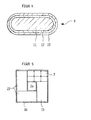
- a single enamelled wire (8) is shown in FIG.
- the wire core itself is designated 11, the lacquer layer 12.
- This is applied in a known manner from thermoset solutions or dispersions, but in individual cases a thermoplastic extruded layer can also be applied as insulation instead.
- a layer 13 can now additionally be applied, in particular extruded, onto the layer 12, which layer consists of an initially elastic mass which hardens after heating. Such an additional coating is advantageous if the conductor is to be held firmly together in this way or if it is to be kept in a desired shape after being deformed on site.
- FIG. 5 finally shows a conductor with a cooling channel 20, which can be, for example, a bare square copper tube.
- a cooling channel 20 can be, for example, a bare square copper tube.
- Four rectangular conductors 15 are arranged around the latter, the structure of which can be seen in FIG.
- Each conductor consists of six elements 7, as indicated in the figure.
- the dimensions of the four conductors 15 are chosen so that the overall structure is again one has a square cross section.
- the four conductors 15 are wrapped with a glass braid tape 16. It goes without saying that each of the conductors 15 has been blown apart, the elements 7 need not meet the Roebel transposition requirement.
- the (individual) conductors are formed in a round form, preferably from six elements, during the round stranding and can then be e.g. are deformed into a rectangular, square, trapezoidal shape, depending on the geometric requirements for the construction of conductors with a cooling channel.
Landscapes
- Engineering & Computer Science (AREA)
- Power Engineering (AREA)
- Coils Of Transformers For General Uses (AREA)
- Insulating Of Coils (AREA)
Abstract
Description
Die Erfindung betrifft einen elektrischen Leiter mit Roebel-Charakteristik, der aus insbesondere sechs Einzelelementen ohne zentralen Kern verseilt ist.The invention relates to an electrical conductor with Roebel characteristics, which is stranded from in particular six individual elements without a central core.
Solche Leiter sind aus dem deutschen Gebrauchsmuster 6 909 855 bekannt. Dort werden sechs blanke Kupferdrähte mit oder ohne einem thermoplastischen Kern verseilt und anschließend derart verformt, daß sich Segmente bilden, wobei der Kern in die Zwischenräume tritt. Dieser Stand der Technik ist jedoch nicht befriedigend. Wird nämlich mit Kern verseilt, läßt sich der Roebel-Effekt nur unvollkommen verwirklichen. Jeder Einzeldraht müßte möglichst mehrmals,Such conductors are known from
bezogen auf die Gesamtlänge des Seiles, die Position aller anderen isolierten Einzelleiter einnehmen bzw. durchlaufen, was im Falle der Verwendung eines Zentralseiles nur in sehr beschränktem Maße möglich ist.based on the total length of the rope, assume or pass through the position of all other isolated individual conductors, which is only possible to a very limited extent if a central rope is used.
Auf der anderen Seite ist die gegenseitige Isolierung der blanken Drähte allein durch die in die Zwischenräume gequetschte Masse keinesfalls ausreichend, so daß jedenfalls für Anwendungen als Spulen und dgl. bei elektrischen Maschinen und Transformatoren erhebliche Wirbelstrcmverluste zu erwarten sind. Wird aber ohne plastischen Kern verseilt, entfällt der Roebel-Effekt deshalb gänzlich, weil die blanken Drähte sich gegenseitig berühren.On the other hand, the mutual insulation of the bare wires by the mass squeezed into the interstices alone is by no means sufficient, so that considerable eddy current losses can be expected in any case for applications as coils and the like in electrical machines and transformers. However, if stranding is carried out without a plastic core, the Roebel effect is completely eliminated because the bare wires touch each other.
Der Erfindung liegt die Aufgabe zugrunde, die vorgenannten Nachteile des Standes der Technik zu beseitigen und einen Leiter zu schaffen, bei dem unter Verwendung von preislich günstig zur Verfügung stehenden Elementen selbst bei hohen Frequenzen die Stromverdrängung (Skin-Effekt) und andere magnetische Verluste erheblich reduziert sind.The invention has for its object to eliminate the aforementioned disadvantages of the prior art and to provide a conductor in which, using inexpensively available elements, the current displacement (skin effect) and other magnetic losses are considerably reduced, even at high frequencies are.
Diese Aufgabe wird bei einem Leiter der eingangs genannten Art erfindungsgemäß dadurch gelöst, daß die Elemente einzelne runde durchgehend isolierte Lackdrähte sind oder Seile aus einer Vielzahl von runden durchgehend isolierten Lackdrähten.This object is achieved according to the invention in a conductor of the type mentioned at the outset in that the elements are individual round, completely insulated enamelled wires or ropes made from a multiplicity of round, completely insulated enamelled wires.
Hauptanwendungsgebiet für die Leiter gemäß der Erfindung sind Spulen für Transformatoren, Drosseln und Hochenergie-Magnete.The main area of application for the conductors according to the invention is coils for transformers, chokes and high-energy magnets.
Bei einer vorteilhaften Ausführungsform der Erfindung setzen sich die Seile aus jeweils 50 bis 150 Einzel-Lackrunddrähten zusammen. Es könnten auch höhere oder niedrigere Werte benutzt werden, jedoch wird bei Verwendung einer Zahl unter 50 der Einzeldraht bei bestimmten Querschnittsanforderungen zu dick und damit das daraus gefertigte Seilelement und der fertige Leiter zu unflexibel. Auf der anderen Seite wird eine Anzahl von über 150 Drähten in den meisten Fällen fertigungstechnisch zu aufwendig sein. Die Verseilart der einzelnen Elemente ist bezüglich des Röbel-Effektes nicht von Bedeutung, die Verseilung kann deshalb auch mit Kern erfolgen und mehrlagig sein.In an advantageous embodiment of the invention, the ropes are each composed of 50 to 150 individual enamelled round wires. Higher or lower values could also be used, but if a number below 50 is used, the individual wire becomes too thick for certain cross-sectional requirements and the rope element and the finished conductor made from it are too inflexible. On the other hand, a number of over 150 wires will in most cases be too complex to manufacture. The type of stranding of the individual elements is not important with regard to the Röbel effect, the stranding can therefore also be done with a core and be multi-layered.
Weiterhin ist es von Vorteil, Einzeldrähte zu verwenden, die eine mechanisch-resistente Lackisolierung aufweisen. Besonders bewährt hat sich Polyvinylacetal wegen seiner besonders hohen Abriebfestigkeit und einer guten Verträglichkeit für viele Kühlmedien, wie sie für elektrische Spulen üblicherweise verwendet werden. Auch Esterimide sind besonders geeignet, vor allem im Falle höherer Temperaturbelastungen. Der aus den Elementen zusammengefügte elektrische Leiter kann verformt werden. Entsprechend ist die Herstellung segmentförmiger Verformungsquerschnitte möglich, wie z.B. Rechteck-, Trapez- und Dreieckform. Bezüglich der Schichtdicken des Lackes empfiehlt sich eine Größenordnung zwischen 25 und 50 µm.Furthermore, it is advantageous to use individual wires that have a mechanically resistant enamel insulation. Polyvinyl acetal has proven particularly useful because of its particularly high abrasion resistance and good compatibility with many cooling media, as are usually used for electrical coils. Esterimides are also particularly suitable, especially in the case of higher temperature loads. The electrical conductor assembled from the elements can be deformed. Accordingly, the production of segment-shaped deformation cross sections is possible, e.g. Rectangular, trapezoidal and triangular shape. With regard to the layer thickness of the lacquer, a range between 25 and 50 µm is recommended.
Schließlich ist es von Vorteil, den fertiggestellten runden oder verformten Leiter zu bewickeln. Besonders empfiehlt sich Glasgewebeband. Die Bewicklung dient als Zusatzisolierung gegenüber spannungführenden Teilen sowie als mechanischer Schutz.Finally, it is advantageous to wind the finished round or deformed conductor. Glass fabric tape is particularly recommended. The wrapping serves as additional insulation against live parts and as mechanical protection.
Weitere vorteilhafte Ausführungsformen sind in weiteren Unteransprüchen gekennzeichnet.Further advantageous embodiments are characterized in further subclaims.
Im Rahmen der Erfindung liegt auch die weiterhin bevorzugte Gestaltung, daß mehrere Leiter um einen zentralen vorzugsweise metallischen Kühlkanal herum angeordnet sind, für sich die Forderung der Einzelleiter-Transposition nach Roebel erfüllen, aus Elementen aus einer Vielzahl von Lackdrähten bestehen und nachverformt sind. Dabei ist es von Vorteil, daß die einzelnen Lackdrähte zusätzlich mit einer zunächst elastischen Masse beschichtet sind, die bei Erwärmung aushärtet, so daß die Leiter samt Kühlkanal eine festverbundene, die einmal eingenommene Form beibehaltende Baueinheit bilden. Als zunächst elastische Masse, die bei Erwärmung aushärtet, können sowohl Thermoplaste wie auch Duroplaste in Frage kommen. Im ersteren Falle sind Polyamide bevorzugt, im letzteren Epoxidmassen, wobei jeweils Verträglichkeit mit dem darunter befindlichen Isolierlack bestehen muß.Within the scope of the invention is also the further preferred design that a plurality of conductors are arranged around a central, preferably metallic, cooling duct, meet the requirements of the single-conductor transposition according to Roebel, consist of elements from a large number of enamelled wires and are reshaped. It is advantageous that the individual Enameled wires are additionally coated with an initially elastic mass, which hardens when heated, so that the conductors together with the cooling channel form a firmly connected unit which retains the shape once assumed. Thermoplastics as well as thermosets can be considered as the first elastic mass that hardens when heated. In the former case, polyamides are preferred, in the latter epoxy materials, compatibility with the insulating varnish underneath being required.
Im folgenden wird die Erfindung anhand eines Ausführungsbeispieles näher erläutert, aus dem sich weitere Merkmal und Vorteile der Erfindung ergeben.The invention is explained in more detail below with the aid of an exemplary embodiment, from which further features and advantages of the invention result.
In der zugehörigen Zeichnung zeigt:
- Fig. 1 einen kernlos verseilten Leiter, an verschiedenen Stellen (a bis f) geschnitten;
- Fig. 2 einen Querschnitt durch einen Leiter gemäß
Figur 1, nach Verformung; - Fig. 3 einen Querschnitt durch einen typischen Leiter nach Verformung;
- Fig. 4 einen einzelnen Lackdraht mit zusätzlicher Beschichtung;
- Fig. 5 einen Gesamtleiter mit Kühlkanal.
- 1 shows a core stranded conductor, cut at different points (a to f);
- 2 shows a cross section through a conductor according to FIG. 1, after deformation;
- 3 shows a cross section through a typical conductor after deformation.
- 4 shows a single enamelled wire with an additional coating;
- Fig. 5 shows an overall conductor with a cooling channel.
In Figur 1 ist der in der Praxis sich einstellende Zustand bei kernloser Verseilung von sechs Elementen gezeigt, wobei abwechselnd die verschiedenen Elemente 1 bis 6 die Mittellage einnehmen und wo - wie ersichtlich - eine echte Transposition der einzelnen Elemente bzw. Drähte 1 bis 6 im Sinne der Roebel=Charakteristik möglich ist. Die Einzelbilder zeigen Querschnitte durch den fertigen Leiter innerhalb einer Schlaglänge (360° Korbdrehung). Figur 1a entspricht dem Ausgangspunkt mit 0° Korbdrehung, Figur 1b einer Drehung um 60°, Figur 1c entsprechend 120°, Figur 1d entsprechend 180°, Figur 1e 240° und Figur 1f schließlich entsprechend 300°, wobei bei 360° Drehung wieder der Ausgangszustand gemäß Figur 1a erreicht wäre. Die Transposition ist durch die Bezifferung 1 bis 6 der einzelnen Elemente deutlich ersichtlich.FIG. 1 shows the state that occurs in practice with the core stranding of six elements, with the
Wie schon ausgeführt, kann es sich bei den einzelnen Elementen 1 bis 6 um massive Einzeldrähte oder aber auch um ihrerseits wieder ein- oder mehrlagig verseilte Elemente (ggf. ohne Roebel-Charakteristik) handeln. Bei den Einzeldrähten kann es sich um übliche Lackdrähte mit Leiter aus Kupfer oder NE-Metallen oder NE-Legierungen handeln und einer Isolierschicht vorzugsweise aus geeigneten Duroplasten, insbesondere Polyvinilacetal oder für noch höhere thermische Belastung Polyesterimide.As already stated, the
In den Figuren 2 und 3 ist noch eine Art der Verformung des Leiters gemäß Fiugr 1 gezeigt, nämlich ein Querschnitt durch einen rechteckig verformten fertiggestellten Leiter. Figur 2a zeigt den Ausgangspunkt, Figur 2b den Querschnitt nach einer halben Schlaglänge entsprechend 180° bzw. entsprechend Figur 1d. Figur 2 ist idealisiert, Figur 3 ist praxisgemäß dargestellt.FIGS. 2 and 3 also show a type of deformation of the conductor according to FIG. 1, namely a cross section through a rectangular shaped finished conductor. Figure 2a shows the starting point, Figure 2b shows the cross section after half a lay length corresponding to 180 ° or corresponding to Figure 1d. Figure 2 is idealized, Figure 3 is shown in practice.
In Figur 3 ist ein Querschnitt durch einen typischen fertiggestellten Leiter gezeigt. Die Elemente sind nicht Drähte, sondern Seile, mit 7 bezeichnet, wobei jedes Seil wieder aus neun Lackdrähten 8 hergestellt ist. Es versteht sich, daß die Seile 7 in der Regel allerdings aus sehr viel mehr Einzeldrähten 8 hergestellt sind, wobei eine mehrlagige Verseilung mit Kern (ohne Verroebelung) der Normalfall ist.FIG. 3 shows a cross section through a typical finished conductor. The elements are not wires, but ropes, denoted by 7, each rope again being made from nine enamelled
In Figur 4 ist ein einzelner Lackdraht (8) dargestellt. Der Drahtkern selbst ist mit 11 bezeichnet, die Lackschicht mit 12 bezeichnet. Diese wird in bekannterweise aus Duroplastlösungen bzw. -dispersionen aufgebracht, doch kann in Einzelfällen auch statt dessen eine thermo plastisch extrudierte Schicht als Isolierung aufgebracht sein. Auf die Schicht 12 kann nun zusätzlich eine Schicht 13 aufgebracht, insbesondere aufextrudiert sein, welche aus einer zunächst elastischen Masse besteht, die nach Erwärmung aushärtet. Eine solche zusätzliche Beschichtung, ist dann von Vorteil, wenn der Leiter auf diese Weise fest zusammengehalten werden soll bzw. wenn er nach Verformung vor Ort in einer erwünschten Form gehalten werden soll.A single enamelled wire (8) is shown in FIG. The wire core itself is designated 11, the
Figur 5 zeigt schließlich einen Leiter mit Kühlkanal 20, wobei es sich z.B. um ein blankes Kupfer-Vierkantrohr handeln kann. Um dieses sind vier rechteckige Leiter 15 angeordnet, deren Aufbau aus Figur 3 hervorgeht. Jeder Leiter besteht aus sechs Elementen 7, wie dies in der Figur angedeutet ist. Die Abmessungen der vier Leiter 15 sind so gewählt, daß der Gesamtaufbau wiederum einen quadratischen Querschnitt aufweist. Die vier Leiter 15 sind mit einem Glasgeflechtband 16 umwickelt. Es versteht sich, daß jeder der Leiter 15 für sich betrachtet veroebelt ist, die Elemente 7 brauchen die Forderung der Transposition nach Roebel nicht zu erfüllen.FIG. 5 finally shows a conductor with a
Bei den üblichen Herstellungsarten fallen die (einzelnen) Leiter bei der Rundverseilung aus bevorzugt sechs Elemen ten in runder Form an und können anschließend z.B. verformt werden in Rechteckform, quadratische Form, Trapezform, je nach den geometrischen Erfordernissen für den Aufbau von Leitern mit Kühlkanal.In the usual types of manufacture, the (individual) conductors are formed in a round form, preferably from six elements, during the round stranding and can then be e.g. are deformed into a rectangular, square, trapezoidal shape, depending on the geometric requirements for the construction of conductors with a cooling channel.
Claims (13)
Applications Claiming Priority (4)
| Application Number | Priority Date | Filing Date | Title |
|---|---|---|---|
| DE3326442 | 1983-07-22 | ||
| DE19833326442 DE3326442A1 (en) | 1983-07-22 | 1983-07-22 | Electrical conductor with a Röbel characteristic |
| DE8321135U | 1983-07-22 | ||
| DE19838321135 DE8321135U1 (en) | 1983-07-22 | 1983-07-22 | ELECTRICAL CONDUCTOR |
Publications (2)
| Publication Number | Publication Date |
|---|---|
| EP0133220A2 true EP0133220A2 (en) | 1985-02-20 |
| EP0133220A3 EP0133220A3 (en) | 1986-02-12 |
Family
ID=25812528
Family Applications (1)
| Application Number | Title | Priority Date | Filing Date |
|---|---|---|---|
| EP84107968A Withdrawn EP0133220A3 (en) | 1983-07-22 | 1984-07-07 | Electric conductor |
Country Status (1)
| Country | Link |
|---|---|
| EP (1) | EP0133220A3 (en) |
Cited By (14)
| Publication number | Priority date | Publication date | Assignee | Title |
|---|---|---|---|---|
| EP0253298A1 (en) * | 1986-07-10 | 1988-01-20 | Siemens Aktiengesellschaft | High-capacity transformer |
| FR2628882A1 (en) * | 1988-03-18 | 1989-09-22 | Electro Mec Nivernais | Electric motor with fire-resistant windings - has coil made of conductor with several insulated wires each having cross-section to break at short circuit |
| GB2257823A (en) * | 1991-06-26 | 1993-01-20 | Mecanismos Aux Ind | Electric cable |
| GB2273819A (en) * | 1992-12-24 | 1994-06-29 | Electronic Tech | Multi-core electric conductor insulation arrangement |
| AT397889B (en) * | 1991-04-05 | 1994-07-25 | Asta Eisen Und Metallwarenerze | THIRD PARTY |
| AT399962B (en) * | 1992-09-16 | 1995-08-25 | Asta Eisen Und Metallwarenerze | THIRD PARTY |
| AT1161U1 (en) * | 1994-03-10 | 1996-11-25 | Asta Elektrodraht Gmbh | THIRD LADDER FOR WINDINGS OF ELECTRICAL MACHINES AND DEVICES |
| EP1202298A2 (en) * | 2000-10-23 | 2002-05-02 | Nexans | Twisted multiconductor |
| WO2005015762A2 (en) * | 2003-08-11 | 2005-02-17 | Nexans Societe Anonyme | A glass fiber net tape continuously transposed cables, method for manufacturing and using the same |
| EP1523084A1 (en) * | 2003-10-09 | 2005-04-13 | General Electric Company | Flexible stator bars |
| WO2012113853A1 (en) | 2011-02-24 | 2012-08-30 | Asta Elektrodraht Gmbh | Continuously transposed conductor |
| WO2012113851A1 (en) | 2011-02-24 | 2012-08-30 | Asta Elektrodraht Gmbh | Continuously transposed conductor |
| AT12734U1 (en) * | 2009-07-22 | 2012-10-15 | Asta Elektrodraht Gmbh | CONTINUOUS DRILL LEADER |
| EP3729474A4 (en) * | 2017-12-20 | 2021-09-01 | Essex Furukawa Magnet Wire USA LLC | Continuously transposed conductors and assemblies |
Citations (8)
| Publication number | Priority date | Publication date | Assignee | Title |
|---|---|---|---|---|
| CH476408A (en) * | 1969-01-17 | 1969-07-31 | Oerlikon Maschf | Superconductor |
| DE2029076A1 (en) * | 1969-06-19 | 1971-01-07 | Imperial Metal Industries (Kynoch) Ltd., Birmingham (Grossbritannien) | Superconductors and processes for their manufacture |
| DE1940148A1 (en) * | 1969-08-07 | 1971-02-25 | Kabel Metallwerke Ghh | Single-phase cooled plastic-sheathed power cable |
| CH532860A (en) * | 1970-09-15 | 1973-01-15 | Bbc Brown Boveri & Cie | Armature winding rod |
| FR2220852A1 (en) * | 1973-03-05 | 1974-10-04 | Fujikura Ltd | |
| US4337567A (en) * | 1978-09-27 | 1982-07-06 | Westinghouse Electric Corp. | Method of making a conductor bar for dynamoelectric machines |
| GB2095459A (en) * | 1981-03-24 | 1982-09-29 | Piller Gmbh Co Kg Anton | A high-current cable for medium-frequency three-phase current |
| EP0120154A1 (en) * | 1983-03-25 | 1984-10-03 | TRENCH ELECTRIC, a Division of Guthrie Canadian Investments Limited | Continuously transposed conductor |
-
1984
- 1984-07-07 EP EP84107968A patent/EP0133220A3/en not_active Withdrawn
Patent Citations (8)
| Publication number | Priority date | Publication date | Assignee | Title |
|---|---|---|---|---|
| CH476408A (en) * | 1969-01-17 | 1969-07-31 | Oerlikon Maschf | Superconductor |
| DE2029076A1 (en) * | 1969-06-19 | 1971-01-07 | Imperial Metal Industries (Kynoch) Ltd., Birmingham (Grossbritannien) | Superconductors and processes for their manufacture |
| DE1940148A1 (en) * | 1969-08-07 | 1971-02-25 | Kabel Metallwerke Ghh | Single-phase cooled plastic-sheathed power cable |
| CH532860A (en) * | 1970-09-15 | 1973-01-15 | Bbc Brown Boveri & Cie | Armature winding rod |
| FR2220852A1 (en) * | 1973-03-05 | 1974-10-04 | Fujikura Ltd | |
| US4337567A (en) * | 1978-09-27 | 1982-07-06 | Westinghouse Electric Corp. | Method of making a conductor bar for dynamoelectric machines |
| GB2095459A (en) * | 1981-03-24 | 1982-09-29 | Piller Gmbh Co Kg Anton | A high-current cable for medium-frequency three-phase current |
| EP0120154A1 (en) * | 1983-03-25 | 1984-10-03 | TRENCH ELECTRIC, a Division of Guthrie Canadian Investments Limited | Continuously transposed conductor |
Cited By (26)
| Publication number | Priority date | Publication date | Assignee | Title |
|---|---|---|---|---|
| EP0253298A1 (en) * | 1986-07-10 | 1988-01-20 | Siemens Aktiengesellschaft | High-capacity transformer |
| US4829417A (en) * | 1986-07-10 | 1989-05-09 | Siemens Aktiengesellschaft | High-power transformer |
| FR2628882A1 (en) * | 1988-03-18 | 1989-09-22 | Electro Mec Nivernais | Electric motor with fire-resistant windings - has coil made of conductor with several insulated wires each having cross-section to break at short circuit |
| AT397889B (en) * | 1991-04-05 | 1994-07-25 | Asta Eisen Und Metallwarenerze | THIRD PARTY |
| US5477007A (en) * | 1991-04-05 | 1995-12-19 | Asta Elektrodraht Gmbh | Twisted conductor |
| GB2257823A (en) * | 1991-06-26 | 1993-01-20 | Mecanismos Aux Ind | Electric cable |
| AT399962B (en) * | 1992-09-16 | 1995-08-25 | Asta Eisen Und Metallwarenerze | THIRD PARTY |
| GB2273819A (en) * | 1992-12-24 | 1994-06-29 | Electronic Tech | Multi-core electric conductor insulation arrangement |
| US5504469A (en) * | 1992-12-24 | 1996-04-02 | Electronic Techniques (Anglia) Limited | Electrical conductors |
| GB2273819B (en) * | 1992-12-24 | 1996-09-18 | Electronic Tech | Electrical conductors |
| AT1161U1 (en) * | 1994-03-10 | 1996-11-25 | Asta Elektrodraht Gmbh | THIRD LADDER FOR WINDINGS OF ELECTRICAL MACHINES AND DEVICES |
| EP1202298A3 (en) * | 2000-10-23 | 2003-02-05 | Nexans | Twisted multiconductor |
| EP1202298A2 (en) * | 2000-10-23 | 2002-05-02 | Nexans | Twisted multiconductor |
| WO2005015762A2 (en) * | 2003-08-11 | 2005-02-17 | Nexans Societe Anonyme | A glass fiber net tape continuously transposed cables, method for manufacturing and using the same |
| WO2005015762A3 (en) * | 2003-08-11 | 2005-06-23 | Nexans Sa | A glass fiber net tape continuously transposed cables, method for manufacturing and using the same |
| EP1523084A1 (en) * | 2003-10-09 | 2005-04-13 | General Electric Company | Flexible stator bars |
| AT12734U1 (en) * | 2009-07-22 | 2012-10-15 | Asta Elektrodraht Gmbh | CONTINUOUS DRILL LEADER |
| WO2012113851A1 (en) | 2011-02-24 | 2012-08-30 | Asta Elektrodraht Gmbh | Continuously transposed conductor |
| WO2012113853A1 (en) | 2011-02-24 | 2012-08-30 | Asta Elektrodraht Gmbh | Continuously transposed conductor |
| CN103477403A (en) * | 2011-02-24 | 2013-12-25 | 阿斯塔导线有限公司 | Continuously transposed conductor |
| CN103503091A (en) * | 2011-02-24 | 2014-01-08 | 阿斯塔导线有限公司 | Continuously transposed conductor |
| KR20140024286A (en) * | 2011-02-24 | 2014-02-28 | 아스타 엘렉트로드라트 게엠베하 | Continuously trasnposed conductor |
| US9153359B2 (en) | 2011-02-24 | 2015-10-06 | Asta Elektrodraht Gmbh | Continuously transposed conductor |
| CN103503091B (en) * | 2011-02-24 | 2016-07-06 | 阿斯塔导线有限公司 | Continuous print transposed conductor |
| CN103477403B (en) * | 2011-02-24 | 2016-12-28 | 阿斯塔导线有限公司 | Continuous print transposed conductor |
| EP3729474A4 (en) * | 2017-12-20 | 2021-09-01 | Essex Furukawa Magnet Wire USA LLC | Continuously transposed conductors and assemblies |
Also Published As
| Publication number | Publication date |
|---|---|
| EP0133220A3 (en) | 1986-02-12 |
Similar Documents
| Publication | Publication Date | Title |
|---|---|---|
| DE69308737T2 (en) | Superconducting winding, in particular for current limiters and current limiters with such a winding | |
| DE2428170A1 (en) | ELECTRIC STRAND | |
| EP0133220A2 (en) | Electric conductor | |
| DE112008000175T5 (en) | Conductor assembly and method of making same | |
| DE112011102721T5 (en) | Conductor insulation assembly for an electrical machine | |
| EP0917164A2 (en) | Multiple parallel conductor for windings of electric devices and machines | |
| DE102019109516A1 (en) | Winding and method of making a winding | |
| DE2165130B2 (en) | SUPRAL CONDUCTIVE WIRE | |
| DE1902057U (en) | RADIATION PROTECTED PLASTIC OR RUBBER INSULATED CORES FOR POWERFUL CABLES AND LINES. | |
| DE102019110051B4 (en) | Current conductor to form a winding body for an electrical coil, e.g. B. a transformer or a choke | |
| EP3607569B1 (en) | Electrically insulated electrical conducting ribbon, in particular for electrical motors and transformators | |
| DE8321135U1 (en) | ELECTRICAL CONDUCTOR | |
| EP0839402B1 (en) | Winding element for an electrical machine | |
| EP0746860B1 (en) | Twisted-conductor bundle for the windings of electric machines and equipment | |
| WO2009152858A1 (en) | Continuously transposed conductor for a winding for an electric machine | |
| EP1371125B1 (en) | Method for producing a bar-shaped conductor | |
| DE3522161C2 (en) | ||
| DE3326442A1 (en) | Electrical conductor with a Röbel characteristic | |
| DE202018105660U1 (en) | Electro-insulated electrical conduction tape, especially for electric motors and transformers | |
| DE1018490B (en) | Multi-layer plastic coating for electrical coils or windings | |
| DE1564762B1 (en) | Superconducting magnet coil | |
| DE102021103166A1 (en) | WIRE WITH A HOLLOW MICROTUBE AND METHOD FOR DOING IT | |
| DE1564762C (en) | Superconducting magnet coil | |
| DE2342070B2 (en) | METHOD OF MANUFACTURING THE WINDING OF AN ELECTRICAL MACHINE | |
| DE899688C (en) | High-frequency conductor made of mutually insulated strips or foils arranged in one or more layers |
Legal Events
| Date | Code | Title | Description |
|---|---|---|---|
| PUAI | Public reference made under article 153(3) epc to a published international application that has entered the european phase |
Free format text: ORIGINAL CODE: 0009012 |
|
| AK | Designated contracting states |
Designated state(s): AT CH DE FR GB IT LI NL SE |
|
| PUAL | Search report despatched |
Free format text: ORIGINAL CODE: 0009013 |
|
| AK | Designated contracting states |
Designated state(s): AT CH DE FR GB IT LI NL SE |
|
| 17P | Request for examination filed |
Effective date: 19860423 |
|
| 17Q | First examination report despatched |
Effective date: 19870615 |
|
| STAA | Information on the status of an ep patent application or granted ep patent |
Free format text: STATUS: THE APPLICATION HAS BEEN WITHDRAWN |
|
| 18W | Application withdrawn |
Withdrawal date: 19870722 |
|
| RIN1 | Information on inventor provided before grant (corrected) |
Inventor name: KRATZLA, KARL, ING. GRAD. Inventor name: VOELKER, WOLFGANG |