EP0132918A2 - Magnetbandaufnahme- und Wiedergabegerät - Google Patents
Magnetbandaufnahme- und Wiedergabegerät Download PDFInfo
- Publication number
- EP0132918A2 EP0132918A2 EP84303469A EP84303469A EP0132918A2 EP 0132918 A2 EP0132918 A2 EP 0132918A2 EP 84303469 A EP84303469 A EP 84303469A EP 84303469 A EP84303469 A EP 84303469A EP 0132918 A2 EP0132918 A2 EP 0132918A2
- Authority
- EP
- European Patent Office
- Prior art keywords
- cassette
- head
- tape
- recording
- drive roller
- Prior art date
- Legal status (The legal status is an assumption and is not a legal conclusion. Google has not performed a legal analysis and makes no representation as to the accuracy of the status listed.)
- Withdrawn
Links
Images


Classifications
-
- G—PHYSICS
- G11—INFORMATION STORAGE
- G11B—INFORMATION STORAGE BASED ON RELATIVE MOVEMENT BETWEEN RECORD CARRIER AND TRANSDUCER
- G11B5/00—Recording by magnetisation or demagnetisation of a record carrier; Reproducing by magnetic means; Record carriers therefor
- G11B5/10—Structure or manufacture of housings or shields for heads
-
- A—HUMAN NECESSITIES
- A61—MEDICAL OR VETERINARY SCIENCE; HYGIENE
- A61K—PREPARATIONS FOR MEDICAL, DENTAL OR TOILETRY PURPOSES
- A61K31/00—Medicinal preparations containing organic active ingredients
- A61K31/16—Amides, e.g. hydroxamic acids
-
- G—PHYSICS
- G11—INFORMATION STORAGE
- G11B—INFORMATION STORAGE BASED ON RELATIVE MOVEMENT BETWEEN RECORD CARRIER AND TRANSDUCER
- G11B15/00—Driving, starting or stopping record carriers of filamentary or web form; Driving both such record carriers and heads; Guiding such record carriers or containers therefor; Control thereof; Control of operating function
- G11B15/60—Guiding record carrier
- G11B15/62—Maintaining desired spacing between record carrier and head
-
- G—PHYSICS
- G11—INFORMATION STORAGE
- G11B—INFORMATION STORAGE BASED ON RELATIVE MOVEMENT BETWEEN RECORD CARRIER AND TRANSDUCER
- G11B15/00—Driving, starting or stopping record carriers of filamentary or web form; Driving both such record carriers and heads; Guiding such record carriers or containers therefor; Control thereof; Control of operating function
- G11B15/675—Guiding containers, e.g. loading, ejecting cassettes
- G11B15/6751—Guiding containers, e.g. loading, ejecting cassettes with movement of the cassette parallel to its main side, i.e. front loading
-
- G—PHYSICS
- G11—INFORMATION STORAGE
- G11B—INFORMATION STORAGE BASED ON RELATIVE MOVEMENT BETWEEN RECORD CARRIER AND TRANSDUCER
- G11B5/00—Recording by magnetisation or demagnetisation of a record carrier; Reproducing by magnetic means; Record carriers therefor
- G11B5/02—Recording, reproducing, or erasing methods; Read, write or erase circuits therefor
- G11B5/027—Analogue recording
- G11B5/03—Biasing
-
- G—PHYSICS
- G11—INFORMATION STORAGE
- G11B—INFORMATION STORAGE BASED ON RELATIVE MOVEMENT BETWEEN RECORD CARRIER AND TRANSDUCER
- G11B5/00—Recording by magnetisation or demagnetisation of a record carrier; Reproducing by magnetic means; Record carriers therefor
- G11B5/008—Recording on, or reproducing or erasing from, magnetic tapes, sheets, e.g. cards, or wires
- G11B5/00813—Recording on, or reproducing or erasing from, magnetic tapes, sheets, e.g. cards, or wires magnetic tapes
- G11B5/00817—Recording on, or reproducing or erasing from, magnetic tapes, sheets, e.g. cards, or wires magnetic tapes on longitudinal tracks only, e.g. for serpentine format recording
- G11B5/00821—Recording on, or reproducing or erasing from, magnetic tapes, sheets, e.g. cards, or wires magnetic tapes on longitudinal tracks only, e.g. for serpentine format recording using stationary heads
Definitions
- the present invention relates to magnetic tape recording and reproducing apparatus and especially to such apparatus which uses magnetic tape in a cassette or cartridge.
- cassette magnetic tape recording and reproducing apparatus In conventional cassette magnetic tape recording and reproducing apparatus, it is customary for the cassette to be loaded into the apparatus and fixed in position therein and then for the head assembly and a pinch roller to be brought into contact with the tape so that the tape is driven by a drive roller across the head assembly.
- Such apparatus is relatively complicated and expensive to produce with close mechanical tolerances such as woud be needed for high density recording on the tape.
- magnetic tape recording and reproducing apparatus using magnetic tape in a cassette and having a magnetic transducing head and tape driving means with a drive roller bearing against the tape and a pinch roller in the cassetts, wherein both the head and the drive roller are fixed in position in the apparatus, spring means is provided urging the cassette towards the drive roller and the drive roller is so disposed in relation to the cassette that the pressure of the drive roller serves to urge the cassette towards the head and also to retain the cassette in the apparatus.
- cassette includes a magnetic tape cartridge.
- the cassette itself includes a roller round which the tape runs which serves as a pinch roller so that the pressure of the drive roller is effective on the cassette.
- the apparatus may include a first stop member beside the head and a second stop member beside the drive roller, which members under the influence of the spring means determine the position of the cassette when pushed home in the apparatus.
- the cassette when it is inserted will tend to drive the roller round in a direction opposite to its direction of rotation when > driving tape and by virtue of inertia of the rotational part of the drive means, for example an electric motor, the drive roller may still be rotating when it engages the tape when the cassette is pushed fully home in the apparatus. This could lead to the drive roller unwinding a loop of tape from the cassette which could result in the tape becoming creased or otherwise damaged with consequent degradation of the magnetic recording properties of the tape.
- This problem can be overcome in a number of ways, for example the reverse rotation of the drive reel may be prevented by a ratchet or lock which is released when the cassette is pushed fully home.
- some means may be provided to prevent the cassette contacting the drive roller until it is pressed fully home, which means may consist of a free running wheel, concentric with the drive roller which engages the casing of the cassette until it is pressed fully home.
- the drive means itself may incorporate a ratchet mechanism which prevents it being rotated in the reverse direction.
- An intended use of apparatus is the recording and reproducing of digital data used in relation with a computer, and it is envisaged that the density of data recorded on the magnetic tape will be very high with the consequent result that it is essential for the gap of the magnetic transducing head to be accurately at right angles'to the longitudinal direction of the tape. This accuracy is needed because the cassette is likely to have been recorded on a different machine from that on which it is replayed.
- the magnetic transducing head is provided with tape guide members which contact one or both edges of the tape both upstream and downstream of the head gap, thereby determining the alignment of the tape over the head itself.
- the tape guide members may also be used to determine the position of the cassette casing relative to the head so that the position of the tape does not have to be changed very much by the tape guide members.
- the magnetic transducing head is preferably mounted in the apparatus in such a way that the longitudinal direction of the tape is parallel to a surface of the body of the apparatus, so that the alignment of the tape in the cassette with the desired direction over the head is more easily achieved.
- it be provided with side plates with legs which are rested on the aforesaid surface of the body of the apparatus and that these legs are maintained in contact with this surface by means of resilient members, e.g. metallic strips, extending on either side of the head by which the head is secured to the surface using, for example, screws, rivets or plastics pegs.
- the present invention also provides an electrical circuit which is particularly suited to the electrical conditions imposed by digital data processing apparatus and which is suitable for use in magnetic tape recording and reproducing apparatus.
- an electrical circuit includes first and second input ports connected to controllable means, an output port connected to the controllable means, and first and second current sources connected to the controllable means, the electrical circuit being arranged to provide, from the controllable means, output values dependent on input signal values and at least one of the current sources.
- the first and second input ports are connected to control ports of respective first and second switch means
- the first and second current sources are connected respectively to the first and second switch means which are so arranged that switching on the first switch means activates the first current source, to provide at an output port, the current from the first current source in a first sense and the current from the second current source in the opposite to the first sense.
- the first and second switch means may be first and second bipolar transistors arranged with their base electrodes connected respectively to the first and second input ports, their emitter electrodes connected respectively to the first and second current sources, their collector electrodes connectible to one terminal of a voltage source the other terminal of which is connectible to the terminals of the current sources remote from the transistors, and the output port provided by the emitter electrodes of the transistors.
- the first and second input ports are connected to control ports of respective first and second amplifier means
- the first and second current sources are connected to the respective first and second control ports of the amplifier means, to provide, at an output port, an imbalance output current dependent on a signal at an input port and the current sources.
- the first and second amplifier means may be first and second bipolar transistors arranged with their base electrodes connected to a fixed voltage level, their emitter electrodes connected respectively to the first and second current sources, their collector electrodes connected to respective resistors which are connectible to one terminal of a voltage source the other terminal of which is connectible to the terminals of the current sources remote from the transistors, the input ports being provided by the collector electrodes of the transistors.
- the first and second input ports are connected, via respective resistors, to respective first and second control ports of amplifier means; the first and second current sources are connected respectively to the first and second control ports of the amplifier means, and an output value of the amplifier means is arranged to control the activation of one of the current sources, to provide, at an output port, an output value dependent on the current source controlled by the output value.
- the first form of the electrical circuit may be changed to the second form of the electrical circuit, referred to above, by connecting the transistor base electrodes to a fixed voltage level.
- the bipolar transistor implementations of the first and second forms of the electrical circuit in combination with switch means for effecting the change from one form to the other, and a magnetic head connected between the emitter electrodes of the transistors, act as data recording and data playback means, respectively, and, in practice, facilitate direct connection of the magnetic head to the transistors, thereby providing an extremely compact recording and playback arrangement.
- Another aspect of the operation of data processing apparatus is the control of a plurality of peripheral devices, for example a plurality of data recording and reproducing units, by means of a common control unit.
- a method of controlling a plurality of data recording and reproducing units by means of a common control unit includes the provision of an element of a serial data store in each of the data recording and reproducing units, the connection of the elements to form a seial data store with means for loading and clocking from the common control unit, and the provision of signals at the common control unit to load each element in turn, and arranging that each element when loaded activates the recording and reproducing unit containing it.
- the method of controlling a plurality of recording and reproducing units leads to the provision of recording and reproducing apparatus including an element of a serial data store in control means for the apparatus.
- FIG. 1 there is shown part of an example of apparatus according to the invention with a cassette 2 of magnetic tape inserted into the apparatus by pushing it in the direction indicated by the arrow A through an aperture in the exterior casing B of the apparatus.
- the cassette 2 in the present instance contains magnetic tape 1 in a closed loop of about 20 feet in length on a single reel, not shown, which tape 1 is withdrawn from the centre of the reel and rewound on the outside, and from the reel, the tape 1 passes over a roller 3 which is preferably fixed against rotation so as to avoid any eccentricity of the roller influencing the movement of the tape.
- the tape 1 After passing over a transducing head 10 near the end wall of the cassette 2, the tape 1 passes round a free roller 4, which in use acts as a pinch roller, and then returns to the reel in the cassette.
- a pressure pad 5 is provided urged upwardly by a leaf spring 6 to press the tape 1 against the magnetic transducing head 10.
- the head 10 is mounted on a surface 11 of the body of the apparatus in a manner to be described later and the cassette 2 slides over this surface when it is inserted into the apparatus.
- a second surface is provided above the cassette as part of the outer casing of the apparatus, but this is not shown in the drawings.
- a wall 7 is provided upstanding from the surface 11 which guides the cassette 2 as it is inserted into the apparatus and the upper left-hand corner 9 of the cassette is eased round the drive roller 12 by a ramp 8 on the wall 7.
- Spring 14 which urges the cassette 2 to the left causes the corner 9 to be pressed against the surface of the roller 12 tending to cause it to rotate in an anti-clockwise direction. It will be appreciated that the normal direction of rotation of the roller 12 is clockwise so as to draw the tape 1 past the head 10.
- the rotation of the drive roller 12 in anti-clockwise direction when the cassette 2 is inserted into the apparatus may mean that the roller 12 is still rotating in an anti-clockwise direction when the tape 1 is held between the rollers 4 and 12, and consequently some of the tape 1 may be unwound from the outside of the reel in the casette 2.
- This unwinding of tape 1 could lead to creasing or other damage to the tape which could degrade its magnetic properties to an undesirable extent, bearing in mind the density of recording required on the tape.
- the drive roller is provided with a part 16 with a ratchet surface which engages a pawl member 17 on a resilient arm 19.
- a limb 21 attached to the arm 19 engages the corner 9 of the cassette 2 which bends the pawl member 17 away from the ratchet part 16 when the cassette is pushed fully home.
- the upper end of the cassette 2 engages leaf springs 23 on the surface 11 which urge the cassette 2 away from the surface 11.
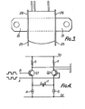
- the transducing head 10 has side plates 28 provided with one or more projections, two bearing the references 25 and 26 being shown in Figure 2.
- the projections 25 and 26 have tapered or rounded ends to guide the tape 1 and the body of the cassette 2 in the manner to be described.
- the upper surface of the lower part of the casing of the cassette 2 engages the lower edge 25B of the projection 25 and is held against it by the pressure of the spring 23. In this way the position of the cassette 2 in the direction normal to the paper as shown in Figure 1 is determined.
- the tape 1 is guided by the upper edge 25A of the projection 25 and the lower edge 26A of the projection 26, so that the position of the tape 1 over the head 10 is fixed by each of the end plates 28, and therefore the direction followed by the tape 1 over the head 10 is also determined.
- the positions of the plates 28 on the sides of the head 10 are accurately determined so that the tape 1 passes squarely over the recording gaps and the longitudinal direction of the tape 1 is held to be closely at right angles to the head in Figure 2 and these represent the manner in which the plates 28 are attached to the sides of the head 10.
- the alignment of the head 10 relative to the surface 11 is determined by the legs 30 on the plates 28 which are held against the surface 11 by the manner of attachment of the head 10 to the surface 11.
- the attachment itself is provided by a flexible metallic strip 31 which extends both sides of the head 10 and this strip is secured at its ends to the surface 11 using, for example, screws or rivets or pegs of plastics material.
- the resilience of the metallic strip 31 serves to press the legs 30 against the surface 11.
- the upper part of the casing of the cassette 2 is cut away to provide clearance for the upper tape guides 26 on the transducing head 10. It has been found that the upper tape guides 26 can be omitted from the plate 28 on one or both sides of the head 10 if the apparatus is such that the tape 1 is biassed towards the lower tape guides 25.
- a recording/playback arrangement includes a recording/playback head 1 one terminal of which is connected to the emitter electrode of a first NPN transistor 3.
- the emitter electrode of the transistor 2 is connected also to a controllable current source 4 and the collector electrode is provided with a load resistor 5 connected to a voltage supply.
- the base electrode of the transistor 2 is connected to a terminal for a waveform B when recording.
- the transistor 3 has its own emitter current source 6 corresponding to the current source 4 for the transistor 2 and a collector load resistor 7 corresponding to the collector load resistor 5 for the transistor 2.
- the base electrode of the transistor 3 is connected to a terminal for a waveform A when recording.
- the current sources 4 and 6 may be set at a first, relatively high level of a few tens of milliamperes, or at a second, relatively low level of several tens of microamperes.
- recording of a data signal is effected by driving the base electrode of the transistors 2 and 3 by means of the upright and inverted forms, B and A respectively, of the data signal and setting the respective current sources 4 and 6 at relatively high levels, referred to above.
- the current source settings are, in practice, not the same, for reasons set out below.
- the transistor 2 is therefore switched off when the transistor 3 is switched on, and vice-versa, with the result that the current from the current source 6 flows through the recording head 1 in one direction when the transistor 2 is switched on and the transistor 3 is switched off, and the current from the current source 4 flows through the recording head 1 in the opposite direction when the transistor 3 is switched on and the transistor 2 is switched off.
- An effect of arranging for the reversal of the magnetising current through the recording head 1 is that the peak-to-peak value of the drive voltage applied to the recording head 1 may exceed the supply voltage level to the collector loads of the transistors 2 and 3.
- the drive voltage applied to the recording head 1 may be of the order of 8 volts.
- the base electrodes of the transistors 2 and 3 are connected to fixed bias voltages to provide low noise level bias, the current source currents are set at the relatively low current levels referred to above, and the transistors 2 and 3 are operated as low-level common-base amplifiers with a differntial output signal available from collector to collector.
- the arrangement facilitates construction with the recording head 1 connected directly to the pins of an integrated circuit including the remaining components, an effect of which is to minimise the amount of external noise which will find its way into the output signal.
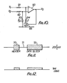
- the recording/playback arrangement of Figure 4 may be employed to effect the erasure of data by means of the recording head 1 by the use of a steady magnetising signal to effect saturation of the recording tape material.
- a consequence of d.c. erasure is that the recording tape material displays a magnetic bias after erasure.
- the technique, referred to above and illustrated by Figures 5 and 6, of recording with the current required by the current source 4 different from the current required by the current source 6, may be used to remove the magnetic bias to provide a recording centred about zero magnetic bias as illustrated by Figure 7.
- the technique is optional.
- Figure 11 represents a signal which may be the differential output signal of the recording/playback arrangement of Figure 4 in the playback mode.
- the differential output signal consists of a header signal 70 followed by a gap 71 which is itself followed by a data signal 72, the header signal 70 and the data signal 72 each being of about 200 millivolts amplitude.
- a circuit arrangement for obtaining a signal such as that represented by Figure 11 and for processing the signal includes a recording head 1, a differential amplifier 80, a coupling capacitor 81, a comparator 82, and a resistor 83 connected between the input ports of the comparator 82.
- the comparator 82 (Fig.9) includes a differential amplifier 90 having a resistor 91 in series with its non-inverting input port and a resistor 92 in series with its inverting input port.
- the inverting input port of the differential amplifier 90 is connected to the input of a current source 93 the output of which is connected to the negative power supply rail.
- the non-inverting input port of the differential amplifier 90 is connected to a current source 94 the output of which is connected to the negative power supply rail by way of a switch device 95.
- the switch device is either open or closed according to the output voltage of the differential amplifier 90 and has a control input connected to the output port of the differential amplifier 90 for the purpose.
- the resistor 83 maintains the input ports of the comparator 82 at the same d.c. potential, ensuring that the bias conditions do not influence the behaviour of the comparator 82. Also, the hysteresis of the comparator 82 is defined by the value of the input resistor 91 and the setting of the current source 94.
- Figure 12 represents a signal produced by the comparator 82 from the signal represented by Figure 11.
- the gap between the active portions of Figure 11 has been preserved while the active portions have been amplified to several volts compatible with digital logic circuitry.
- the gap between the active portions may be recognised by digital logic circuitry, which may include a central processing unit, as a synchronisation period, occurring immediately before a data block.
- the recording/playback device 131 includes a D flip-flop 134, the D-input terminal of which is connected to a first output terminal of the control device 130 and the clock-input terminal of which is connected to the clock-output terminal of the control device 130.
- the second recording/playback device 132 includes a D flip-flop 135, the D-input terminal of which is connected to the Q-output terminal of the flip-flop 134, and the CLOCK-input terminal of which is connected to the CLOCK-input terminal of the flip-flop 131.
- the third recording/playback device 133 includes a D flip-flop 136, the D-input terminal of which is connected to the Q-output terminal of the flip-flop 135, and the CLOCK-input terminal of which is connected to the CLOCK-input terminal of the flip-flop 135.
- the flip-flops 131, 132, 133 behave as a shift register, permitting a logic 1 condition originating at the control device 130 to be loaded into the first flip-flop 131 by the supply of a single clock pulse from the control device 130, the logic 1 condition to move to the second flip-flop 135 by the supply of a further clock pulse, and the logic 1 condition to move to the third flip-flop 136 by the supply of yet another clock pulse.
- the recording/ playback device 131 is switched on when the flip-flop 131 is set at logic 1
- the recording/playback device 132 is switched on when the flip-flop 135 is set at logic 1, and so on.
- the control device 130 is therefore able to select any one of the recording/ playback devices 131, 132, 133 by suplying a logic 1 condition accompanied by an apropriate number of clock pulses, Figure 14 illustrating the output required from the control device 130 to select the recording/ playback device 133.
- control device 130 may be used to select associated devices other than recording/ playback devices and that any number of associated devices may be accommodated by use of the technique described.
Landscapes
- Health & Medical Sciences (AREA)
- Chemical & Material Sciences (AREA)
- Medicinal Chemistry (AREA)
- Pharmacology & Pharmacy (AREA)
- Epidemiology (AREA)
- Life Sciences & Earth Sciences (AREA)
- Animal Behavior & Ethology (AREA)
- General Health & Medical Sciences (AREA)
- Public Health (AREA)
- Veterinary Medicine (AREA)
- Engineering & Computer Science (AREA)
- Manufacturing & Machinery (AREA)
- Recording Or Reproducing By Magnetic Means (AREA)
- Digital Magnetic Recording (AREA)
- Magnetic Heads (AREA)
Applications Claiming Priority (6)
| Application Number | Priority Date | Filing Date | Title |
|---|---|---|---|
| GB838314687A GB8314687D0 (en) | 1983-05-27 | 1983-05-27 | Tape recording and reproducing apparatus |
| GB8314688 | 1983-05-27 | ||
| GB838314688A GB8314688D0 (en) | 1983-05-27 | 1983-05-27 | Tape recording and reproducing apparatus |
| GB8314687 | 1983-07-28 | ||
| GB838320431A GB8320431D0 (en) | 1983-07-28 | 1983-07-28 | Magnetic tape recording and reproducing apparatus |
| GB8320431 | 1983-07-28 |
Publications (2)
| Publication Number | Publication Date |
|---|---|
| EP0132918A2 true EP0132918A2 (de) | 1985-02-13 |
| EP0132918A3 EP0132918A3 (de) | 1985-05-22 |
Family
ID=27262117
Family Applications (1)
| Application Number | Title | Priority Date | Filing Date |
|---|---|---|---|
| EP84303469A Withdrawn EP0132918A3 (de) | 1983-05-27 | 1984-05-22 | Magnetbandaufnahme- und Wiedergabegerät |
Country Status (6)
| Country | Link |
|---|---|
| EP (1) | EP0132918A3 (de) |
| KR (1) | KR850000108A (de) |
| AU (1) | AU2969984A (de) |
| ES (1) | ES532829A0 (de) |
| PT (1) | PT78650B (de) |
| WO (1) | WO1984004843A2 (de) |
Cited By (1)
| Publication number | Priority date | Publication date | Assignee | Title |
|---|---|---|---|---|
| EP0492705A1 (de) * | 1990-12-21 | 1992-07-01 | Koninklijke Philips Electronics N.V. | System mit einem Gerät und einer Kassette sowie Gerät und Kassette geeignet zum Gebrauch in einem derartigen System, und Magnetkopfeinheit geeignet zum Gebrauch in einem derartigen Gerät |
Family Cites Families (7)
| Publication number | Priority date | Publication date | Assignee | Title |
|---|---|---|---|---|
| US3504135A (en) * | 1966-11-29 | 1970-03-31 | Vm Corp | Magazine-type magnetic tape recorder having stepped tiltable drive shaft to engage tape reel flanges for two-speed two-direction drive |
| US3628797A (en) * | 1968-05-21 | 1971-12-21 | Itsuki Ban | Tape-cartridge-positioning apparatus |
| JPS519847Y2 (de) * | 1971-07-14 | 1976-03-16 | ||
| GB1432534A (en) * | 1973-04-18 | 1976-04-22 | Uher Werke Muenchen | Magnetic tape cassette recorder apparatus |
| US4055288A (en) * | 1975-03-31 | 1977-10-25 | Motorola, Inc. | Front drive cartridge-tape player system with fast forward and reverse modes |
| AU509932B2 (en) * | 1975-08-29 | 1980-05-29 | International Business Machines Corporation | A tape-containing cartridge |
| US4375071A (en) * | 1980-10-20 | 1983-02-22 | Amp Incorporated | Mounting means for magnetic read head |
-
1984
- 1984-05-22 EP EP84303469A patent/EP0132918A3/de not_active Withdrawn
- 1984-05-23 AU AU29699/84A patent/AU2969984A/en not_active Abandoned
- 1984-05-23 WO PCT/GB1984/000178 patent/WO1984004843A2/en not_active Ceased
- 1984-05-25 ES ES532829A patent/ES532829A0/es active Granted
- 1984-05-25 PT PT78650A patent/PT78650B/pt unknown
- 1984-05-28 KR KR1019840002919A patent/KR850000108A/ko not_active Withdrawn
Cited By (1)
| Publication number | Priority date | Publication date | Assignee | Title |
|---|---|---|---|---|
| EP0492705A1 (de) * | 1990-12-21 | 1992-07-01 | Koninklijke Philips Electronics N.V. | System mit einem Gerät und einer Kassette sowie Gerät und Kassette geeignet zum Gebrauch in einem derartigen System, und Magnetkopfeinheit geeignet zum Gebrauch in einem derartigen Gerät |
Also Published As
| Publication number | Publication date |
|---|---|
| ES8506920A1 (es) | 1985-08-01 |
| EP0132918A3 (de) | 1985-05-22 |
| PT78650B (en) | 1986-05-30 |
| PT78650A (pt) | 1985-01-16 |
| WO1984004843A3 (en) | 1984-12-20 |
| AU2969984A (en) | 1984-12-18 |
| ES532829A0 (es) | 1985-08-01 |
| WO1984004843A2 (en) | 1984-12-06 |
| KR850000108A (ko) | 1985-05-25 |
Similar Documents
| Publication | Publication Date | Title |
|---|---|---|
| US3914789A (en) | Manually operated magnetic card encoder | |
| DE69221944D1 (de) | Informationsaufzeichnungs/Wiedergabegerät | |
| EP0139163B1 (de) | Datenübertragungs-system mit mehreren Plattenantrieben | |
| US3766327A (en) | Tape cassette holding and positioning unit | |
| US3707707A (en) | Digital cassette magnetic tape recorder and reproducer | |
| ATA305388A (de) | Aufzeichnungs- und/oder wiedergabesystem und kassette fuer ein solches system | |
| EP0132918A2 (de) | Magnetbandaufnahme- und Wiedergabegerät | |
| MY113415A (en) | Magnetic recording and reproducing apparatus and cleaning cassette therefor | |
| US2916728A (en) | Magnetic recording and reading systems | |
| US6249397B1 (en) | Device for reading and writing data on magnetic recording layer of photo film | |
| GB1402394A (en) | Magnetic tape drive apparatus | |
| US5398146A (en) | Reset cassette with electromagnetic means for restoring the desired magnetization direction in a magnetoresistive head of a system for recording and/or reproducing signals | |
| JP3390050B2 (ja) | 情報信号記録及び/又は再生システム | |
| JPS5930309B2 (ja) | 磁気カ−ド処理装置 | |
| JPS59127209A (ja) | 磁気媒体読出し時の外来ノイズ除去方法 | |
| US3456858A (en) | Tape transport system | |
| JPS6379263A (ja) | 磁気テ−プスレツデイング機構 | |
| US3430005A (en) | Recording and reproducing heads with means for recording both magnetically and mechanically | |
| SU696526A1 (ru) | Устройство дл записи цифровой информации | |
| JPS60501481A (ja) | 磁気テ−プ記録再生機器 | |
| EP0572067A2 (de) | System zum Aufnehmen und/oder Wiedergeben von Signalen, sowie Rückstellkassette zum Gebrauch bei diesem System | |
| Wittrick | Magnetic Tape Recording Part II: Practical Aspects | |
| Best et al. | A computer-integrated rapid-access magnetic tape system with fixed address | |
| JPS60651A (ja) | 磁気デイスク装置 | |
| JPS58211305A (ja) | 磁気記録装置 |
Legal Events
| Date | Code | Title | Description |
|---|---|---|---|
| PUAI | Public reference made under article 153(3) epc to a published international application that has entered the european phase |
Free format text: ORIGINAL CODE: 0009012 |
|
| AK | Designated contracting states |
Designated state(s): AT BE CH DE FR GB IT LI LU NL SE |
|
| PUAL | Search report despatched |
Free format text: ORIGINAL CODE: 0009013 |
|
| AK | Designated contracting states |
Designated state(s): AT BE CH DE FR GB IT LI LU NL SE |
|
| 17P | Request for examination filed |
Effective date: 19850805 |
|
| RAP1 | Party data changed (applicant data changed or rights of an application transferred) |
Owner name: AMSTRAD CONSUMER ELECTRONICS PLC |
|
| 17Q | First examination report despatched |
Effective date: 19861203 |
|
| STAA | Information on the status of an ep patent application or granted ep patent |
Free format text: STATUS: THE APPLICATION IS DEEMED TO BE WITHDRAWN |
|
| 18D | Application deemed to be withdrawn |
Effective date: 19870414 |
|
| RIN1 | Information on inventor provided before grant (corrected) |
Inventor name: CHEESE, BENJAMIN JOHN Inventor name: SOUTHWARD, DAVID CONNER |