EP0132419B1 - Perfectionnements apportés aux raccords de dérivation obtenus par moulage d'un enrobage de matière de jonction, autour d'un insert rigide tubulaire notamment, et procédé de fabrication - Google Patents
Perfectionnements apportés aux raccords de dérivation obtenus par moulage d'un enrobage de matière de jonction, autour d'un insert rigide tubulaire notamment, et procédé de fabrication Download PDFInfo
- Publication number
- EP0132419B1 EP0132419B1 EP84401012A EP84401012A EP0132419B1 EP 0132419 B1 EP0132419 B1 EP 0132419B1 EP 84401012 A EP84401012 A EP 84401012A EP 84401012 A EP84401012 A EP 84401012A EP 0132419 B1 EP0132419 B1 EP 0132419B1
- Authority
- EP
- European Patent Office
- Prior art keywords
- insert
- flange
- pipe
- main
- main pipe
- Prior art date
- Legal status (The legal status is an assumption and is not a legal conclusion. Google has not performed a legal analysis and makes no representation as to the accuracy of the status listed.)
- Expired
Links
- 239000000463 material Substances 0.000 title claims description 29
- 238000000465 moulding Methods 0.000 title claims description 18
- 239000011248 coating agent Substances 0.000 title description 10
- 238000000576 coating method Methods 0.000 title description 10
- 238000004519 manufacturing process Methods 0.000 title description 5
- 238000000034 method Methods 0.000 claims description 15
- 238000010926 purge Methods 0.000 description 8
- 238000000605 extraction Methods 0.000 description 3
- 239000012530 fluid Substances 0.000 description 3
- 238000007789 sealing Methods 0.000 description 3
- 238000009434 installation Methods 0.000 description 2
- 230000008878 coupling Effects 0.000 description 1
- 238000010168 coupling process Methods 0.000 description 1
- 238000005859 coupling reaction Methods 0.000 description 1
- 230000008030 elimination Effects 0.000 description 1
- 238000003379 elimination reaction Methods 0.000 description 1
- 230000002787 reinforcement Effects 0.000 description 1
Images

Classifications
-
- F—MECHANICAL ENGINEERING; LIGHTING; HEATING; WEAPONS; BLASTING
- F16—ENGINEERING ELEMENTS AND UNITS; GENERAL MEASURES FOR PRODUCING AND MAINTAINING EFFECTIVE FUNCTIONING OF MACHINES OR INSTALLATIONS; THERMAL INSULATION IN GENERAL
- F16L—PIPES; JOINTS OR FITTINGS FOR PIPES; SUPPORTS FOR PIPES, CABLES OR PROTECTIVE TUBING; MEANS FOR THERMAL INSULATION IN GENERAL
- F16L41/00—Branching pipes; Joining pipes to walls
- F16L41/08—Joining pipes to walls or pipes, the joined pipe axis being perpendicular to the plane of a wall or to the axis of another pipe
-
- F—MECHANICAL ENGINEERING; LIGHTING; HEATING; WEAPONS; BLASTING
- F16—ENGINEERING ELEMENTS AND UNITS; GENERAL MEASURES FOR PRODUCING AND MAINTAINING EFFECTIVE FUNCTIONING OF MACHINES OR INSTALLATIONS; THERMAL INSULATION IN GENERAL
- F16L—PIPES; JOINTS OR FITTINGS FOR PIPES; SUPPORTS FOR PIPES, CABLES OR PROTECTIVE TUBING; MEANS FOR THERMAL INSULATION IN GENERAL
- F16L31/00—Arrangements for connecting hoses to one another or to flexible sleeves
- F16L31/02—Arrangements for connecting hoses to one another or to flexible sleeves for branching hoses
-
- Y—GENERAL TAGGING OF NEW TECHNOLOGICAL DEVELOPMENTS; GENERAL TAGGING OF CROSS-SECTIONAL TECHNOLOGIES SPANNING OVER SEVERAL SECTIONS OF THE IPC; TECHNICAL SUBJECTS COVERED BY FORMER USPC CROSS-REFERENCE ART COLLECTIONS [XRACs] AND DIGESTS
- Y10—TECHNICAL SUBJECTS COVERED BY FORMER USPC
- Y10S—TECHNICAL SUBJECTS COVERED BY FORMER USPC CROSS-REFERENCE ART COLLECTIONS [XRACs] AND DIGESTS
- Y10S285/00—Pipe joints or couplings
- Y10S285/915—Mastic
Definitions
- the present invention relates to improvements made to the branch fittings for flexible pipes, armored or not, sheathed or not, obtained by molding a coating of junction material, such as rubber, around a rigid tubular insert in particular. , and a method of manufacturing these fittings.
- the subject of the present invention is a branch connection for flexible pipes, armored or unarmoured, sheathed or not, of the type comprising a rigid tubular insert at least partially coated with a joining material, such as rubber, a main flexible pipe, provided with a bypass hole pierced at the chosen location, and a member to be connected to said main pipe,
- bypass connector is characterized in that the insert comprises at one end a first flared flange applied against the internal surface of a flanged boss also flared around the periphery of said orifice of the main pipe, in combination with a second external flange, and in that the insert forms an integral part of the bypass fitting.
- the insert in the case where the member to be connected to the main pipe is constituted by a secondary flexible pipe, the insert cooperates with a centering finger of the latter by compared to the main pipe.
- the other end of the insert is provided with notches which prevent the secondary pipe from being pulled out.
- the junction material molded around the main and secondary pipes del insert has the shape of a T, the transverse segment of which completely envelopes the corresponding portion of the main pipe, while the longitudinal segment of the T completely envelopes the corresponding portion of the secondary pipe, as well as the part of the insert lying between its flared end flange and its intermediate annular flange.
- the second collar of the isert is an annular coupling collar molded joint material formed around the other end of the insert.
- the present invention also relates to a method of manufacturing a branch connection for flexible pipes, armored or unarmoured, sheathed or not, of the type comprising the molding of a coating of junction material, such as rubber, around '' at least part of a rigid tubular insert included in the bypass fitting, and the prior placement of a rigid core supporting a main pipe, provided with a bypass hole drilled at the chosen location , as well as a secondary rigid core for supporting a member to be connected to said main pipe, which method is characterized in that the secondary core has a suitable tubular shape comprising at one end a first flared flange, intended to be applied against the internal surface of a flanged boss also flared around the periphery of said orifice of the main pipe, in combination with a second external flange, and in that, the molding of said joining material being carried out in known manner, only the main core is extracted once the molding is finished, while the secondary core is left in place as an insert forming an integral part of the molded branch fitting,
- the process for manufacturing a bypass fitting for flexible, armed or unarmoured, sheathed or unsheathed pipes, according to the invention has an indisputable advantage compared to the processes of the prior art also comprising the molding of a coating of material.
- the rigid insert 3a for supporting the secondary pipe 2 is left in place as a rigid lost core, or as a rigid tubular insert forming an integral part of the bypass connection, once the molding of the coating of junction material 4a is finished.
- This flared flange 5 holds the boss 9 of the main flexible pipe 1 securely in position, protecting it from any accidental take-off, which may become harmful for the sealing of the bypass fitting, if the take-off extends laterally.
- the insert 3a is provided with an annular collar 6 formed in an intermediate position on its outer surface, so as to allow the positioning of the terminal end of the secondary pipe 2.
- the upper end of the insert 3a, enveloped by the end of the secondary pipe 2, is advantageously provided with notches which prevent accidental tearing of this pipe 2; at the same time the notched end of the insert 3a securely holds the end of the secondary flexible pipe 2 in position, which is also protected from any accidental take-off and danger of loss of sealing.
- Said insert 3a cooperates with a centering finger (not shown) of the secondary flexible pipe 2 (which may a priori have any orientation) relative to the main flexible pipe 1.
- the coating 4a represented in FIG. 1 has the shape of a T, in particular of a Inverted T, whose transverse segment completely envelops the corresponding portion of the main pipe 1, while the longitudinal segment of this T completely envelopes the corresponding portion of the secondary pipe 2 as well as the part of the insert 3a between its flared collar 5 d end and its intermediate annular collar 6.
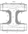
- the secondary rigid core 3b is left in place as a rigid lost core or as a rigid tubular insert forming an integral part of the bypass connection, once the molding of the covering of junction material 4b is completed, thus increasing the rigidity, tightness and service life of this branch connection: it is also obvious that it is thanks to the installation of this rigid insert 3b that "bridging" is made possible.
- the secondary core 3b is provided, in this case, at each end, with a flared flange 5 and 5 'respectively, which is applied against the internal surface of each of the bosses 9 and 9' with flared flange also formed on the periphery bypass holes 12 and 12 'drilled in the two main flexible pipes 1 and 1', respectively.
- the two flared flanges 5 and 5 ′ at the end of the insert 3b protect against protrusion the bosses 9 and 9 ′, respectively, which are applied against them and, thereby, contribute to the tightness of the fitting, preventing any contact between the armature S of the two main flexible pipes 1 and the and the fluid carried.
- the coating 4b shown in FIG. 2a the shape of a 1, in which each transverse segment completely envelops the corresponding portion of each of the main pipes 1 and 1 while the longitudinal segment of the 1 envelope completely completes said rigid tubular insert 3a.
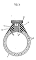
- the bypass fitting shown in Figure 3 refers to a purge bypass fitting.
- a tapped insert was used in this case, intended to receive a bleed screw in particular, which was connected to a main flexible pipe by molding a coating of junction material, after having previously set up the insert and a removable rigid rigid core for supporting this insert, assembled together by screwing in particular, and a rigid core also removable, for supporting the main flexible pipe, this removable main core also being assembled by screwing with the removable secondary core .
- the advantage of the process according to the present invention lies in the fact that the threaded insert is constituted by the secondary rigid core 3c (cf. FIG. 3) which is left in place, after molding, as a rigid tubular insert 3c intended to receive a bleed screw 10.
- This secondary core 3c is provided at its lower end with a flared flange 5 applying against the internal surface of the boss 9, with a flared flange also formed around the circumference of the bypass orifice 12 "drilled in the main pipe 1 , by protecting this boss 9 against an accidental take-off and therefore the armature 8 of the main pipe 1 against any contact with the transported fluid.
- the insert 3c is also provided with an annular collar 11 at the other end, so as to allow the attachment of the material molded junction 4c.
Landscapes
- Engineering & Computer Science (AREA)
- General Engineering & Computer Science (AREA)
- Mechanical Engineering (AREA)
- Protection Of Pipes Against Damage, Friction, And Corrosion (AREA)
- Injection Moulding Of Plastics Or The Like (AREA)
- Branch Pipes, Bends, And The Like (AREA)
- Lining Or Joining Of Plastics Or The Like (AREA)
Applications Claiming Priority (2)
| Application Number | Priority Date | Filing Date | Title |
|---|---|---|---|
| FR8311695A FR2549196B1 (fr) | 1983-07-13 | 1983-07-13 | Perfectionnements apportes aux raccords de derivation obtenus par moulage d'un enrobage de matiere de jonction, autour d'un insert rigide tubulaire notamment, et procede de fabrication |
| FR8311695 | 1983-07-13 |
Publications (3)
| Publication Number | Publication Date |
|---|---|
| EP0132419A2 EP0132419A2 (fr) | 1985-01-30 |
| EP0132419A3 EP0132419A3 (en) | 1985-03-06 |
| EP0132419B1 true EP0132419B1 (fr) | 1987-01-14 |
Family
ID=9290803
Family Applications (1)
| Application Number | Title | Priority Date | Filing Date |
|---|---|---|---|
| EP84401012A Expired EP0132419B1 (fr) | 1983-07-13 | 1984-05-17 | Perfectionnements apportés aux raccords de dérivation obtenus par moulage d'un enrobage de matière de jonction, autour d'un insert rigide tubulaire notamment, et procédé de fabrication |
Country Status (6)
| Country | Link |
|---|---|
| US (3) | US4650220A (enExample) |
| EP (1) | EP0132419B1 (enExample) |
| JP (1) | JPS6038128A (enExample) |
| DE (1) | DE3462068D1 (enExample) |
| ES (2) | ES293236Y (enExample) |
| FR (1) | FR2549196B1 (enExample) |
Families Citing this family (46)
| Publication number | Priority date | Publication date | Assignee | Title |
|---|---|---|---|---|
| FR2595437B2 (fr) * | 1981-06-01 | 1988-12-02 | Hutchinson | Raccord de derivation sur tuyau souple et son procede de pose |
| FR2549196B1 (fr) * | 1983-07-13 | 1985-12-27 | Hutchinson | Perfectionnements apportes aux raccords de derivation obtenus par moulage d'un enrobage de matiere de jonction, autour d'un insert rigide tubulaire notamment, et procede de fabrication |
| ES278800Y (es) * | 1984-04-13 | 1985-08-01 | Industrias Vulca, S.A. | Pieza de conexion multiple de circuitos para fluidos |
| US4708374A (en) * | 1984-07-30 | 1987-11-24 | Naco Industries, Inc. | Plastic Tee fitting |
| DE3430053C1 (de) * | 1984-08-16 | 1986-01-02 | Phoenix Ag, 2100 Hamburg | T-Schlauch |
| GB2187809B (en) * | 1984-12-15 | 1988-11-16 | Dunlop Ltd | Improvements in or relating to branched hose |
| DE3578449D1 (de) * | 1984-12-15 | 1990-08-02 | Dunlop Ltd | Schlauchabzweigungen. |
| GB2182408B (en) * | 1984-12-15 | 1988-11-16 | Dunlop Ltd | Improvements in or relating to branched hose |
| EP0185535B1 (en) * | 1984-12-15 | 1991-03-27 | Dunlop Limited | Improvements in or relating to branched hose |
| FR2596133B1 (fr) * | 1986-03-20 | 1988-08-12 | Caoutchouc Manuf Plastique | Procede de fabrication d'un dispositif de branchement et/ou de raccordement pour canalisations souples et dispositif de branchement et/ou de raccordement realise selon ce procede |
| GB8625679D0 (en) * | 1986-10-27 | 1986-11-26 | Ethicon Inc | Synthetic vascular grafts |
| FR2610073B1 (fr) * | 1987-01-23 | 1989-07-07 | Hutchinson | Procede de fabrication de dispositifs comme des raccords de derivation ou analogues sur des tubes ou tuyaux souples, en particulier a base de caoutchouc |
| US5302336A (en) * | 1987-04-16 | 1994-04-12 | Metzeler Automotive Profiles Gmbh | Method for producing molded hose branches from rubber and a hose produced by the method |
| DE8707246U1 (de) * | 1987-05-20 | 1987-07-30 | Continental Gummi-Werke Ag, 3000 Hannover | Schlauch, insbesondere Kraftfahrzeug-Kühlwasserschlauch |
| US5447341A (en) * | 1988-06-13 | 1995-09-05 | Metzeler Automotive Profiles Gmbh | Molder rubber hose branch |
| AU6818890A (en) * | 1989-12-19 | 1991-06-27 | Paul Neil James Barsby | Improved spigot for air-conditioning system |
| EP0468058A4 (en) * | 1990-02-15 | 1992-08-05 | Toa Grout Kogyo Kabushiki Kaisha | Method of water stopping in pipeline, construction of connecting portion of pipeline and water stop material |
| IT220447Z2 (it) * | 1990-06-08 | 1993-09-22 | Italiana Serrature Torino | Gruppo di collegamento per circuiti di circolazione del liquido di raffreddamento del motore di un veicolo |
| IT1240397B (it) * | 1990-07-12 | 1993-12-10 | Saiag Ind Spa | Raccordo di derivazione tra un tubo flessibile principale ed un tubo flessibile secondario. |
| US5335944A (en) * | 1991-03-25 | 1994-08-09 | Toyoda Gosei Co., Ltd. | Hose coupling structure |
| AT395900B (de) * | 1991-09-24 | 1993-03-25 | Geislinger Co Schwingungstechn | Kupplungsglied |
| US5356587A (en) * | 1991-10-14 | 1994-10-18 | Toyoda Gosei Co., Ltd. | Process for producing hose having connecting portion |
| FR2700195B1 (fr) * | 1993-01-07 | 1995-03-17 | Hutchinson | Raccord étanche d'un tube et d'un embout et son procédé de fabrication. |
| FR2735556B1 (fr) * | 1995-06-13 | 1997-08-22 | Hutchinson | Dispositif de raccordement renforce de conduits ou de tuyaux souples et/ou elastiquement deformables |
| US5721167A (en) * | 1997-02-10 | 1998-02-24 | Motorola, Inc. | Process for forming a semiconductor device and a static-random-access memory cell |
| US6315331B1 (en) * | 1998-03-13 | 2001-11-13 | The Gates Corporation | Molded hose joint assembly |
| DE19832375C1 (de) * | 1998-07-18 | 2000-06-08 | Geiger Technik Gmbh | Schlauch |
| US6199297B1 (en) * | 1999-02-01 | 2001-03-13 | Integrated Biosystems, Inc. | Lyophilization apparatus and methods |
| EP1390681A4 (en) | 2001-05-02 | 2007-12-26 | Aquatherm Ind Inc | APPLICATION FOR HEAT EXCHANGERS |
| US6913056B2 (en) * | 2002-01-31 | 2005-07-05 | Baxter International Inc. | Apparatus and method for connecting and disconnecting flexible tubing |
| BR0314116B1 (pt) * | 2002-09-12 | 2014-04-08 | Bj Services Co | Composição de isolamento térmico, método para melhorar o isolamento térmico de uma tubulação, e método para reduzir a velocidade de convecção de fluxo em um espaço anular |
| US7275543B2 (en) * | 2002-09-20 | 2007-10-02 | Baxter International Inc. | Coupler member for joining dissimilar materials |
| US20050011575A1 (en) * | 2003-07-17 | 2005-01-20 | Ingersoll-Rand Company | Method of manufacturing flow connectors and product produced thereby |
| US7722733B2 (en) * | 2004-03-29 | 2010-05-25 | Baxter International Inc. | Method for sterile connection of tubing |
| RU2293904C2 (ru) * | 2005-03-17 | 2007-02-20 | Владимир Николаевич Миланич | Фитинг |
| US20100187813A1 (en) * | 2009-01-23 | 2010-07-29 | Anders Richard M | Connector for Interconnecting A Lateral Pipe to A Main Pipe |
| GB0917158D0 (en) * | 2009-09-30 | 2009-11-11 | Epl Composite Solutions Ltd | Pipe joining device |
| US8220126B1 (en) | 2009-11-13 | 2012-07-17 | Mercury Plastics, Inc. | Barbed metal insert overmolding using crosslinked polymers |
| US8844111B1 (en) | 2009-11-13 | 2014-09-30 | Mercury Plastics, Inc. | Barbed metal insert overmolding using crosslinked polymers |
| US8540287B2 (en) * | 2011-02-09 | 2013-09-24 | Ats Products, Inc. | Saddle tap connection and installation device |
| US8936280B2 (en) | 2011-02-09 | 2015-01-20 | Ats Products, Inc. | Saddle tap connection and installation device |
| US20150308064A1 (en) * | 2014-04-27 | 2015-10-29 | David Doolaege | Water containment structure with finger ends |
| US10697713B2 (en) * | 2014-07-02 | 2020-06-30 | Trane International Inc. | Gas-fired tube swaged joint |
| IL280146B2 (en) | 2021-01-13 | 2024-01-01 | Rivulis Plastro Ltd | Drip irrigation lateral connector to feeder pipe |
| US12449082B2 (en) * | 2022-05-06 | 2025-10-21 | Fer-Pal Construction Ltd. | Apparatus and method for tapping a valve of a host pipe lined with a liner |
| DE102022209380A1 (de) * | 2022-09-08 | 2024-03-14 | Raumedic Ag | Biokompatible und/oder lebensmittelechte Schlauch-Baugruppe |
Family Cites Families (41)
| Publication number | Priority date | Publication date | Assignee | Title |
|---|---|---|---|---|
| US2137223A (en) * | 1938-02-03 | 1938-11-22 | Trimble Nurseryland Furniture | Fitting for collapsible tubs |
| US2180960A (en) * | 1938-07-26 | 1939-11-21 | Benjamin H Kennedy | Nipple structure |
| US2404766A (en) * | 1941-01-21 | 1946-07-23 | Firestone Tire & Rubber Co | Fuel tank |
| US2614827A (en) * | 1946-01-04 | 1952-10-21 | Clayton Mark & Co | Tubular joint |
| FR1160843A (fr) * | 1956-11-14 | 1958-08-11 | Dispositif perfectionné d'assemblage pour les prises de branchement sur les conduites de distribution de fluides | |
| US3129020A (en) * | 1961-04-10 | 1964-04-14 | Gen Motors Corp | Tray drainhose nipple |
| US3177528A (en) * | 1963-05-09 | 1965-04-13 | Archibald T Flower | Mold for applying electrically insulated coating to pipe fittings |
| US3232645A (en) * | 1963-10-21 | 1966-02-01 | John A Bucks | Tubular t insert |
| US3360283A (en) * | 1965-07-30 | 1967-12-26 | Spiral Pipe Corp | Pipe coupling |
| US3367358A (en) * | 1965-11-17 | 1968-02-06 | Philip B. Rentschler | Pipe juncture covering device and applying method |
| US3634167A (en) * | 1966-04-15 | 1972-01-11 | Keller Roehren Ag | Method of fabricating welded branched pipe connections from weldable thermoplastic materials |
| FR1577223A (enExample) * | 1967-07-21 | 1969-08-08 | ||
| FR2027029A1 (enExample) * | 1968-12-24 | 1970-09-25 | Mestre Barri Augustin | |
| US4043857A (en) * | 1969-10-21 | 1977-08-23 | Allied Chemical Corporation | Method of joining plastic pipe |
| US3654008A (en) * | 1970-07-15 | 1972-04-04 | Rogers Sales & Service Inc | Manufacture of a process of a plastic t-assembly |
| US3676579A (en) * | 1971-08-02 | 1972-07-11 | Westinghouse Electric Corp | Transformer lead insulator and method of making same |
| DE2147675A1 (de) * | 1971-09-24 | 1973-03-29 | Continental Gummi Werke Ag | Aus gummi oder gummiaehnlichen kunststoffen hergestellter schlauch oder schlauchkruemmer mit seitlichen abzweiganschluessen |
| DE2443824C2 (de) * | 1974-09-13 | 1976-10-14 | Phoenix Gummiwerke Ag | Verfahren und vorrichtung zum herstellen einer t-foermigen gummischlauchverzweigung |
| FR2291441A1 (fr) * | 1974-11-14 | 1976-06-11 | Kleber Colombes | Prise de derivation sur un tuyau en caoutchouc |
| US3992045A (en) * | 1975-02-03 | 1976-11-16 | Rev-O-Pak, Inc. | Means for coupling and sealing membrane carrying tube sections |
| US3989787A (en) * | 1975-07-28 | 1976-11-02 | Phillips Petroleum Company | Method of rotational molding a thermosetting article with a thermoplastic insert |
| US4018459A (en) * | 1975-07-30 | 1977-04-19 | Reed Irrigation Systems | Submain connector |
| JPS5341817A (en) * | 1976-09-28 | 1978-04-15 | Sekisui Chem Co Ltd | Method to connect pipe to pipe wall, tank wall and the like |
| GB1562184A (en) * | 1976-11-10 | 1980-03-05 | Wright R J | Pipe couplings |
| FR2393222A1 (fr) * | 1977-05-30 | 1978-12-29 | Hertfordshire Polymer Prod | Procede et appareillage de fabrication de raccords en matiere vulcanisable reliant un tube a une paroi ou un second tube |
| DE2834488A1 (de) * | 1978-08-07 | 1980-02-21 | Continental Gummi Werke Ag | Schlauch mit abzweigung |
| GB2038437B (en) * | 1978-12-27 | 1982-12-15 | Dunlop Ltd | Hose |
| US4327726A (en) * | 1979-08-15 | 1982-05-04 | Baxter Travenol Laboratories, Inc. | Connector member for dissimilar materials |
| DE2934098A1 (de) * | 1979-08-23 | 1981-03-26 | Georg Dipl.-Ing. 8000 München Steinbeisser | Fassonstueck fuer ebenengleiche rohrkreuzung in trittschallisolierung |
| US4345956A (en) * | 1980-04-16 | 1982-08-24 | Phillips Petroleum Company | Method for making a pipe connection or fitting |
| US4312687A (en) * | 1980-12-15 | 1982-01-26 | Chevron Research Company | Solar collector headers |
| FR2518699B2 (fr) * | 1981-03-30 | 1986-05-30 | Megias Bernard | Dispositif et procede de raccordement d'un conduit de piquage sur un conduit principal |
| FR2506892B1 (fr) * | 1981-06-01 | 1988-09-09 | Hutchinson Mapa | Raccord de derivation sur tuyau souple et son procede de pose |
| US4514244A (en) * | 1981-09-21 | 1985-04-30 | Nibco Inc. | Plastic pipe elements and methods for making same |
| DE3151640C2 (de) * | 1981-12-28 | 1985-09-05 | Continental Gummi-Werke Ag, 3000 Hannover | Verfahren zum Herstellen eines Gummi- oder Kunststoffschlauches mit textilen verstärkungseinlagen mit einem seitlich angesetzten Abzweigungsschlauch |
| DE3363578D1 (en) * | 1982-03-04 | 1986-06-26 | Avon Ind Polymers | Method of making branches in hoses |
| US4530525A (en) * | 1983-01-17 | 1985-07-23 | Hollister Incorporated | Access port forming device and method |
| DE3303519A1 (de) * | 1983-02-03 | 1984-08-09 | Hutchinson Gummiwarenfabrik Gmbh, 6800 Mannheim | Verfahren zum herstellen einer t-foermigen gummischlauchverzweigung mit gewebeverstaerkungseinlagen und eine t-foermige gummischlauchverzweigung |
| GB2138527B (en) * | 1983-04-18 | 1986-10-01 | Dunlop Ltd | Improvements in or relating to branched elastomeric hose |
| FR2549196B1 (fr) * | 1983-07-13 | 1985-12-27 | Hutchinson | Perfectionnements apportes aux raccords de derivation obtenus par moulage d'un enrobage de matiere de jonction, autour d'un insert rigide tubulaire notamment, et procede de fabrication |
| DE3430053C1 (de) * | 1984-08-16 | 1986-01-02 | Phoenix Ag, 2100 Hamburg | T-Schlauch |
-
1983
- 1983-07-13 FR FR8311695A patent/FR2549196B1/fr not_active Expired
-
1984
- 1984-05-08 US US06/608,209 patent/US4650220A/en not_active Expired - Lifetime
- 1984-05-17 DE DE8484401012T patent/DE3462068D1/de not_active Expired
- 1984-05-17 EP EP84401012A patent/EP0132419B1/fr not_active Expired
- 1984-05-22 ES ES1984293236U patent/ES293236Y/es not_active Expired
- 1984-07-03 JP JP59137855A patent/JPS6038128A/ja active Granted
-
1986
- 1986-06-25 ES ES556708A patent/ES8707593A1/es not_active Expired
- 1986-12-02 US US06/937,088 patent/US4740017A/en not_active Expired - Lifetime
-
1988
- 1988-05-13 US US07/195,376 patent/US4848801A/en not_active Expired - Fee Related
Also Published As
| Publication number | Publication date |
|---|---|
| JPH0153612B2 (enExample) | 1989-11-15 |
| DE3462068D1 (en) | 1987-02-19 |
| ES293236U (es) | 1987-01-16 |
| ES293236Y (es) | 1987-09-16 |
| US4740017A (en) | 1988-04-26 |
| EP0132419A2 (fr) | 1985-01-30 |
| ES8707593A1 (es) | 1987-08-01 |
| ES556708A0 (es) | 1987-08-01 |
| EP0132419A3 (en) | 1985-03-06 |
| FR2549196B1 (fr) | 1985-12-27 |
| JPS6038128A (ja) | 1985-02-27 |
| US4848801A (en) | 1989-07-18 |
| FR2549196A1 (fr) | 1985-01-18 |
| US4650220A (en) | 1987-03-17 |
Similar Documents
| Publication | Publication Date | Title |
|---|---|---|
| EP0132419A2 (fr) | Perfectionnements apportés aux raccords de dérivation obtenus par moulage d'un enrobage de matière de jonction, autour d'un insert rigide tubulaire notamment, et procédé de fabrication | |
| EP0944101B1 (fr) | Dispositif passe-barre et traversée électrique de paroi | |
| EP0606028B1 (fr) | Raccord étanche d'un tube et d'un embout et son procédé de fabrication | |
| EP1064489B1 (fr) | Raccord encliquetable pour tuyaux | |
| EP3014160B1 (fr) | Connecteur fluidique avec serrage de tube intégré | |
| EP0360634B1 (fr) | Dispositif de jonction entre un raccord souple et un embout tubulaire rigide d'un circuit sous pression | |
| FR2593885A1 (fr) | Raccord etanche pour conduit a surface externe ondulee | |
| EP0170545A1 (fr) | Connecteur de dérivation isolé pour câbles électriques | |
| EP0277058B1 (fr) | Procédé de fabrication de dispositifs comme des raccords de dérivation ou analogues sur des tubes ou tuyaux souples, en particulier à base de caoutchouc | |
| FR2679313A1 (fr) | Dispositif de serrage etanche pour le serrage d'un tube flexible monte a force a l'interieur d'un raccord tubulaire. | |
| FR2557255A1 (fr) | Procede pour realiser un element de coupla ge destine a assurer le raccordement entre une conduite principale et une conduite de derivation | |
| EP0335772B1 (fr) | Embout de câblage | |
| EP0253712B1 (fr) | Dispositif de fixation l'une à l'autre de deux parties cylindriques, notamment d'un tuyau sur un embout et son procédé de montage | |
| FR2742857A1 (fr) | Plaque collectrice pour echangeur de chaleur | |
| WO2014106609A1 (fr) | Raccord pour circuit de fibres optiques et procede de connexion d'un tel circuit a un tel raccord | |
| EP0617217A1 (fr) | Conduit, en particulier pour véhicule automobile | |
| FR2576465A1 (fr) | Joint de cables electriques, notamment pour haute tension | |
| FR2466887A1 (fr) | Bouchon d'etancheite pour canalisation de cable electrique et procede s'y rapportant | |
| EP1144901B1 (fr) | Dispositif de branchement d'une canalisation de derivation sur une canalisation de transport de fluide | |
| EP0350394B1 (fr) | Système d'évacuation d'eaux pluviales | |
| EP0683556B1 (fr) | Pièce de liaison électrique d'un manchon protecteur avec une extrémité d'un écran semi-conducteur d'un câble électrique | |
| FR2543369A2 (fr) | Dispositif d'etancheite pour connecteur electrique | |
| FR2595437A2 (fr) | Raccord de derivation sur tuyau souple et son procede de pose | |
| FR3048309B1 (fr) | Dispositif de raccordement electrique entre un fil et un element conducteur | |
| FR2668240A1 (fr) | Dispositif de raccordement de deux tuyaux de part et d'autre d'un element de cloison. |
Legal Events
| Date | Code | Title | Description |
|---|---|---|---|
| PUAI | Public reference made under article 153(3) epc to a published international application that has entered the european phase |
Free format text: ORIGINAL CODE: 0009012 |
|
| PUAL | Search report despatched |
Free format text: ORIGINAL CODE: 0009013 |
|
| AK | Designated contracting states |
Designated state(s): DE GB IT NL SE |
|
| AK | Designated contracting states |
Designated state(s): DE GB IT NL SE |
|
| 17P | Request for examination filed |
Effective date: 19850208 |
|
| 17Q | First examination report despatched |
Effective date: 19860522 |
|
| ITF | It: translation for a ep patent filed | ||
| GRAA | (expected) grant |
Free format text: ORIGINAL CODE: 0009210 |
|
| AK | Designated contracting states |
Kind code of ref document: B1 Designated state(s): DE GB IT NL SE |
|
| REF | Corresponds to: |
Ref document number: 3462068 Country of ref document: DE Date of ref document: 19870219 |
|
| PLBI | Opposition filed |
Free format text: ORIGINAL CODE: 0009260 |
|
| 26 | Opposition filed |
Opponent name: PHOENIX AKTIENGESELLSCHAFT Effective date: 19871009 |
|
| NLR1 | Nl: opposition has been filed with the epo |
Opponent name: PHOENIX AKTIENGESELLSCHAFT |
|
| PLBN | Opposition rejected |
Free format text: ORIGINAL CODE: 0009273 |
|
| STAA | Information on the status of an ep patent application or granted ep patent |
Free format text: STATUS: OPPOSITION REJECTED |
|
| 27O | Opposition rejected |
Effective date: 19891124 |
|
| NLR2 | Nl: decision of opposition | ||
| ITTA | It: last paid annual fee | ||
| EAL | Se: european patent in force in sweden |
Ref document number: 84401012.4 |
|
| PGFP | Annual fee paid to national office [announced via postgrant information from national office to epo] |
Ref country code: SE Payment date: 19990325 Year of fee payment: 16 |
|
| PGFP | Annual fee paid to national office [announced via postgrant information from national office to epo] |
Ref country code: NL Payment date: 19990427 Year of fee payment: 16 |
|
| PGFP | Annual fee paid to national office [announced via postgrant information from national office to epo] |
Ref country code: GB Payment date: 19990504 Year of fee payment: 16 |
|
| PGFP | Annual fee paid to national office [announced via postgrant information from national office to epo] |
Ref country code: DE Payment date: 19990526 Year of fee payment: 16 |
|
| PG25 | Lapsed in a contracting state [announced via postgrant information from national office to epo] |
Ref country code: GB Free format text: LAPSE BECAUSE OF NON-PAYMENT OF DUE FEES Effective date: 20000517 |
|
| PG25 | Lapsed in a contracting state [announced via postgrant information from national office to epo] |
Ref country code: SE Free format text: LAPSE BECAUSE OF NON-PAYMENT OF DUE FEES Effective date: 20000518 |
|
| PG25 | Lapsed in a contracting state [announced via postgrant information from national office to epo] |
Ref country code: NL Free format text: LAPSE BECAUSE OF NON-PAYMENT OF DUE FEES Effective date: 20001201 |
|
| GBPC | Gb: european patent ceased through non-payment of renewal fee |
Effective date: 20000517 |
|
| EUG | Se: european patent has lapsed |
Ref document number: 84401012.4 |
|
| NLV4 | Nl: lapsed or anulled due to non-payment of the annual fee |
Effective date: 20001201 |
|
| PG25 | Lapsed in a contracting state [announced via postgrant information from national office to epo] |
Ref country code: DE Free format text: LAPSE BECAUSE OF NON-PAYMENT OF DUE FEES Effective date: 20010301 |