EP0132189A1 - Stopper with retractable pouring spout - Google Patents
Stopper with retractable pouring spout Download PDFInfo
- Publication number
- EP0132189A1 EP0132189A1 EP84401442A EP84401442A EP0132189A1 EP 0132189 A1 EP0132189 A1 EP 0132189A1 EP 84401442 A EP84401442 A EP 84401442A EP 84401442 A EP84401442 A EP 84401442A EP 0132189 A1 EP0132189 A1 EP 0132189A1
- Authority
- EP
- European Patent Office
- Prior art keywords
- spout
- cover
- orifice
- capsule body
- pipe
- Prior art date
- Legal status (The legal status is an assumption and is not a legal conclusion. Google has not performed a legal analysis and makes no representation as to the accuracy of the status listed.)
- Granted
Links
Images

Classifications
-
- B—PERFORMING OPERATIONS; TRANSPORTING
- B65—CONVEYING; PACKING; STORING; HANDLING THIN OR FILAMENTARY MATERIAL
- B65D—CONTAINERS FOR STORAGE OR TRANSPORT OF ARTICLES OR MATERIALS, e.g. BAGS, BARRELS, BOTTLES, BOXES, CANS, CARTONS, CRATES, DRUMS, JARS, TANKS, HOPPERS, FORWARDING CONTAINERS; ACCESSORIES, CLOSURES, OR FITTINGS THEREFOR; PACKAGING ELEMENTS; PACKAGES
- B65D47/00—Closures with filling and discharging, or with discharging, devices
- B65D47/04—Closures with discharging devices other than pumps
- B65D47/06—Closures with discharging devices other than pumps with pouring spouts or tubes; with discharge nozzles or passages
- B65D47/16—Closures with discharging devices other than pumps with pouring spouts or tubes; with discharge nozzles or passages with closures operating automatically when spout is immersed in discharged liquid
-
- B—PERFORMING OPERATIONS; TRANSPORTING
- B65—CONVEYING; PACKING; STORING; HANDLING THIN OR FILAMENTARY MATERIAL
- B65D—CONTAINERS FOR STORAGE OR TRANSPORT OF ARTICLES OR MATERIALS, e.g. BAGS, BARRELS, BOTTLES, BOXES, CANS, CARTONS, CRATES, DRUMS, JARS, TANKS, HOPPERS, FORWARDING CONTAINERS; ACCESSORIES, CLOSURES, OR FITTINGS THEREFOR; PACKAGING ELEMENTS; PACKAGES
- B65D47/00—Closures with filling and discharging, or with discharging, devices
- B65D47/04—Closures with discharging devices other than pumps
- B65D47/20—Closures with discharging devices other than pumps comprising hand-operated members for controlling discharge
- B65D47/2012—Closures with discharging devices other than pumps comprising hand-operated members for controlling discharge formed by a rigid spout outlet and an overcap, the spout outlet being either pushed into alignment with, or pushed through an opening in the overcap, upon rotation of the latter
Definitions
- the present invention relates to a self-eclipsing spout closure cap for containers, such as plastic, glass or metal tubes and vials.
- plastic tubes are fitted with closure systems, such as screw caps separating from the tube, tamper-evident capsules with a vertical tip to be cut and possibly re-sealable and service capsules.
- closure systems such as screw caps separating from the tube, tamper-evident capsules with a vertical tip to be cut and possibly re-sealable and service capsules.
- service capsule designates the closure systems which remain integral with the body of the tube and which require a minimum of handling.
- Service capsules of this type are, for example, articulated lever capsules, capsules with hinged cover and capsules with a communication hole offset on the top of the capsule.
- the capsule body 1 shown in Figures 1 and 2 is cylindrical in shape and has a central groove 2 which passes diametrically through the upper plate of said capsule body and has a rectangular section. One of the ends 3 of the tray groove is closed. Given the cylindrical shape of the capsule body, the central groove has substantially the shape of a "U"
- the capsule body also has an orifice 4 to ensure the exit of the product contained in the container provided with the closure capsule.
- This orifice 4 is located in the center of the body of the capsule 1 and is advantageously provided with a sealing ring 5.
- the capsule body 1 also comprises means for fixing or hooking the cover; these means may for example be constituted by a circular groove 6 preferably located at the bottom of the capsule body.
- the capsule body 1 of the closure system according to the invention is adapted to the container to be closed; for example, it may consist of the ring of a tube 7, as shown by way of illustration in the accompanying drawings. It can also be any capsule for a glass vial or metal container, the capsule being fixed to said container whether or not in solidarity.
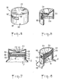
- the pouring spout which constitutes another element of the closure cap according to the invention is shown in FIGS. 3 and 4. It has the shape of a rectangular parallelepiped 8 of which the two ends 9 and 10 are rounded; in the remainder of this description, these ends 9 and 10 will be respectively called front 9 and rear 10 of the pouring spout.
- This parallelepiped has dimensions such that it can be housed in the groove 2 of the capsule body, the lateral faces of said parallelepiped being provided with guide means II, for example guide rods.
- the spout has in its internal part an outlet pipe 12 and 13 of the product contained in the container provided with the closure system of the invention.
- This pipe consists of two portions, one 12 passing longitudinally through the parallelepiped from the front 9 of the pouring spout to the second portion 13, which is perpendicular to it, is located towards the rear 10 of the spout and leads to the underside of said spout.
- the rear 10 of the spout is advantageously hollowed out so that it acts as a leaf spring 14.
- the pouring spout On its upper face, the pouring spout has a vertical lug 15. The relative position of the vertical lug 15 and the orifice of the portion 13 will be defined below with regard to the operation of the closure system.
- the cover 16 the third element of the closure system of the invention, is shown in Figures 5 and 6. It consists of a central plate 17 and a cylindrical skirt 18, which has a window 19 adapted to allow the outlet of the spout when in use.
- This window can be provided with a tear-away tamper-evident tab.
- the height of this window is therefore substantially greater than the height of the spout and its width preferably corresponds approximately to a quarter of the circumference of the cover.
- the skirt 18 also includes an opening 20 at its lower part; this opening 20 which is suitable for mounting the cover, must not be located below the window 19.
- the cover has in its inner part hooking means 23 constituted for example by a projection having suitable characteristics to be housed in the groove 6 of the capsule body and a stud coming closely to marry the front opening of the spout.
- the inner part of the central plate advantageously has a convex shape and comprises, in its middle, a hemispherical part 22 directed towards the inside of the cover, and, in the front part, a guide ramp 21, having a specific shape, which cooperates with the vertical lug of the pouring spout for moving it.
- front part denotes the part of the central plate which is above the skirt portion 18 where the window 19 is located.
- the guide ramp 21, integral with the central plate 17, has a specific shape adapted to allow the outlet and re-entry of the pouring spout 8 through the window 19 of the cover, by rotation of the latter, for example by rotation of a quarter of turn.
- This ramp 21 extends from the periphery of the cover towards the center of the latter and its length is a function of the width of the window.
- the shape of the ramp is defined below by its function of guiding the pouring spout, which first ensures the disengagement of the pouring spout and then the displacement thereof towards the outside when the closure system is opened. .
- This shape is such that at the start of rotation of the cover, the spout remains stationary in the central groove 2 until the front 9 of the spout is fully visible through the window 19; then, the shape of the guide ramp is suitable for allowing the outlet of the pouring spout through the window 19 until the orifice of the pipe 13 faces the orifice 4, the vertical lug 15 then being advantageously at the periphery of the cover 16.
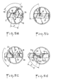
- FIG. 9 A preferred embodiment of the guide ramp 21 is shown in Figure 9 which illustrates the operation of the closure system of the invention, by rotating the cover a quarter turn.
- Figures 9a and 9d show the closure system respectively in the “closing” and “opening” positions
- Figures 9b and 9c show intermediate positions between opening and closing.
- the distance between the vertical lug 15 and the orifice of the pipe 13 and the distance between the two ends of the ramp 21 are substantially equal to the internal radius " r "of the cover 16.
- the vertical lug 15, the orifice of the pipe 13 and the side 19 ′ of the window are aligned.
- the guide ramp 21 shown in Figure 9 consists of two parts 21a and 21b.
- the part 21a of the ramp cooperates with the vertical lug 15 to keep the spout stationary until the front 9 thereof has become completely visible through the window 19 during the rotation of the cover 16.
- the shape of this part 21a is substantially that of an arc of a circle whose center is the ori fice 4 and the radius is the distance between the orifice 4 and the vertical lug 15, when the spout is entirely in the groove 2, that is to say in the closed position ( Figure 9a).
- the part 21b of the ramp cooperates with the vertical lug 15 to ensure the translational output of the pouring spout 8 from the groove 2.
- the preferred form of this part 21b shown in the figure 9 is an arc of radius "r" which passes through the center of the capsule body.
- the pouring spout 8 is positioned in the groove 2 of the capsule body; the cover 16 in the closed position is snapped onto the capsule body 1.
- the opening 20 provided on the skirt of the cover allows a mechanical finger to hold the pouring spout in the groove 2 before the cover is put in place; by removing the mechanical finger, the movable spout is trapped in the cover.
- Pressure is obtained from the movable spout on the inner wall of the cover thanks to the rear leaf spring 14. A slight clearance between the ramp and the axis allows the pressure to vary.
- the mouth of the spout is housed in the stud located in the inner side wall of the cover.
- the spout is in the use position outside the cover by unscrewing movement of a quarter of a turn of the cover. By a quarter-turn screwing movement, the spout enters the inside of the cover. The spout is driven by the rotation of the cover, the vertical lug 15 being housed in the guide rail of the cover.
- the central hemispherical part of the cover makes it possible to maintain the necessary sealing pressures during movements (opening / closing).
- the rear 10 of the spout is hollowed out and acts as a leaf spring 14; we obtain, thanks to this blade, a pressure of the movable spout on the inner wall of the cover, a slight clearance between the ramp and the lug allowing the pressure variation.
- the various elements of the closure system according to the invention can be made of the same material, for example in the case of a plastic tube, or of different materials such as, for example, a metal. It is important that the material of the spout is inert with respect to the product contained in the container. These elements are advantageously obtained by molding, injection or machining.
- the closure system allows the automatic outlet and re-entry of the spout, which are done horizontally.
- the spout substantially exceeds the outside diameter of the tube, preventing any leakage on the packaging.
- the pouring spout inside the lid is protected from any external contamination.
- the friction of the spout on the wall ensures self-cleaning thereof, thus making it possible, for example, to remove the sand in the case of containers containing solar products.
Abstract
Description
La présente invention concerne une capsule de bouchage à bec verseur auto-éclipsable pour récipients, tels que tubes et flacons en plastique, verre ou métal.The present invention relates to a self-eclipsing spout closure cap for containers, such as plastic, glass or metal tubes and vials.
En général, les tubes plastiques sont équipés de systèmes de bouchage, tels que des capsules à vis se désolidarisant du tube, des capsules inviolables à embout vertical à couper et éventuellement rebouchable et des capsules service.In general, plastic tubes are fitted with closure systems, such as screw caps separating from the tube, tamper-evident capsules with a vertical tip to be cut and possibly re-sealable and service capsules.
Dans la présente description, on désigne par "capsule service" les systèmes de bouchage restant solidaires du corps du tube et exigeant un minimum de manipulations. Les capsules service de ce type sont par exemple les capsules à levier articulable, les capsules à couvercle rabattable et les capsules à trou de communication décalé sur le dessus de la capsule.In the present description, the term "service capsule" designates the closure systems which remain integral with the body of the tube and which require a minimum of handling. Service capsules of this type are, for example, articulated lever capsules, capsules with hinged cover and capsules with a communication hole offset on the top of the capsule.
On a maintenant trouvé un nouveau système de bouchage de type capsule service permettant la sortie et la rentrée automatique d'un bec verseur.We have now found a new closure system of the capsule service type allowing the automatic exit and re-entry of a pouring spout.
La capsule de bouchage selon l'invention comprend trois parties :
- - un corps de capsule cylindrique dont le plateau supérieur comporte une rainure centrale, l'une des extrémités de la rainure étant obturée ;
- - un bec verseur muni d'un ergot vertical, ledit bec verseur étant mobile dans la rainure centrale ;
- - un couvercle tournant muni d'une rampe de guidage de forme spécifique, coopérant avec l'ergot vertical du bec verseur lors de la rotation dudit couvercle.
- - A cylindrical capsule body, the upper plate of which has a central groove, one end of the groove being closed;
- - a pouring spout provided with a vertical lug, said pouring spout being movable in the central groove;
- - A revolving cover provided with a guide ramp of specific shape, cooperating with the vertical lug of the pouring spout during the rotation of said cover.
La capsule de bouchage selon l'invention va être maintenant décrite en détail en référence aux dessins annexés sur lesquels :
- - la figure 1 représente le corps de capsule cylindrique
- - la figure 2 est une coupe axiale de ladite capsule
- - la figure 3 représente le bec verseur
- - la figure 4 est une coupe axiale partielle du bec verseur
- - les figures 5 et 6 représentent le couvercle, la figure 6 étant une coupe du couvercle avec arraché.
- - les figures 7 et 8 représentent la capsule de bouchage de l'invention montée sur un tube,
- - la figure 9 illustre la cinématique de fonctionnement de la capsule selon l'invention.
- - Figure 1 shows the cylindrical capsule body
- - Figure 2 is an axial section of said capsule
- - Figure 3 shows the spout
- - Figure 4 is a partial axial section of the spout
- - Figures 5 and 6 show the cover, Figure 6 being a section of the cover with broken away.
- FIGS. 7 and 8 show the closure cap of the invention mounted on a tube,
- - Figure 9 illustrates the kinematics of operation of the capsule according to the invention.
Le corps de capsule 1 représenté sur les figures 1 et 2 est de forme cylindrique et comporte une rainure centrale 2 qui traverse diamétralement le plateau supérieur dudit corps de capsule et présente une section rectangulaire. L'une des extrémités 3 de la rainure du plateau est obturée. Etant donné la forme cylindrique du corps de capsule, la rainure centrale a sensiblement la forme d'un "U"The
Le corps de capsule comporte également un orifice 4 pour assurer la sortie du produit contenu dans le récipient muni de la capsule de bouchage.The capsule body also has an
Cet orifice 4 est situé au centre du corps de la capsule 1 et est avantageusement muni d'une couronne d'étanchéité 5. Le corps de capsule 1 comporte aussi des moyens de fixation ou d'accrochage du couvercle ; ces moyens peuvent être par exemple constitués par une cannelure circulaire 6 située de préférence à la partie inférieure du corps de capsule.This
Le corps de capsule 1 du système de bouchage selon l'invention est adapté au récipient à boucher ; par exemple, il peut être constitué par la bague d'un tube 7, telle que représentée à titre illustratif sur les dessins annexés. Il peut être également une capsule quelconque pour flacon de verre ou récipient en métal, la capsule étant fixée audit récipient de façon solidaire ou non.The
Le bec verseur qui constitue un autre élément de la capsule de bouchage selon l'invention est représenté sur les figures 3 et 4. Il a la forme d'un parallélépipède rectangle 8 dont les deux extrémités 9 et 10 sont arrondies ; dans la suite de la présente description, ces extrémités 9 et 10 seront respectivement dénommées avant 9 et arrière 10 du bec verseur. Ce parallélépipède a des dimensions telles qu'il peut se loger dans la rainure 2 du corps de capsule, les faces latérales dudit parallélépipède étant munies de moyens de guidage Il, par exemple de joncs de guidage. Le bec verseur comporte dans sa partie interne une canalisation de sortie 12 et 13 du produit contenu dans le récipient muni du système de bouchage de l'invention.The pouring spout which constitutes another element of the closure cap according to the invention is shown in FIGS. 3 and 4. It has the shape of a
Cette canalisation est constituée de deux portions, l'une 12 traversant longitudinalement le parallélépipède de l'avant 9 du bec verseur jusqu'à la seconde portion 13, qui lui est perpendiculaire, est située vers l'arrière 10 du bec et débouche sur la face inférieure dudit bec. L'arrière 10 du bec est avantageusement évidée de sorte qu'elle fait office de lame-ressort 14. Sur sa face supérieure, le bec verseur a un ergot vertical 15. La position relative de l'ergot vertical 15 et de l'orifice de la portion 13 sera définie ci-après au sujet du fonctionnement du système de bouchage.This pipe consists of two portions, one 12 passing longitudinally through the parallelepiped from the front 9 of the pouring spout to the
Le couvercle 16, troisième élément du système de bouchage de l'invention, est représenté sur les figures 5 et 6. Il est constitué d'un plateau central 17 et d'une jupe cylindrique 18, laquelle comporte une fenêtre 19 adaptée pour permettre la sortie du bec verseur lors de son utilisation. Cette fenêtre peut être munie d'une languette d'inviolabilité arrachable. La hauteur de cette fenêtre est donc sensiblement supérieure à la hauteur du bec verseur et sa largeur correspond de préférence approximativement à un quart de la circonférence du couvercle. La jupe 18 comprend également une ouverture 20 à sa partie inférieure ; cette ouverture 20 qui convient pour le montage du couvercle, ne doit pas être située au-dessous de la fenêtre 19.The
Le couvercle comporte dans sa partie intérieure des moyens d'accorchage 23 constitués par exemple par une saillie ayant des caractéristiques appropriées pour se loger dans la cannelure 6 du corps de capsule et un plot venant épouser étroitement l'ouverture avant du bec verseur.The cover has in its inner part hooking means 23 constituted for example by a projection having suitable characteristics to be housed in the
La partie intérieure du plateau central a avantageusement une forme convexe et comporte, en son milieu, une partie hémisphérique 22 dirigée vers l'intérieur du couvercle, et, dans la partie avant, une rampe de guidage 21, ayant une forme spécifique, laquelle coopère avec l'ergot vertical du bec verseur pour le déplacement de celui-ci.The inner part of the central plate advantageously has a convex shape and comprises, in its middle, a
Par partie avant, on désigne la partie du plateau central qui est au-dessus de la portion de jupe 18 où se trouve la fenêtre 19.The term “front part” denotes the part of the central plate which is above the
L'ensemble du système de bouchage selon l'invention monté sur un tube est représenté par les figures 7 et 8,. sur lesquelles les références utilisées sont les mêmes que celles utilisées précédemment.The entire closure system according to the invention mounted on a tube is shown in Figures 7 and 8 ,. on which the references used are the same as those used previously.
La rampe de guidage 21, solidaire du plateau central 17, a une forme spécifique adaptée pour permettre la sortie et la rentrée du bec verseur 8 par la fenêtre 19 du couvercle, par rotation de celui-ci, par exemple par rotation d'un quart de tour. Cette rampe 21 s'étend de la périphérie du couvercle vers le centre de celui-ci et sa longueur est fonction de la largeur de la fenêtre. La forme de la rampe est définie ci-après par sa fonction de guidage du bec verseur, laquelle assure d'abord le dégagement du bec verseur et ensuite le déplacement de celui-ci vers l'extérieur lors de l'ouverture du système de bouchage. Cette forme est telle qu'au début de la rotation du couvercle, le bec verseur reste immobile dans la rainure centrale 2 jusqu'à ce que l'avant 9 du bec verseur soit entièrement visible par la fenêtre 19 ; ensuite, la forme de la rampe de guidage est appropriée pour permettre la sortie du bec verseur par la fenêtre 19 jusqu'à ce que l'orifice de la canalisation 13 soit face à l'orifice 4, l'ergot vertical 15 étant alors avantageusement à la périphérie du couvercle 16.The
Un mode préféré de réalisation de la rampe de guidage 21 est représenté sur la figure 9 qui illustre le fonctionnement du système de bouchage de l'invention, par rotation d'un quart de tour du couvercle.A preferred embodiment of the
Les figures 9 a et 9 d représentent le système de bouchage respectivement dans les positions "fermeture" et "ouverture", les figures 9 b et 9 c représentent des positions intermédiaires entre l'ouverture et la fermeture.Figures 9a and 9d show the closure system respectively in the "closing" and "opening" positions, Figures 9b and 9c show intermediate positions between opening and closing.
Dans ce mode de réalisation préféré, donné à titre d'exemple non limitatif, la distance entre l'ergot vertical 15 et l'orifice de la canalisation 13 et la distance entre les deux extrémités de la rampe 21 sont sensiblement égales au rayon intérieur "r" du couvercle 16. Dans la position fermeture (figure 9a), l'ergot vertical 15, l'orifice de la canalisation 13 et le côté 19' de la fenêtre sont alignés.In this preferred embodiment, given by way of nonlimiting example, the distance between the
La rampe de guidage 21 représente sur la figure 9 est constitué de deux parties 21a et 21b. La partie 21a de la rampe coopère avec l'ergot vertical 15 pour maintenir le bec verseur immobile jusqu'à ce que l'avant 9 de celui-ci soit devenu complètement visible par la fenêtre 19 lors de la rotation du couvercle 16. La forme de cette partie 21a est sensiblement celle d'un arc de cercle dont le centre est l'orifice 4 et le rayon est la distance entre l'orifice 4 et l'ergot vertical 15, lorsque le bec verseur est entièrement dans la rainure 2, c'est-à-dire en position fermeture (figure 9a). Ensuite, lorsqu'on poursuit la rotation du couvercle, la partie 21b de la rampe coopère avec l'ergot vertical 15 pour assurer la sortie par translation du bec verseur 8 de la rainure 2. La forme préférée de cette partie 21b représentée sur la figure 9 est un arc de cercle de rayon "r" qui passe par le centre du corps de capsule.The
Pour l'assemblage des trois éléments du système de bouchage de l'invention, le bec verseur 8 est positionné dans la rainure 2 du corps de capsule ; le couvercle 16 en position fermeture est encliqueté sur le corps de capsule 1. L'ouverture 20 prévue sur la jupe du couvercle permet à un doigt mécanique de maintenir le bec verseur dans la rainure 2 avant la mise en place du couvercle ; en retirant le doigt mécanique, le bec mobile est emprisonné dans le couvercle. On obtient une pression du bec mobile sur la paroi intérieure du couvercle grâce à la lame-ressort arrière 14. Un léger jeu entre la rampe et l'axe permet la variation de pression. L'orifice du bec vient se loger dans le plot situé dans la paroi latérale intérieure du couvercle.For the assembly of the three elements of the closure system of the invention, the pouring
Dans le mode de réalisation de la figure 9, le bec verseur est en position d'utilisation hors du couvercle par mouvement de dévissage d'un quart de tour du couvercle. Par mouvement de vissage d'un quart de tour, le bec verseur rentre à l'intérieur du couvercle. Le bec verseur est entraîné par la rotation du couvercle, l'ergot vertical 15 étant logé dans l'a rampe de guidage du couvercle.In the embodiment of Figure 9, the spout is in the use position outside the cover by unscrewing movement of a quarter of a turn of the cover. By a quarter-turn screwing movement, the spout enters the inside of the cover. The spout is driven by the rotation of the cover, the
En position fermeture (figure 9 a), l'orifice 4 du corps de capsule et l'orifice de la canalisation 13 du bec verseur ne sont pas face à face; l'étanchéité est assurée par la couronne 5.In the closed position (FIG. 9 a), the
En position ouverture (figure 9 d), l'orifice 4 du corps de capsule et l'orifice de la canalisation 13 sont face à face permettant le passage du produit vers l'extérieur.In the open position (Figure 9 d), the
L'étanchéité est assurée par la couronne 5 entourant l'orifice de sortie du tube venant s'appliquer sous l'orifice de canalisation 13 du.bec mobile.The seal is ensured by the
La partie hémisphérique centrale du couvercle permet de conserver les pressions nécessaires d'étaachéité pendant les mouvements (ouverture/fermeture).The central hemispherical part of the cover makes it possible to maintain the necessary sealing pressures during movements (opening / closing).
Comme indiqué précédemment, l'arrière 10 du bec verseur est évidée et fait office de lame-ressort 14 ; on obtient, grâce à cette lame, une pression du bec mobile sur la paroi intérieure du couvercle, un léger jeu entre la rampe et l'ergot permettant la variation de pression.As indicated above, the rear 10 of the spout is hollowed out and acts as a
Les différents éléments du système de bouchage selon l'invention peuvent être constitués de la même matière, par exemple dans le cas d'un tube en matière plastique, ou de matières différentes telles qui, par exemple, un métal. Il importe que la matière du bec verseur soit inerte vis-à-vis du produit contenu dans le récipient. Ces éléments soht avantageusement obtenus par moulage, par injection ou usinage.The various elements of the closure system according to the invention can be made of the same material, for example in the case of a plastic tube, or of different materials such as, for example, a metal. It is important that the material of the spout is inert with respect to the product contained in the container. These elements are advantageously obtained by molding, injection or machining.
Le système de bouchage selon l'invention permet la sortie et la rentrée automatique du bec verseur, qui se font horizontalement. Lors de l'utilisation, le bec verseur dépasse sensiblement du diamètre extérieur du tube, évitant toute coulure sur l'emballage.The closure system according to the invention allows the automatic outlet and re-entry of the spout, which are done horizontally. When in use, the spout substantially exceeds the outside diameter of the tube, preventing any leakage on the packaging.
Durant et après utilisation, le bec verseur rentrant à l'intérieur du couvercle est à l'abri de toute contamination extérieure. Dans le mouvement de rentrée, le frottement du bec verseur sur la paroi assure l'auto nettoyage de celui-ci, permettant ainsi d'enlever par exemple le sable dans le cas de récipients contenant des produits solaires.During and after use, the pouring spout inside the lid is protected from any external contamination. In the reentry movement, the friction of the spout on the wall ensures self-cleaning thereof, thus making it possible, for example, to remove the sand in the case of containers containing solar products.
Claims (7)
le couvercle (16) et le corps de capsule (1) comportant des moyens d'accrochage (23) et (6) appropriés pour assurer l'accrochage du couvercle (16) sur le corps de capsule (1), la canalisation (12, 13) du bec verseur étant telle que l'orifice de la canalisation (13) soit en regard de l'orifice (4) en position d'utilisation.1. Self-eclipsing spout closure cap characterized in that it comprises:
the cover (16) and the capsule body (1) comprising hooking means (23) and (6) suitable for securing the cover (16) on the capsule body (1), the pipe (12 , 13) of the pouring spout being such that the orifice of the pipe (13) is opposite the orifice (4) in the position of use.
Priority Applications (1)
| Application Number | Priority Date | Filing Date | Title |
|---|---|---|---|
| AT84401442T ATE23835T1 (en) | 1983-07-08 | 1984-07-06 | CLOSURE CAP WITH REMOVABLE SPOUT. |
Applications Claiming Priority (2)
| Application Number | Priority Date | Filing Date | Title |
|---|---|---|---|
| FR8311456 | 1983-07-08 | ||
| FR8311456A FR2548629B1 (en) | 1983-07-08 | 1983-07-08 | SELF-CLIPPING SPOUT CAPSULE CAPSULE |
Publications (2)
| Publication Number | Publication Date |
|---|---|
| EP0132189A1 true EP0132189A1 (en) | 1985-01-23 |
| EP0132189B1 EP0132189B1 (en) | 1986-11-26 |
Family
ID=9290677
Family Applications (1)
| Application Number | Title | Priority Date | Filing Date |
|---|---|---|---|
| EP84401442A Expired EP0132189B1 (en) | 1983-07-08 | 1984-07-06 | Stopper with retractable pouring spout |
Country Status (7)
| Country | Link |
|---|---|
| US (1) | US4591079A (en) |
| EP (1) | EP0132189B1 (en) |
| JP (1) | JPS60148469A (en) |
| AT (1) | ATE23835T1 (en) |
| CA (1) | CA1204082A (en) |
| DE (1) | DE3461445D1 (en) |
| FR (1) | FR2548629B1 (en) |
Cited By (5)
| Publication number | Priority date | Publication date | Assignee | Title |
|---|---|---|---|---|
| US4938393A (en) * | 1988-06-02 | 1990-07-03 | The Procter & Gamble Company | Bimodal storage and dispensing package for fluent material |
| DE4317550A1 (en) * | 1993-05-26 | 1994-12-01 | Zeller Plastik Koehn Graebner | Closure |
| DE4343031A1 (en) * | 1993-12-16 | 1995-06-22 | Zeller Plastik Koehn Graebner | Closure for paste or fluid filled containers |
| EP0890522A1 (en) * | 1997-07-11 | 1999-01-13 | Niob Plastique | Stopper with retractable pouring spout |
| WO2007121982A1 (en) * | 2006-04-25 | 2007-11-01 | Nestec S.A. | Plastic closure comprising a slide opening for a bottle neck or container neck |
Families Citing this family (18)
| Publication number | Priority date | Publication date | Assignee | Title |
|---|---|---|---|---|
| US4998649A (en) * | 1987-07-27 | 1991-03-12 | Thanisch Klaus J | Retractable turnspout closure |
| US5379926A (en) * | 1993-03-26 | 1995-01-10 | Aptargroup, Inc. | Dispensing closure with a twist sleeve and two internal passages |
| ITRM20070597A1 (en) * | 2007-11-16 | 2009-05-17 | Emsar Spa | DISPENSER HEAD FOR FLUID PRODUCTS DISPENSER. |
| KR101199766B1 (en) | 2011-04-18 | 2012-11-09 | (주)연우 | A Dispenser Vessel |
| KR101265949B1 (en) * | 2011-07-26 | 2013-05-21 | (주)연우 | Pumping type cosmetic case |
| KR101265948B1 (en) * | 2011-07-26 | 2013-05-21 | (주)연우 | Pumping type cosmetic case |
| WO2018139977A1 (en) | 2017-01-26 | 2018-08-02 | Şahsan Maki̇na Kalip Elektri̇k Ve Elektroni̇k Sanayi̇ Ve Ti̇caret Li̇mi̇ted Şi̇rketi̇ | A container lid structure |
| US10745179B2 (en) | 2018-02-20 | 2020-08-18 | Navajo Manufacturing Company, Inc. | Travel bottle with slide or rotatable lock |
| US10167120B1 (en) * | 2018-02-20 | 2019-01-01 | Navajo Manufacturing Company, Inc. | Travel bottle with twisting locking lid |
| USD854415S1 (en) | 2018-02-20 | 2019-07-23 | Navajo Manufacturing Company, Inc. | Travel bottle cap with twisting locking lid |
| USD856804S1 (en) | 2018-02-20 | 2019-08-20 | Navajo Manufacturing Company, Inc. | Travel bottle cap with slide lock |
| US10597204B2 (en) | 2018-02-20 | 2020-03-24 | Navajo Manufacturing Company, Inc. | Travel bottle with slide lock |
| US10604309B2 (en) | 2018-06-19 | 2020-03-31 | Navajo Manufacturing Company, Inc. | Travel bottle with slide lock |
| USD867139S1 (en) | 2018-09-06 | 2019-11-19 | Navajo Manufacturing Company, Inc. | Travel bottle cap with rotatable lock |
| USD867140S1 (en) | 2018-09-06 | 2019-11-19 | Navajo Manufacturing Company, Inc. | Travel bottle cap |
| USD867138S1 (en) | 2018-09-06 | 2019-11-19 | Navajo Manufacturing Company, Inc. | Travel bottle cap with slide lock |
| US10988291B2 (en) | 2019-05-16 | 2021-04-27 | Navajo Manufacturing Company, Inc. | Travel bottle having a twisting locking ring body |
| USD902716S1 (en) | 2019-05-16 | 2020-11-24 | Navajo Manufacturing Company, Inc. | Travel bottle cap having a twisting locking ring body |
Citations (2)
| Publication number | Priority date | Publication date | Assignee | Title |
|---|---|---|---|---|
| GB2088838A (en) * | 1980-10-28 | 1982-06-16 | Drdlik Frank | Closures for Containers |
| GB2112761A (en) * | 1982-01-08 | 1983-07-27 | Dusan Sava Lajovic | Closure with transversely movable nozzle |
Family Cites Families (1)
| Publication number | Priority date | Publication date | Assignee | Title |
|---|---|---|---|---|
| US3847313A (en) * | 1973-02-16 | 1974-11-12 | Leeds & Micallef | Retractable turnspout closure |
-
1983
- 1983-07-08 FR FR8311456A patent/FR2548629B1/en not_active Expired
-
1984
- 1984-07-06 EP EP84401442A patent/EP0132189B1/en not_active Expired
- 1984-07-06 DE DE8484401442T patent/DE3461445D1/en not_active Expired
- 1984-07-06 AT AT84401442T patent/ATE23835T1/en not_active IP Right Cessation
- 1984-07-06 CA CA000458306A patent/CA1204082A/en not_active Expired
- 1984-07-06 US US06/628,560 patent/US4591079A/en not_active Expired - Fee Related
- 1984-07-09 JP JP59140752A patent/JPS60148469A/en active Pending
Patent Citations (2)
| Publication number | Priority date | Publication date | Assignee | Title |
|---|---|---|---|---|
| GB2088838A (en) * | 1980-10-28 | 1982-06-16 | Drdlik Frank | Closures for Containers |
| GB2112761A (en) * | 1982-01-08 | 1983-07-27 | Dusan Sava Lajovic | Closure with transversely movable nozzle |
Cited By (7)
| Publication number | Priority date | Publication date | Assignee | Title |
|---|---|---|---|---|
| US4938393A (en) * | 1988-06-02 | 1990-07-03 | The Procter & Gamble Company | Bimodal storage and dispensing package for fluent material |
| DE4317550A1 (en) * | 1993-05-26 | 1994-12-01 | Zeller Plastik Koehn Graebner | Closure |
| DE4343031A1 (en) * | 1993-12-16 | 1995-06-22 | Zeller Plastik Koehn Graebner | Closure for paste or fluid filled containers |
| EP0890522A1 (en) * | 1997-07-11 | 1999-01-13 | Niob Plastique | Stopper with retractable pouring spout |
| FR2765860A1 (en) * | 1997-07-11 | 1999-01-15 | Niob Plastique | SELF-CLIPPING SPOUT CAPSULE CAPSULE |
| WO2007121982A1 (en) * | 2006-04-25 | 2007-11-01 | Nestec S.A. | Plastic closure comprising a slide opening for a bottle neck or container neck |
| US8251240B2 (en) | 2006-04-25 | 2012-08-28 | Nestec S.A. | Plastic closure comprising a slide opening for a bottle neck or container neck |
Also Published As
| Publication number | Publication date |
|---|---|
| JPS60148469A (en) | 1985-08-05 |
| ATE23835T1 (en) | 1986-12-15 |
| DE3461445D1 (en) | 1987-01-15 |
| US4591079A (en) | 1986-05-27 |
| CA1204082A (en) | 1986-05-06 |
| FR2548629B1 (en) | 1985-12-06 |
| EP0132189B1 (en) | 1986-11-26 |
| FR2548629A1 (en) | 1985-01-11 |
Similar Documents
| Publication | Publication Date | Title |
|---|---|---|
| EP0132189B1 (en) | Stopper with retractable pouring spout | |
| EP0342109B1 (en) | Closure device with a rotatable envelope for flasks and like containers | |
| EP0452196B1 (en) | Assembly for dispensing at least one liquid product or cream | |
| EP0538094B1 (en) | Metal container which can be partially opened by tearing along a line of weakness | |
| CA1057245A (en) | Device for conditioning two products isolated from each other before being distributed | |
| EP0410858B1 (en) | Assembly for dispensing at least one fluid product such as cosmetics or pharmaceutics | |
| EP0694483A1 (en) | Container for the storage of at least two products, and for the mixture and distribution of these products | |
| EP0406397B1 (en) | Liquid-tight closure assembly with multidirectional orientation and retractible pourer tube | |
| EP0528707A1 (en) | Package with two bottles for separately storing two products, in particular liquids, and to mix them together prior to use | |
| EP1084060B1 (en) | Closure with perforating means and pouring nozzle | |
| FR2792298A1 (en) | DEVICE FOR THE EXTEMPORANEOUS MIXING OF AT LEAST TWO PRODUCTS OF WHICH ONE IS IN PARTICULAR A POWDER | |
| EP0475789A1 (en) | Device to store separately at least two products and to mix them at the time of first use | |
| FR2738550A1 (en) | DEVICE FOR SEALING A CONTAINER ITSELF CLOSED, ASSEMBLY FOR PROVIDING A PRODUCT COMPRISING SUCH A CONTAINER AND SUCH A SEALING DEVICE | |
| FR2760725A1 (en) | Dispenser for fluid products, e.g. cosmetic or pharmaceutical products | |
| EP3199245A1 (en) | Air-venting device for a liquid product dispenser with no air intake | |
| EP0890522A1 (en) | Stopper with retractable pouring spout | |
| CA2186396C (en) | Packaging and distribution means | |
| FR2729924A1 (en) | PRODUCT DISPENSING BOTTLE | |
| FR2765194A1 (en) | SCREW-CLOSER POURER ASSEMBLY FOR A CONTAINER | |
| FR2750954A1 (en) | PLUG OF SYNTHETIC MATERIAL FOR DISPENSING A LIQUID CONTAINED IN A CONTAINER, IN PARTICULAR A BEVERAGE | |
| EP0373989B1 (en) | Cap closure for a container provided with pivoting means for dispensing the contents of this container | |
| FR2687640A1 (en) | Device for preserving at least two products separated from one another and for mixing them subsequently, particularly at the time of use | |
| EP0794129A1 (en) | Closure for a container, particularlyfor a medical vial | |
| EP0648683A1 (en) | Closure device for a jar or bottle type container provided with a neck | |
| EP0739826B1 (en) | Closing device with an opening on the side which is axially retractable |
Legal Events
| Date | Code | Title | Description |
|---|---|---|---|
| PUAI | Public reference made under article 153(3) epc to a published international application that has entered the european phase |
Free format text: ORIGINAL CODE: 0009012 |
|
| AK | Designated contracting states |
Designated state(s): AT BE CH DE FR GB IT LI LU NL SE |
|
| 17P | Request for examination filed |
Effective date: 19850702 |
|
| 17Q | First examination report despatched |
Effective date: 19860210 |
|
| GRAA | (expected) grant |
Free format text: ORIGINAL CODE: 0009210 |
|
| AK | Designated contracting states |
Kind code of ref document: B1 Designated state(s): AT BE CH DE FR GB IT LI LU NL SE |
|
| REF | Corresponds to: |
Ref document number: 23835 Country of ref document: AT Date of ref document: 19861215 Kind code of ref document: T |
|
| ITF | It: translation for a ep patent filed |
Owner name: JACOBACCI & PERANI S.P.A. |
|
| REF | Corresponds to: |
Ref document number: 3461445 Country of ref document: DE Date of ref document: 19870115 |
|
| PLBE | No opposition filed within time limit |
Free format text: ORIGINAL CODE: 0009261 |
|
| STAA | Information on the status of an ep patent application or granted ep patent |
Free format text: STATUS: NO OPPOSITION FILED WITHIN TIME LIMIT |
|
| 26N | No opposition filed | ||
| REG | Reference to a national code |
Ref country code: GB Ref legal event code: 746 |
|
| PGFP | Annual fee paid to national office [announced via postgrant information from national office to epo] |
Ref country code: GB Payment date: 19910628 Year of fee payment: 8 |
|
| PGFP | Annual fee paid to national office [announced via postgrant information from national office to epo] |
Ref country code: AT Payment date: 19910702 Year of fee payment: 8 |
|
| PGFP | Annual fee paid to national office [announced via postgrant information from national office to epo] |
Ref country code: CH Payment date: 19910708 Year of fee payment: 8 |
|
| PGFP | Annual fee paid to national office [announced via postgrant information from national office to epo] |
Ref country code: LU Payment date: 19910717 Year of fee payment: 8 |
|
| PGFP | Annual fee paid to national office [announced via postgrant information from national office to epo] |
Ref country code: DE Payment date: 19910722 Year of fee payment: 8 |
|
| PGFP | Annual fee paid to national office [announced via postgrant information from national office to epo] |
Ref country code: SE Payment date: 19910723 Year of fee payment: 8 |
|
| PGFP | Annual fee paid to national office [announced via postgrant information from national office to epo] |
Ref country code: FR Payment date: 19910730 Year of fee payment: 8 |
|
| ITTA | It: last paid annual fee | ||
| PGFP | Annual fee paid to national office [announced via postgrant information from national office to epo] |
Ref country code: NL Payment date: 19910731 Year of fee payment: 8 |
|
| PGFP | Annual fee paid to national office [announced via postgrant information from national office to epo] |
Ref country code: BE Payment date: 19910809 Year of fee payment: 8 |
|
| EPTA | Lu: last paid annual fee | ||
| PG25 | Lapsed in a contracting state [announced via postgrant information from national office to epo] |
Ref country code: LU Free format text: LAPSE BECAUSE OF NON-PAYMENT OF DUE FEES Effective date: 19920706 Ref country code: GB Effective date: 19920706 Ref country code: AT Effective date: 19920706 |
|
| PG25 | Lapsed in a contracting state [announced via postgrant information from national office to epo] |
Ref country code: SE Effective date: 19920707 |
|
| PG25 | Lapsed in a contracting state [announced via postgrant information from national office to epo] |
Ref country code: LI Effective date: 19920731 Ref country code: CH Effective date: 19920731 Ref country code: BE Effective date: 19920731 |
|
| BERE | Be: lapsed |
Owner name: BIGOTTE GEORGES Effective date: 19920731 |
|
| PG25 | Lapsed in a contracting state [announced via postgrant information from national office to epo] |
Ref country code: NL Effective date: 19930201 |
|
| GBPC | Gb: european patent ceased through non-payment of renewal fee |
Effective date: 19920706 |
|
| NLV4 | Nl: lapsed or anulled due to non-payment of the annual fee | ||
| PG25 | Lapsed in a contracting state [announced via postgrant information from national office to epo] |
Ref country code: FR Effective date: 19930331 |
|
| REG | Reference to a national code |
Ref country code: CH Ref legal event code: PL |
|
| PG25 | Lapsed in a contracting state [announced via postgrant information from national office to epo] |
Ref country code: DE Effective date: 19930401 |
|
| REG | Reference to a national code |
Ref country code: FR Ref legal event code: ST |
|
| EUG | Se: european patent has lapsed |
Ref document number: 84401442.3 Effective date: 19930204 |