EP0132065A2 - Elektrisches Triebwerk für den Raumantrieb - Google Patents
Elektrisches Triebwerk für den Raumantrieb Download PDFInfo
- Publication number
- EP0132065A2 EP0132065A2 EP84304344A EP84304344A EP0132065A2 EP 0132065 A2 EP0132065 A2 EP 0132065A2 EP 84304344 A EP84304344 A EP 84304344A EP 84304344 A EP84304344 A EP 84304344A EP 0132065 A2 EP0132065 A2 EP 0132065A2
- Authority
- EP
- European Patent Office
- Prior art keywords
- chamber
- propellant
- grid
- thruster
- thrust
- Prior art date
- Legal status (The legal status is an assumption and is not a legal conclusion. Google has not performed a legal analysis and makes no representation as to the accuracy of the status listed.)
- Withdrawn
Links
- 239000003380 propellant Substances 0.000 claims abstract description 39
- 150000002500 ions Chemical class 0.000 claims abstract description 16
- 230000005686 electrostatic field Effects 0.000 claims description 7
- 239000002245 particle Substances 0.000 claims description 5
- 238000010586 diagram Methods 0.000 description 4
- 229910052724 xenon Inorganic materials 0.000 description 3
- 150000001875 compounds Chemical class 0.000 description 2
- 230000000694 effects Effects 0.000 description 2
- 238000010884 ion-beam technique Methods 0.000 description 2
- 230000007935 neutral effect Effects 0.000 description 2
- FHNFHKCVQCLJFQ-UHFFFAOYSA-N xenon atom Chemical compound [Xe] FHNFHKCVQCLJFQ-UHFFFAOYSA-N 0.000 description 2
- 238000011109 contamination Methods 0.000 description 1
- 230000001419 dependent effect Effects 0.000 description 1
- 230000007613 environmental effect Effects 0.000 description 1
- 238000000034 method Methods 0.000 description 1
- -1 xenon ions Chemical class 0.000 description 1
Images

Classifications
-
- F—MECHANICAL ENGINEERING; LIGHTING; HEATING; WEAPONS; BLASTING
- F03—MACHINES OR ENGINES FOR LIQUIDS; WIND, SPRING, OR WEIGHT MOTORS; PRODUCING MECHANICAL POWER OR A REACTIVE PROPULSIVE THRUST, NOT OTHERWISE PROVIDED FOR
- F03H—PRODUCING A REACTIVE PROPULSIVE THRUST, NOT OTHERWISE PROVIDED FOR
- F03H1/00—Using plasma to produce a reactive propulsive thrust
- F03H1/0037—Electrostatic ion thrusters
- F03H1/0043—Electrostatic ion thrusters characterised by the acceleration grid
-
- F—MECHANICAL ENGINEERING; LIGHTING; HEATING; WEAPONS; BLASTING
- F03—MACHINES OR ENGINES FOR LIQUIDS; WIND, SPRING, OR WEIGHT MOTORS; PRODUCING MECHANICAL POWER OR A REACTIVE PROPULSIVE THRUST, NOT OTHERWISE PROVIDED FOR
- F03H—PRODUCING A REACTIVE PROPULSIVE THRUST, NOT OTHERWISE PROVIDED FOR
- F03H1/00—Using plasma to produce a reactive propulsive thrust
- F03H1/0006—Details applicable to different types of plasma thrusters
- F03H1/0025—Neutralisers, i.e. means for keeping electrical neutrality
Definitions
- This invention relates to an electric thruster for spacecraft propulsion, the thruster including an ionisation chamber, means for providing propellant in the chamber when thrust is required, means for ionising the propellant in the chamber, a grid at one end of the chamber and means for providing an electrostatic field to accelerate positive propellant ions out of the chamber through the grid as an exhaust beam which gives the required thrust.
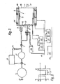
- Figure 1 shows a schematic diagram of a known electric thruster according to the above description.
- propellant gas for example xenon
- a propellant tank 1 through a fill and drain valve 2.
- the tank 1 feeds a plenum tank 3 with propellant gas at reduced pressure through a solenoid operated valve 4.
- the plenum tank 3 is monitored with a pressure sensor 5 and feedback control electronics 6 used to operate the valve 4.
- a solenoid operated thruster inlet valve 7 is opened. Approximately 90% of the propellant gas flowing from the valve 7 is supplied into an ionisation chamber 8 through a main flow assembly inlet 9 connected to a back plate 10 of the chamber 8.
- Approximately 5% of the propellant gas flowing from the valve 7 is supplied via a first tee junction through a hollow cathode 11 into the chamber 8 and picks up electrons which are emitted by the hollow cathode 11. These electrons are accelerated from the region of a keeper 12 towards an anode 13 by an electrostatic field provided between the keeper and the anode and they ionise the propellant gas supplied from the inlet 9 by a collision process.
- a series of solenoids 14 (or possibly permanent magnets) provide a magnetic field which causes the electrons to spiral between the keeper 12 and anode 13 so increasing their path length and hence the number of collisions and the ionisation efficiency.
- a high negative voltage applied to the accelerator grid 16 provides an electrostatic field which accelerates positive propellant ions out of the chamber 8 through the two grids 15 and 16 as an exhaust beam 17 which gives the required thrust.
- the positive xenon ions have an exhaust velocity of approximately 30Km/s and the thrust produced is approximately lOmN. Accelerator grid and beam supply d.c.
- power supplies 20, 21 have terminals connected to the spacecraft potential VO provided by the connection SVO to the spacecraft, to the accelerator grid l6.and to the thruster potential VI as shown.
- Anode and discharge chamber keeper d.c. power supplies 22, 23 have terminals connected to the anode 13, to the keeper 12, and to the thruster potential V1 as shown.
- a heater 24 for the hollow cathode 11 is also connected to the potential V1.
- the supplies 20,21,22,23 and the heater 24 are controlled together with the thruster inlet valve 7 from a central processor (not shown) and switched on simultaneously when thrust is required
- a separate electron emitter known as a neutraliser
- the neutraliser includes a second tee junction which supplies approximately 5% of the propellant gas flowing from the thruster inlet valve 7 through a second hollow cathode 30 which emits electrons to a second keeper 31.
- a neutraliser bias d.c.,power supply 32 has one terminal connected to the spacecraft potential V0 and the other terminal provides a neutraliser potential V2.
- the hollow cathode 30 and keeper 31 are connected to the terminals of a neutraliser keeper d.c. power supply 33 connected to the neutraliser potential V2 and a heater 34- for the hollow cathode 30 is also connected to the neutraliser potential V2.
- the neutraliser power supplies are also switched on under control of the central processor when thrust is required.
- One disadvantage of the separate neutraliser just described is the extra cost in providing the second tee junction propellant supply, the second hollow cathode device, and its associated heater and power supplies. Another disadvantage is that hollow cathode electron emitters presently available are inherently rather unreliable devices due to, for example, the use of a heater which could fail and contamination problems.
- the use of the first hollow cathode device 11, 12 is at present required as part of the preferred means for producing ionisation in the chamber 8,but tne increased risk in using the second hollow cathode device is undesirable for spacecraft where reliability is a prime factor.
- An object of the invention is substantially to overcome the disadvantages just described.
- an electric thruster for spacecraft propulsion including an ionisation chamber, means for providing propellant in the chamber when thrust is required, means for ionising the propellant in the chamber, a grid at one end of the chamber and means for providing an electrostatic field to accelerate positive propellant ions out of the chamber through the grid as an exhaust beam which gives the required thrust, characterised in that said means for providing an electrostatic field comprises an alternating voltage supply connected to the grid such that positive propellant ions and negatively charged particles are alternately accelerated out of the chamber through the grid to provide an exhaust beam having a predetermined net electrical charge.
- the amount of charge contained in the alternating negative and positive sections of the exhaust beam must be equal. Because the electrons are much lighter and more abundant in the ionisation chamber 8 than the positive propellant ions, much shorter electron accelerating periods and much smaller electron accelerating voltages are required than the equivalent positive propellant ion accelerating parameters. As a result a waveform of the type shown in Figure 3 is required to be supplied to the accelerating grid 16 by the alternating voltage power supply 201.
- V3 and V4 are dependent on the type of propellant, and thruster design, and are therefore well defined for any particular thruster.
- the periods tl and t2 for which positive propellant ions and electrons respectively are accelerated are less well defined but again depend upon the thruster design.
- V3 and V4 are -1000V and +5V respectively, and tl is equal to 98% of the waveform period T.
- Spacecraft tend to become electrically charged for a variety of environmental reasons other than that related to the thruster as described above and this is undesirable. Since a system is normally fitted for measuring spacecraft potential it is envisaged that this system can be linked with means for varying the ratio of tl to t2 so that the exhaust beam of the thruster may have a net positive or negative electrical charge which balances these other spacecraft charging effects and maintains a spacecraft zero potential.
- molecular compounds may be used as the propellant in the type of electric thruster to which this invention relates, that is to say as described in the first paragraph of this specification.
- negatively charged particles will be produced in the form of negative ions in the ionisation chamber.
- this invention is applicable to such use of molecular compound propellants so that positive propellant ions and negatively charged particles are alternately accelerated out of the ionisation chamber to provide an exhaust beam having a predetermined net electrical charge.
Landscapes
- Engineering & Computer Science (AREA)
- Chemical & Material Sciences (AREA)
- Combustion & Propulsion (AREA)
- Physics & Mathematics (AREA)
- Plasma & Fusion (AREA)
- Mechanical Engineering (AREA)
- General Engineering & Computer Science (AREA)
- Optics & Photonics (AREA)
- Plasma Technology (AREA)
- Particle Accelerators (AREA)
- Vehicle Cleaning, Maintenance, Repair, Refitting, And Outriggers (AREA)
- Forklifts And Lifting Vehicles (AREA)
Applications Claiming Priority (2)
| Application Number | Priority Date | Filing Date | Title |
|---|---|---|---|
| GB8318919 | 1983-07-13 | ||
| GB8318919 | 1983-07-13 |
Publications (2)
| Publication Number | Publication Date |
|---|---|
| EP0132065A2 true EP0132065A2 (de) | 1985-01-23 |
| EP0132065A3 EP0132065A3 (de) | 1986-05-28 |
Family
ID=10545646
Family Applications (1)
| Application Number | Title | Priority Date | Filing Date |
|---|---|---|---|
| EP84304344A Withdrawn EP0132065A3 (de) | 1983-07-13 | 1984-06-27 | Elektrisches Triebwerk für den Raumantrieb |
Country Status (3)
| Country | Link |
|---|---|
| EP (1) | EP0132065A3 (de) |
| JP (1) | JPS6036787A (de) |
| GB (1) | GB2143281B (de) |
Cited By (10)
| Publication number | Priority date | Publication date | Assignee | Title |
|---|---|---|---|---|
| WO1988008488A1 (en) * | 1987-04-23 | 1988-11-03 | Hughes Aircraft Company | Spacecraft with modulated thrust electrostatic ion thruster and associated method |
| WO1989005404A1 (en) * | 1987-12-11 | 1989-06-15 | Hughes Aircraft Company | Electrostatic ion thruster with improved thrust modulation |
| FR2643421A1 (fr) * | 1987-04-27 | 1990-08-24 | Olin Corp | Procede et ensemble de commande d'amorcage d'un arc dans un reacteur a arc de propulsion |
| EP0560742A1 (de) * | 1992-03-11 | 1993-09-15 | PROEL TECNOLOGIE S.p.A. | Plasmagenerator und dazugehörige Ionisationsvorrichtung |
| RU2166666C2 (ru) * | 1996-02-23 | 2001-05-10 | ТРВ Инк. | Система подачи ракетного топлива к маломощному электродуговому реактивному двигателю и способ подачи топлива |
| EP1621753A1 (de) * | 2004-07-21 | 2006-02-01 | United Technologies Corporation | Antrieb durch energetische Detonation |
| WO2007093699A3 (fr) * | 2006-02-14 | 2007-11-15 | Claude Poher | Dispositif propulseur par acceleration de particules et applications dudit dispositif |
| CN111878336A (zh) * | 2020-07-06 | 2020-11-03 | 安徽华东光电技术研究所有限公司 | 离子推进器 |
| CN111878337A (zh) * | 2020-07-06 | 2020-11-03 | 安徽华东光电技术研究所有限公司 | 离子推进器 |
| CN116971947A (zh) * | 2022-04-29 | 2023-10-31 | 瓦斯里奥斯·霍罗佐格鲁 | 用于航天器的推进的同步多相交变电流静电离子推力器 |
Families Citing this family (4)
| Publication number | Priority date | Publication date | Assignee | Title |
|---|---|---|---|---|
| GB9016567D0 (en) * | 1990-07-27 | 1990-09-12 | Marconi Space Systems Limited | Ion thruster vector control |
| FR2997462B1 (fr) * | 2012-10-30 | 2018-09-14 | Safran Aircraft Engines | Alimentation d'un propulseur ionique en gaz propulsif |
| JP6214874B2 (ja) * | 2013-01-22 | 2017-10-18 | 国立大学法人 東京大学 | イオンエンジンのプラズマ着火用ガス供給方法及びシステム |
| FR3014503B1 (fr) * | 2013-12-11 | 2016-01-01 | Snecma | Systeme de regulation de debit ameliore pour l'alimentation en fluide propulseur d'un propulseur electrique de vehicule spatial |
Family Cites Families (1)
| Publication number | Priority date | Publication date | Assignee | Title |
|---|---|---|---|---|
| DE2052014A1 (de) * | 1970-10-23 | 1972-04-27 | Messerschmitt Boelkow Blohm | Ionentriebwerk |
-
1984
- 1984-06-27 EP EP84304344A patent/EP0132065A3/de not_active Withdrawn
- 1984-06-27 GB GB08416313A patent/GB2143281B/en not_active Expired
- 1984-07-12 JP JP14520584A patent/JPS6036787A/ja active Pending
Cited By (13)
| Publication number | Priority date | Publication date | Assignee | Title |
|---|---|---|---|---|
| WO1988008488A1 (en) * | 1987-04-23 | 1988-11-03 | Hughes Aircraft Company | Spacecraft with modulated thrust electrostatic ion thruster and associated method |
| US4825646A (en) * | 1987-04-23 | 1989-05-02 | Hughes Aircraft Company | Spacecraft with modulated thrust electrostatic ion thruster and associated method |
| FR2643421A1 (fr) * | 1987-04-27 | 1990-08-24 | Olin Corp | Procede et ensemble de commande d'amorcage d'un arc dans un reacteur a arc de propulsion |
| WO1989005404A1 (en) * | 1987-12-11 | 1989-06-15 | Hughes Aircraft Company | Electrostatic ion thruster with improved thrust modulation |
| EP0560742A1 (de) * | 1992-03-11 | 1993-09-15 | PROEL TECNOLOGIE S.p.A. | Plasmagenerator und dazugehörige Ionisationsvorrichtung |
| US5352954A (en) * | 1992-03-11 | 1994-10-04 | Proel Technologie S.P.A. | Plasma generator and associated ionization method |
| RU2166666C2 (ru) * | 1996-02-23 | 2001-05-10 | ТРВ Инк. | Система подачи ракетного топлива к маломощному электродуговому реактивному двигателю и способ подачи топлива |
| EP1621753A1 (de) * | 2004-07-21 | 2006-02-01 | United Technologies Corporation | Antrieb durch energetische Detonation |
| US7246483B2 (en) | 2004-07-21 | 2007-07-24 | United Technologies Corporation | Energetic detonation propulsion |
| WO2007093699A3 (fr) * | 2006-02-14 | 2007-11-15 | Claude Poher | Dispositif propulseur par acceleration de particules et applications dudit dispositif |
| CN111878336A (zh) * | 2020-07-06 | 2020-11-03 | 安徽华东光电技术研究所有限公司 | 离子推进器 |
| CN111878337A (zh) * | 2020-07-06 | 2020-11-03 | 安徽华东光电技术研究所有限公司 | 离子推进器 |
| CN116971947A (zh) * | 2022-04-29 | 2023-10-31 | 瓦斯里奥斯·霍罗佐格鲁 | 用于航天器的推进的同步多相交变电流静电离子推力器 |
Also Published As
| Publication number | Publication date |
|---|---|
| GB2143281A (en) | 1985-02-06 |
| GB8416313D0 (en) | 1984-08-01 |
| JPS6036787A (ja) | 1985-02-25 |
| GB2143281B (en) | 1987-03-18 |
| EP0132065A3 (de) | 1986-05-28 |
Similar Documents
| Publication | Publication Date | Title |
|---|---|---|
| US5924277A (en) | Ion thruster with long-lifetime ion-optics system | |
| EP0132065A2 (de) | Elektrisches Triebwerk für den Raumantrieb | |
| US4838021A (en) | Electrostatic ion thruster with improved thrust modulation | |
| US10172227B2 (en) | Plasma accelerator with modulated thrust | |
| US10480493B2 (en) | Hall effect thruster electrical configuration | |
| US3374941A (en) | Air blower | |
| US8468794B1 (en) | Electric propulsion apparatus | |
| US4486665A (en) | Negative ion source | |
| US7791260B2 (en) | Gas-fed hollow cathode keeper and method of operating same | |
| Wilbur et al. | Ion thruster development trends and status in the United States | |
| JPH0578133B2 (de) | ||
| JPH08500699A (ja) | 閉鎖電子ドリフトを持つ長さの短いプラズマ加速器 | |
| US6960888B1 (en) | Method of producing and accelerating an ion beam | |
| Kaufman et al. | Experimental performance of ion rockets employing electron-bombardment ion sources | |
| US20050005593A1 (en) | Method and apparatus for balancing the emission current of neutralizers in ion thruster arrays | |
| KR20030051762A (ko) | 이온 주입기 빔라인에서의 중성자 방사 방지 장치 | |
| US3304718A (en) | Double optic system for ion engine | |
| EP0637900A1 (de) | Verfahren und Vorrichtung zur Extraktion von Elektronen auf einem Raumfahrzeug | |
| JPS6347226B2 (de) | ||
| Aitken | The precision implant 9000 beam line | |
| US6326630B1 (en) | Ion implanter | |
| EP1604110B1 (de) | Antriebsvorrichtung eines raumflugkörpers und verfahren zur lagesteuerung eines raumflugkörpers mit einer solchen antriebsvorrichtung | |
| Pigeon et al. | Analysis of a near-vacuum hall thruster | |
| Vizir et al. | Ion beam formation under unusual conditions | |
| McComas et al. | Radially uniform electron source |
Legal Events
| Date | Code | Title | Description |
|---|---|---|---|
| PUAI | Public reference made under article 153(3) epc to a published international application that has entered the european phase |
Free format text: ORIGINAL CODE: 0009012 |
|
| AK | Designated contracting states |
Designated state(s): BE DE FR IT NL SE |
|
| PUAL | Search report despatched |
Free format text: ORIGINAL CODE: 0009013 |
|
| AK | Designated contracting states |
Kind code of ref document: A3 Designated state(s): BE DE FR IT NL SE |
|
| STAA | Information on the status of an ep patent application or granted ep patent |
Free format text: STATUS: THE APPLICATION IS DEEMED TO BE WITHDRAWN |
|
| 18D | Application deemed to be withdrawn |
Effective date: 19870129 |
|
| RIN1 | Information on inventor provided before grant (corrected) |
Inventor name: SMITH, PETER |