EP0131719A2 - Adjustable guiding apparatus - Google Patents
Adjustable guiding apparatus Download PDFInfo
- Publication number
- EP0131719A2 EP0131719A2 EP84106015A EP84106015A EP0131719A2 EP 0131719 A2 EP0131719 A2 EP 0131719A2 EP 84106015 A EP84106015 A EP 84106015A EP 84106015 A EP84106015 A EP 84106015A EP 0131719 A2 EP0131719 A2 EP 0131719A2
- Authority
- EP
- European Patent Office
- Prior art keywords
- guide vanes
- guide
- adjustable
- ring
- adjusting ring
- Prior art date
- Legal status (The legal status is an assumption and is not a legal conclusion. Google has not performed a legal analysis and makes no representation as to the accuracy of the status listed.)
- Granted
Links
Images


Classifications
-
- F—MECHANICAL ENGINEERING; LIGHTING; HEATING; WEAPONS; BLASTING
- F04—POSITIVE - DISPLACEMENT MACHINES FOR LIQUIDS; PUMPS FOR LIQUIDS OR ELASTIC FLUIDS
- F04D—NON-POSITIVE-DISPLACEMENT PUMPS
- F04D29/00—Details, component parts, or accessories
- F04D29/40—Casings; Connections of working fluid
- F04D29/42—Casings; Connections of working fluid for radial or helico-centrifugal pumps
- F04D29/44—Fluid-guiding means, e.g. diffusers
- F04D29/46—Fluid-guiding means, e.g. diffusers adjustable
- F04D29/462—Fluid-guiding means, e.g. diffusers adjustable especially adapted for elastic fluid pumps
-
- F—MECHANICAL ENGINEERING; LIGHTING; HEATING; WEAPONS; BLASTING
- F01—MACHINES OR ENGINES IN GENERAL; ENGINE PLANTS IN GENERAL; STEAM ENGINES
- F01D—NON-POSITIVE DISPLACEMENT MACHINES OR ENGINES, e.g. STEAM TURBINES
- F01D17/00—Regulating or controlling by varying flow
- F01D17/10—Final actuators
- F01D17/12—Final actuators arranged in stator parts
- F01D17/14—Final actuators arranged in stator parts varying effective cross-sectional area of nozzles or guide conduits
- F01D17/16—Final actuators arranged in stator parts varying effective cross-sectional area of nozzles or guide conduits by means of nozzle vanes
Definitions
- the invention relates to an adjustable guide apparatus of a turbomachine, in particular an exhaust gas turbine of a turbocharger, with a ring of guide vanes arranged concentrically around a rotor axis, each of which is arranged between end boundaries around pivot axes, which are arranged in the front area of the guide vanes which is assigned to the AU 3 and is flowing are pivotable, one of the end limits being adjustable by means of an adjusting ring or the like.
- DE-OS 23 29 022 describes an adjustable guide device for the guide vanes of a gas turbine, the guide vanes of which are arranged so as to be pivotable about pivot axes. To pivot the guide vanes, they have lateral pins in the area of their leading edges, which engage in axial guide grooves of an adjusting ring. The guide vanes can be pivoted between end limits by means of the adjusting ring, but the guide vanes cannot be pivoted freely. The guide vanes are positively guided in each operating area of the gas turbine in accordance with the setting of the adjusting ring.
- DE-OS 24 55 361 describes an adjustable diffuser of a turbine or a compressor, in which the blades are articulated on the one hand in a housing and on the other hand on an adjusting ring.
- This adjustment ring is adjustable between two fixed stops.
- the guide vanes are therefore mechanically forcibly guided, a comparatively great mechanical outlay being necessary in order to mount each guide vane about two pivot axes each, an eccentric, elongated hole or the like being provided. Furthermore, external adjustment forces have to be applied in two directions for the adjustment of the guide vanes.
- the invention is therefore based on the object of proposing a guide apparatus of the type mentioned at the outset which has a comparatively simple construction and in which the adjusting forces can also be applied in one direction only.
- gap and / or impact losses are to be reduced with a view to low consumption.
- a compact and weight-saving structure and also a high level of operational reliability are to be achieved.
- a functional adjustment to the operational requirements and the installation conditions should be given with a low weight.
- the guide vanes be arranged in such a way that they can be freely pivoted under flow forces in a setting angle range predetermined by means of the end limits.
- the proposed diffuser has a comparatively simple construction, and adjusting forces can only be applied in one direction.
- the guide vanes are automatically adjusted within the limits specified by the end limits in accordance with the direction of the streamline. This results in a not inconsiderable reduction in gap and impact losses in the partial load range if no or even a low boost pressure is required for the engine.
- the freely pivotable guide vanes are thus set to "minimum loss" without the need for a high level of control and regulation, as would be necessary with positively driven guide vanes.
- the guide device has a high level of operational reliability with a simple construction, the adjusting force being able to be introduced practically at any desired point; an adaptation to the respective installation conditions can be done without difficulty.
- the pivotable guide vanes are not adjusted by an external torque acting on their pivot axes, but that they can be freely pivoted between the variable end limits in the partial load range.
- the guide vanes are further turned up to the greatest possible angle given by the end limitation due to the blade forces resulting from the flow which act between the pivot axis and the adjustable end limitation.
- the end limit can be set, for example, according to the charge pressure characteristic.
- the adjustability can be made according to the appropriate parameters in other turbomachines. It can be seen that due to the Adjustability depending on preselectable parameters an optimal adaptation to the respective requirements and operating conditions can be carried out.
- the guide vanes have a lateral guide pin which slides in an adjustable guide groove. It should be noted that the proposed guide groove is adjustable in the desired manner by means of the above-mentioned adjusting ring. Due to the lateral arrangement of the pin, the passage area between the guide vanes remains free.
- an adjustable guide pin is provided in the wall of the flow channel, which slides in a guide groove provided on the end face of the guide vanes or on the downstream profile side.
- the guide pin which is expediently connected directly to the adjusting ring, forms a reliable support or limitation for the guide vanes, with a comparatively low production outlay also being required here.
- the adjusting ring is provided with sawtooth-shaped contact surfaces for the free ends of the guide vanes for an impeller through which centripetal flows.
- the sawtooth-shaped contact surfaces according to the invention are at a smaller distance from the rotor axis than the pivot axes.
- the curve shape can be specified according to the respective requirements.
- the curves are expediently predefined in such a way that a displacement angle of the displacement ring is also assigned a defined displacement angle of the blades, and above all a linear dependency can be predefined without difficulty.
- the free ends of the guide vanes partially rest on the adjusting ring arranged in the flow channel, which is adjustable in the axial direction.
- the adjusting ring is in flow direction behind the pivot axes, so that the unscrewing caused by the blade forces is limited by the contact of the free ends on the adjusting ring.
- At least two guide vanes are coupled to one another and are freely pivotable together.
- the individual guide vanes can therefore no longer be freely pivoted independently of one another, but rather the guide vanes which are coupled to one another can be freely pivoted together.
- the individual blades are thus combined into groups distributed over the circumference.
- the guide vanes which are coupled to one another consequently have the same angle of attack, which ensures a particularly uniform flow against the turbine wheel.
- disadvantageous oscillation or fluttering which may occur in the case of individual blades, can be prevented.
- two are connected to each other, with more than two blades being connected to one another in accordance with the respective requirements, in particular by means of a lever or the like.
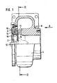
- FIG. 1 shows, purely schematically, an exhaust gas turbine with an impeller 2 through which there is a centripetal flow.
- a spiral inflow channel 4 is provided, through which the exhaust gas flowing radially inward passes in the usual way to the guide vanes 6 distributed over the circumference.
- the guide vanes 6 are arranged in a housing 8 so as to be pivotable about a pivot axis 10, the pivot axis being located in the region of the leading edge 11.
- an adjusting ring 14 which is rotatable in a suitable manner about the rotor axis 12 is also arranged.
- the guide vanes rest with their free, radially inwardly facing ends 16 on a projection 18 of the adjusting ring 14.
- the adjusting ring 14 or the projection 18, corresponding projections also being provided for the other guide vanes distributed over the circumference, has a sawtooth-shaped contour to be explained below.
- These projections 18 create 6 inner end boundaries for the respective guide vanes, against which the guide vanes bear with increasing load; otherwise the guide vanes are freely pivotable about their pivot axis 10.
- the adjusting ring 14 can be adjusted to the desired angular position with respect to the rotor axis 12 by means of suitable adjusting means, which are preferably pneumatic or also mechanical.
- Fig. 2 shows in the left part a view in viewing direction A and also in the right part a section along section line II acc. Fig. 1.
- the adjusting ring 14 has on its radial outer surface the sawtooth-shaped projections 18, with each guide vane 6 being associated with such a projection 18.
- the drawing shows the position in which the flow cross-section between the guide vanes is greatest.
- the flow cross section is reduced by rotating the adjusting ring 14 about the rotor axis 12 in the direction of the arrow 20.
- the free ends 16 of the guide vanes 6 are moved outwards on the sawtooth-shaped contour in the radial direction.
- the adjustment ring 14 designed in this way creates the inner variable end limit for the guide vanes 6.
- the outer end limitation is formed by the next following guide vane in each case in the circumferential direction.
- the guide vanes 6 adjust themselves according to the pressure and flow conditions between these two end limits, as a result of which gap and impact losses are reduced to a minimum and consequently, in this part-load range, compared to fully guided guide vanes, there are not inconsiderably lower losses.
- the sawtooth-shaped curves or surfaces of the projections 18 are designed such that there is a proportional dependence between the change in the angle of rotation of the adjusting ring 14 and the change in the setting angle of the guide vanes 6. It is also essential that there is a narrowing of the flow width in the region of the projections 18 of the adjusting ring 14 and thus in the region of the trailing edges or the free ends of the guide vanes 6.
- Fig. 3 shows purely schematically the diffuser for an exhaust gas turbine with an axially flow through stator, not shown here.
- the adjusting ring 14 Concentric to the rotor axis 12, the adjusting ring 14 can be seen, which is designed here as a hollow ring and which, according to the invention, is arranged radially on the outside in the flow channel.
- the guide vanes 6 can be pivoted about essentially radially oriented pivot axes 10, which are located at the front end or in the region of the leading edges.
- the free end or the trailing edge of the guide vane 6 lies against the end face of the adjusting ring 14 with a small, radially outer part.
- the adjusting ring 14 is guided in a suitable manner in the housing 22, and it can be adjusted parallel to the rotor axis 12, for example via a bolt 24.
- FIG. 4 shows a part of the guide apparatus projected into the drawing plane in the viewing direction B according to FIG. 3.
- the housing 22 has a slanted slot 26 for the bolt 24, so that there is not only an axial adjustability in the direction of the rotor axis but also a rotation about the rotor axis for the adjusting ring 14. According to the invention, this makes it easy to adjust the adjustment ring.
- the guide vanes 6, as can be readily recognized in connection with FIG. 3, rest with the outer part of their trailing edge on the adjusting ring 14, which thus forms the one end limit.
- the end limitation is also changed in this embodiment. It is not necessary to emphasize that the other end limitation is given by the adjacent guide vane.
- FIG. 5 shows a view similar to FIG. 4, but with the three guide vanes 6 shown being coupled to one another by means of a lever 30. Otherwise, the description of FIG. 4 applies accordingly.
- the three guide vanes 6 are coupled to one another by means of the lever 30 in such a way that they can be pivoted together about their pivot axes 10 and thus each assume the same angular position in the partial load range.
- the other guide vanes, not shown here are of course also coupled to one another in groups.
- the guide blades coupled in this way each take the same angular position. The uniformity of the inflow to the turbine wheel is significantly improved and vibrations of individual blades can be prevented.
Abstract
Die Erfindung bezieht sich auf einen verstellbaren Leitapparat einer Strömungsmaschine, insbesondere einer Abgasturbine eines Turboladers, mit einem Kranz von konzentrisch um eine Rotorachse (12) angeordneten Leitschaufeln, die zwischen Endbegrenzungen um Schwenkachsen (10) schwenkbar sind. Die Schwenkachsen (10) sind im vorderen, den Anströmkanten zugeordneten Bereich der Leitschaufeln (6) angeordnet, wobei mittels eines Verstellringes (14) oder dergleichen eine der genannten Endbegrenzungen einstellbar ist. Spalt- und/oder Stoßverluste ergeben sich entsprechend der jeweiligen Einstellung der Leitschaufeln. Es soll die Aufgabe gelöst werden, einen Leitapparat mit geringem konstruktiven Aufwand vorzuschlagen, bei welchem Spalt- und/oder Stoßverluste reduziert werden. Zur Lösung wird vorgeschlagen, daß die Leitschaufeln (6) derart angeordnet sind, daß sie unter den Strömungskräften in einem mittels der Endbegrenzungen vorgegebenen Einstellwinkelbereich frei schwenkbar sind. Die Leitschaufeln (6) sind bei geringer Belastung in dem vorgegebenen Einstellwinkelbereich frei schwenkbar und bei zunehmender Belastung liegen die Leitschaufeln (6) an der einstellbaren Endbegrenzung an.The invention relates to an adjustable diffuser of a turbomachine, in particular an exhaust gas turbine of a turbocharger, with a ring of guide vanes which are arranged concentrically around a rotor axis (12) and can be pivoted between end limits about pivot axes (10). The pivot axes (10) are arranged in the front area of the guide vanes (6) assigned to the leading edges, one of the end limits mentioned being adjustable by means of an adjusting ring (14) or the like. Gap and / or impact losses result in accordance with the respective setting of the guide vanes. The object of the invention is to propose a guide apparatus with little design effort, in which gap and / or impact losses are reduced. As a solution, it is proposed that the guide vanes (6) be arranged in such a way that they can be freely pivoted under the flow forces in a setting angle range predetermined by means of the end limits. The guide vanes (6) can be freely pivoted in the specified setting angle range when the load is low, and the guide vanes (6) rest against the adjustable end limit with increasing load.
Description
Die Erfindung bezieht sich auf einen verstellbaren Leitapparat einer Strömungsmaschine, insbesondere einer Abgasturbine eines Turboladers, mit einem Kranz von konzentrisch um eine Rotorachse angeordneten Leitschaufeln, welche jeweils zwischen Endbegrenzungen um Schwenkachsen, die im vorderen, den AU3ström- kanten zugeordneten Bereich der Leitschaufeln angeordnet sind, schwenkbar sind, wobei mittels eines Verstellringes oder dergleichen eine der Endbegrenzungen einstellbar ist.The invention relates to an adjustable guide apparatus of a turbomachine, in particular an exhaust gas turbine of a turbocharger, with a ring of guide vanes arranged concentrically around a rotor axis, each of which is arranged between end boundaries around pivot axes, which are arranged in the front area of the guide vanes which is assigned to the AU 3 and is flowing are pivotable, one of the end limits being adjustable by means of an adjusting ring or the like.
In der DE-OS 23 29 022 ist ein verstellbarer Leitapparat für die Leitschaufeln einer Gasturbine beschrieben, deren Leitschaufeln um Schwenkachsen schwenkbar angeordnet sind. Zur Verschwenkung der Leitschaufeln weisen diese im Bereich ihrer Anströmkanten seitliche Stifte auf, die in axiale Führungsnuten eines Verstellringes eingreifen. Die Leitschaufeln können zwar zwischen Endbegrenzungen mittels des Verstellringes geschwenkt werden, doch ist eine freie Schwenkbarkeit der Leitschaufeln nicht gegeben. Die Leitschaufeln sind in jedem Betriebsbereich der Gasturbine entsprechend der Einstellung des Verstellringes zwangsgeführt.DE-OS 23 29 022 describes an adjustable guide device for the guide vanes of a gas turbine, the guide vanes of which are arranged so as to be pivotable about pivot axes. To pivot the guide vanes, they have lateral pins in the area of their leading edges, which engage in axial guide grooves of an adjusting ring. The guide vanes can be pivoted between end limits by means of the adjusting ring, but the guide vanes cannot be pivoted freely. The guide vanes are positively guided in each operating area of the gas turbine in accordance with the setting of the adjusting ring.
In der DE-OS 24 55 361 ist ein verstellbarer Leitapparat einer Turbine bzw. eines Kompressors beschrieben, bei welchem die Schaufeln einerseits in einem Gehäuse und andererseits an einem Verstellring angelenkt sind. Dieser Verstellring ist zwischen zwei festen Anschlägen einstellbar. Die Leitschaufeln sind also mechanisch zwangsweise geführt, wobei ein vergleichsweise großer mechanischer Aufwand erforderlich ist, um jede Leitschaufel um jeweils zwei Schwenkachsen, wobei ein Exzenter, Langloch oder dergleichen vorgesehen sind, zu lagern. Ferner müssen für die Verstellung der Leitschaufeln äußere Verstellkräfte in zwei Richtungen aufgebracht werden.DE-OS 24 55 361 describes an adjustable diffuser of a turbine or a compressor, in which the blades are articulated on the one hand in a housing and on the other hand on an adjusting ring. This adjustment ring is adjustable between two fixed stops. The guide vanes are therefore mechanically forcibly guided, a comparatively great mechanical outlay being necessary in order to mount each guide vane about two pivot axes each, an eccentric, elongated hole or the like being provided. Furthermore, external adjustment forces have to be applied in two directions for the adjustment of the guide vanes.
Ferner ist in der US-PS 4 179 247 ein Turbolader mit einem verstellbaren Leitapparat beschrieben, bei welchem die Schwenkachsen jeder Leitschaufel mit einem Hebel drehfest verbunden sind. Diese Hebel stehen mit einem Verstellring, welcher ein Langloch oder dergleichen aufweist, in Wirkverbindung, so daß bei einer Drehung des Verstellringes der Hebel und somit auch die zugeordnete Leitschaufel entsprechend gedreht wird.'Auch hier ist also eine Zwangsführung vorgesehen, wobei die Stellkräfte in beiden Richtungen aufgebracht werden müssen. Aufgrund der Zwangsführung wird dem strömenden Medium die Strömungsrichtung im Leitapparat vorgegeben. Es hat sich gezeigt, daß insbesondere im Teillastbereich des von dem Turbolader aufgeladenen Motors, aufgrund von Spalt- und Stoßverlusten hierdurch der Verbrauch nachteilig beeinflußt wird.Furthermore, a turbocharger with an adjustable guide device is described in US Pat. No. 4,179,247, in which the pivot axes of each guide vane are connected in a rotationally fixed manner with a lever. These levers are operatively connected to an adjusting ring, which has an elongated hole or the like, so that when the adjusting ring rotates, the lever and thus also the associated guide vane is rotated accordingly. Here, too, a positive guidance is provided, the actuating forces in both Directions must be applied. Due to the forced guidance, the direction of flow in the diffuser is specified for the flowing medium. It has been shown that the consumption is adversely affected, in particular in the part-load range of the engine charged by the turbocharger, due to gap and shock losses.
Der Erfindung liegt daher die Aufgabe zugrunde, einen Leitapparat der eingangs genannten Art vorzuschlagen, welcher einen vergleichsweise einfachen konstruktiven Aufbau aufweist und bei welchem die Verstellkräfte auch nur in einer Richtung aufzubringen sind. Darüberhinaus sollen Spalt- und/oder Stoßverluste im Hinblick auf einen niedrigen Verbrauch reduziert werden. Schließlich soll auch die Einleitung der Verstellkraft zu dem Verstellring in einfacher Weise und darüberhinaus auch an der jeweils gewünschten Stelle erfolgen können. Ein kompakter und gewichtsparender Aufbau und ferner eine hohe Betriebssicherheit soll erreicht werden. Ferner soll bei geringem Gewicht eine funktionsgerechte Anpassung an die betrieblichen Anforderungen sowie die Einbaubedingungen gegeben sein.The invention is therefore based on the object of proposing a guide apparatus of the type mentioned at the outset which has a comparatively simple construction and in which the adjusting forces can also be applied in one direction only. In addition, gap and / or impact losses are to be reduced with a view to low consumption. Finally, it should also be possible to introduce the adjusting force to the adjusting ring in a simple manner and, moreover, also at the desired location. A compact and weight-saving structure and also a high level of operational reliability are to be achieved. Furthermore, a functional adjustment to the operational requirements and the installation conditions should be given with a low weight.
Zur Lösung dieser Aufgabe wird vorgeschlagen, daß die Leitschaufeln derart angeordnet sind, daß sie unter Strömungskräften in einem mittels der Endbegrenzungen vorgegebenen Einstellwinkelbereich frei schwenkbar sind.To achieve this object, it is proposed that the guide vanes be arranged in such a way that they can be freely pivoted under flow forces in a setting angle range predetermined by means of the end limits.
Der vorgeschlagene Leitapparat weist einen vergleichsweise einfachen konstruktiven Aufbau auf, und Verstellkräfte sind nur in einer Richtung aufzubringen. Innerhalb der durch die Endbegrenzungen vorgegebenen Grenzen erfolgt bei Normalbetrieb bzw. im Teillastbereich eine automatische Einstellung der Leitschaufeln entsprechend der Stromlinienrichtung. Somit wird eine nicht unerhebliche Reduzierung von Spalt- und Stoßverlusten im Teillastbereich erreicht, wenn kein oder auch nur ein geringer Ladedruck für den Motor erforderlich ist. In diesem Betriebsbereich stellen sich somit die frei schwenkbaren Leitschaufeln auf "Minimalverlust" ein, ohne daß hierfür ein hoher Kontroll- und Regelaufwand, wie es bei zwangsgeführten Leitschaufeln erforderlich wäre, vorzunehmen ist. Darüberhinaus muß festgehalten werden, daß bei erhöhtem Ladedruck im Vergleich mit voll geführten Leitschaufeln übereinstimmende Ergebnisse erzielt werden. Der Leitapparat weist eine hohe Betriebssicherheit bei einer einfachen Bauweise auf, wobei die Verstellkraft praktisch an jedem gewünschten Punkt eingeleitet werden kann; eine Anpassung an die jeweiligen Einbauverhältnisse kann ohne Schwierigkeiten erfolgen. Wesentlich ist hierbei, daß die schwenkbaren Leitschaufeln nicht durch ein äußeres, an ihren Schwenkachsen angreifendes Drehmoment verstellt werden, sondern daß sie im Teillastbereich frei schwenkbar zwischen den variablen Endbegrenzungen sind. Andererseits werden die Leitschaufeln bei weiterer Belastung aufgrund den aus der Strömung resultierenden Schaufelkräften, die zwischen der Schwenkachse und der einstellbaren Endbegrenzung angreifen, auf den jeweils durch die Endbegrenzung vorgegebenen größtmöglichen Winkel aufgedreht. Die Einstellung der Endbegrenzung kann bei einem Turbolader beispielsweise nach der Ladedruckcharakteristik erfolgen. Es bedarf keiner besonderen Hervorhebung, daß bei anderen Strömungsmaschinen die Einstellbarkeit entsprechend den jeweils zweckmäßigen Parametern vorgenommen werden kann. Es ist ersichtlich, daß aufgrund der Einstellbarkeit in Abhängigkeit von vorwählbaren Parametern eine optimale Anpassung an die jeweiligen Anforderungen und Einsatzbedingungen durchführbar ist.The proposed diffuser has a comparatively simple construction, and adjusting forces can only be applied in one direction. During normal operation or in the partial load range, the guide vanes are automatically adjusted within the limits specified by the end limits in accordance with the direction of the streamline. This results in a not inconsiderable reduction in gap and impact losses in the partial load range if no or even a low boost pressure is required for the engine. In this operating range, the freely pivotable guide vanes are thus set to "minimum loss" without the need for a high level of control and regulation, as would be necessary with positively driven guide vanes. In addition, it must be noted that consistent results are achieved with increased boost pressure in comparison with fully guided guide vanes. The guide device has a high level of operational reliability with a simple construction, the adjusting force being able to be introduced practically at any desired point; an adaptation to the respective installation conditions can be done without difficulty. It is essential here that the pivotable guide vanes are not adjusted by an external torque acting on their pivot axes, but that they can be freely pivoted between the variable end limits in the partial load range. On the other hand, the guide vanes are further turned up to the greatest possible angle given by the end limitation due to the blade forces resulting from the flow which act between the pivot axis and the adjustable end limitation. In the case of a turbocharger, the end limit can be set, for example, according to the charge pressure characteristic. There is no special emphasis that the adjustability can be made according to the appropriate parameters in other turbomachines. It can be seen that due to the Adjustability depending on preselectable parameters an optimal adaptation to the respective requirements and operating conditions can be carried out.
In einer besonderen Ausführungsform weisen die Leitschaufeln einen seitlichen Führungsstift auf, der in einer verstellbaren Führungsnut gleitet. Es sei festgehalten, daß mittels des oben genannten Verstellringes die vorgeschlagene Führungsnut in der gewünschten Weise einstellbar ist. Aufgrund der seitlichen Anordnung des Stiftes bleibt der Durchtrittsbereich zwischen den Leitschaufeln frei.In a special embodiment, the guide vanes have a lateral guide pin which slides in an adjustable guide groove. It should be noted that the proposed guide groove is adjustable in the desired manner by means of the above-mentioned adjusting ring. Due to the lateral arrangement of the pin, the passage area between the guide vanes remains free.
In einer alternativen Ausführungsform ist in der Wand des Strömungskanals jeweils ein verstellbarer Führungsstift vorgesehen, welcher in einer an der Stirnseite der Leitschaufeln vorgesehenen Führungsnut oder an der stromabwärts gelegenen Profilseite gleitet. Bei dieser Ausführungsform bildet der zweckmäßig mit dem Verstellring direkt verbundene Führungsstift eine zuverlässige Auflagerung bzw. Begrenzung für die Leitschaufeln, wobei auch hier ein vergleichsweise geringer Fertigungsaufwand erforderlich ist.In an alternative embodiment, an adjustable guide pin is provided in the wall of the flow channel, which slides in a guide groove provided on the end face of the guide vanes or on the downstream profile side. In this embodiment, the guide pin, which is expediently connected directly to the adjusting ring, forms a reliable support or limitation for the guide vanes, with a comparatively low production outlay also being required here.
In einer besonders wesentlichen Ausgestaltung ist für ein zentripetal durchströmtes Laufrad der Verstellring mit sägezahnförmigen Auflageflächen für die freien Enden der Leitschaufeln versehen. Die erfindungsgemäßen sägezahnförmigen Auflageflächen weisen zur Rotorachse einen geringeren Abstand auf als die Schwenkachsen. Die Kurvenform kann den jeweiligen Anforderungen entsprechend vorgegeben werden. Zweckmäßig sind die Kurven derart vorgegeben, daß einem Verstellwinkel des Verstellringes auch ein definierter Verstellwinkel der Schaufeln zugeordnet ist, wobei vor allem auch eine lineare Abhängigkeit ohne Schwierigkeiten vorgegeben werden kann.In a particularly important embodiment, the adjusting ring is provided with sawtooth-shaped contact surfaces for the free ends of the guide vanes for an impeller through which centripetal flows. The sawtooth-shaped contact surfaces according to the invention are at a smaller distance from the rotor axis than the pivot axes. The curve shape can be specified according to the respective requirements. The curves are expediently predefined in such a way that a displacement angle of the displacement ring is also assigned a defined displacement angle of the blades, and above all a linear dependency can be predefined without difficulty.
Bei einer weiteren Ausführungsform für ein axial durchströmtes Laufrad liegen die freien Enden der Leitschaufeln teilweise auf dem im Strömungskanal angeordneten Verstellring auf, welcher in axialer Richtung verstellbar ist. Auch bei dieser Ausführungsform befindet sich der Verstellring in Strömungsrichtung hinter den Schwenkachsen, so daß das durch die Schaufelkräfte bewirkte Aufdrehen durch das Anlagen der freien Enden an den Verstellring begrenzt wird.In a further embodiment for an impeller with axial flow, the free ends of the guide vanes partially rest on the adjusting ring arranged in the flow channel, which is adjustable in the axial direction. In this embodiment too, the adjusting ring is in flow direction behind the pivot axes, so that the unscrewing caused by the blade forces is limited by the contact of the free ends on the adjusting ring.
In einer alternativen Ausführungsform sind wenigstens zwei Leitschaufeln miteinander gekoppelt und gemeinsam frei schwenkbar angeordnet. Die einzelnen Leitschaufeln sind also nicht mehr unabhängig voneinander frei schwenkbar, sondern es sind die jeweils miteinander gekoppelten Leitschaufeln gemeinsam frei schwenkbar. Im Rahmen dieser Erfindung sind über den Umfang verteilt somit die einzelnen Schaufeln zu Gruppen zusammengefaßt. Die miteinander gekoppelten Leitschaufeln weisen folglich untereinander gleiche Anstellwinkel auf, wodurch eine besonders gleichförmige Anströmung des Turbinenrades gewährleistet wird. Darüberhinaus kann aufgrund der erfindungsgemäßen Kopplung verschiedener Leitschaufeln ein nachteiliges Schwingen bzw. Flattern, wie es bei einzelnen Schaufeln unter Umständen eintreten kann, unterbunden werden. Von der gesamten Anzahl der Leitschaufeln sind jeweils zwei miteinander verbunden, wobei den jeweiligen Anforderungen entsprechend auch mehr als zwei Schaufeln, insbesondere mittels eines Hebels oder dergleichen, miteinander verbunden sind.In an alternative embodiment, at least two guide vanes are coupled to one another and are freely pivotable together. The individual guide vanes can therefore no longer be freely pivoted independently of one another, but rather the guide vanes which are coupled to one another can be freely pivoted together. Within the scope of this invention, the individual blades are thus combined into groups distributed over the circumference. The guide vanes which are coupled to one another consequently have the same angle of attack, which ensures a particularly uniform flow against the turbine wheel. In addition, due to the coupling of different guide vanes according to the invention, disadvantageous oscillation or fluttering, which may occur in the case of individual blades, can be prevented. Of the total number of guide vanes, two are connected to each other, with more than two blades being connected to one another in accordance with the respective requirements, in particular by means of a lever or the like.
Ausführungsformen der Erfindung werden nachfolgend anhand der Zeichnung näher erläutert. Es zeigen:
- Fig.l schematisch einen Längsschnitt durch eine Abgasturbine,
- Fig.2 teilweise eine Ansicht in Blickrichtung A) bzw. einen Schnitt entlang Schnittlinie II gem. Fig.1,
- Fig.3 eine prinzipielle Darstellung eines Axialschnittes durch den Strömungskanal von Axial-Leitschaufeln,
- Fig.4 teilweise eine in die Zeichenebene projezierte Ansicht in Blickrichtung B) gem. Fig.3,
- Fig.5 eine Ansicht ähnlich Fig. 4, wobei jedoch drei Leitschaufeln mittels eines Hebels aneinander gekoppelt sind.
- Fig.l schematically shows a longitudinal section through an exhaust gas turbine,
- 2 partially a view in viewing direction A) or a section along section line II acc. Fig.1,
- 3 shows a basic illustration of an axial section through the flow channel of axial guide vanes,
- 4 partially a view projected into the drawing plane in the direction of view B) acc. Fig. 3,
- 5 shows a view similar to FIG. 4, but with three guide vanes coupled to one another by means of a lever.
Fig. 1 zeigt rein schematisch eine Abgasturbine mit einem zentripetal durchströmten Laufrad 2. Es ist ein spiralförmiger Einströmkanal 4 vorhanden, durch welchen in gewohnter Weise das radial nach innen strömende Abgas zu den über den Umfang verteilt angeordneten Leitschaufeln 6 gelangt. Die Leitschaufeln 6 sind in einem Gehäuse 8 um eine Schwenkachse 10 schwenkbar angeordnet, wobei die Schwenkachse sich im Bereich der Anströmkante 11 befindet. Im Gehäuse 8 ist ferner ein in geeigneter Weise um die Rotorachse 12 drehbarer Verstellring 14 angeordnet. Die Leitschaufeln liegen mit ihren freien, radial nach innen weisenden Enden 16 auf einem Vorsprung 18 des Verstellringes 14 auf. Der Verstellring 14 bzw. der Vorsprung 18, wobei entsprechende Vorsprünge auch für die übrigen über den Umfang verteilten Leitschaufeln vorhanden sind, weist eine nachfolgend noch zu erläuternde sägezahnförmige Kontur auf. Durch diese Vorsprünge 18 sind für die jeweiligen Leitschaufeln 6 innere Endbegrenzungen geschaffen, an welchen sich die Leitschaufeln bei zunehmender Belastung anlegen; im übrigen sind die Leitschaufeln um ihre Schwenkachse 10 frei schwenkbar. Mittels geeigneter Verstellmittel, welche bevorzugt pneumatisch oder auch mechanisch ausgebildet sind, ist der Verstellring 14 in die gewünschte Winkelstellung bezüglich der Rotorachse 12 einstellbar.1 shows, purely schematically, an exhaust gas turbine with an
Fig. 2 zeigt im linken Teil eine Ansicht in Blickrichtung A und ferner im rechten Teil einen Schnitt entlang Schnittlinie II gem. Fig. 1. Der Verstellring 14 weist an seiner radialen Außenfläche die sägezahnförmig ausgebildeten Vorsprünge 18 auf, wobei jede Leitschaufel 6 ein derartiger Vorsprung 18 zugeordnet ist. In der Zeichnung ist die Stellung gezeigt, in welcher der Strömungsquerschnitt zwischen den Leitschaufeln am größten ist. Durch Drehen des Verstellringes 14 um die Rotorachse 12 in Richtung des Pfeiles 20 wird der Strömungsquerschnitt verringert. Die freien Enden 16 der Leitschaufeln 6 werden auf der sägezahnförmigen Kontur in radialer Richtung nach außen bewegt. Durch den derart ausgebildeten Verstellring 14 ist die innere variable Endbegrenzung für die Leitschaufeln 6 geschaffen. Die äußere Endbegrenzung wird bei dieser erfindungsgemäßen Ausführungsform durch die Umfangsrichtung jeweils nächst folgende Leitschaufel gebildet. Bei geringer Belastung stellen sich die Leitschaufeln 6 entsprechend der Druck- und Strömungsverhältnisse zwischen diesen beiden Endbegrenzungen ein, wodurch Spalt- und Stoßverluste auf ein Minimum reduziert werden und folglich in diesem Teillastbereich, im Vergleich zu voll geführten Leitschaufeln, sich nicht unerheblich geringere Verluste ergeben. Erfindungsgemäß sind die sägezahnförmigen Kurven bzw. Oberflächen der Vor-sprünge 18 derart ausgebildet, daß eine proportinale Abhängigkeit zwischen der Änderung des Drehwinkels des Verstellringes 14 und der Änderung des Einstellwinkels der Leitschaufeln 6 gegeben ist. Ferner ist von wesentlicher Bedeutung, daß im Bereich der Vorsprünge 18 des Verstellringes 14 und somit im Bereich der Abströmkanten bzw. der freien Enden der Leitschaufeln 6 eine Verengung der Strömungsbreite gegeben ist.Fig. 2 shows in the left part a view in viewing direction A and also in the right part a section along section line II acc. Fig. 1. The adjusting
Fig. 3 zeigt rein schematisch den Leitapparat für eine Abgasturbine mit einem hier nicht weiter dargestellten axial durchströmten Leitrad. Konzentrisch zur Rotorachse 12 ist der Verstellring 14 zu sehen, welcher hier als ein Hohlring ausgebildet ist und welcher erfindungsgemäß im Strömungskanal radial außen angeordnet ist. Die Leitschaufeln 6 sind um im wesentlichen radial ausgerichtete Schwenkachsen 10 schwenkbar, welche sich am vordern Ende bzw. im Bereich der Anströmkanten befinden. Das freie Ende bzw. die Abströmkante der Leitschaufel 6 liegt mit einem kleinen, radial außen liegenden Teil an der Stirnfläche des Verstellringes 14 an. Der Verstellring 14 ist in geeigneter Weise im Gehäuse 22 geführt, und er ist parallel zur Rotorachse 12 beispielsweise über einen Bolzen 24 verstellbar.Fig. 3 shows purely schematically the diffuser for an exhaust gas turbine with an axially flow through stator, not shown here. Concentric to the
Fig. 4 zeigt in die Zeichenebene projeziert einen Teil des Leitapparates in Blickrichtung B gem. Fig. 3. Das Gehäuse 22 weist für den Bolzen 24 einen schräg liegenden Schlitz 26 auf, so daß nicht nur eine axiale Verstellbarkeit in Richtung der Rotorachse sondern gleichzeitig auch eine Drehung um die Rotorachse für den Verstellring 14 gegeben ist. Erfindungsgemäß ist dadurch eine leichte Einstellbarkeit des Verstellringes gewährleistet. Die Leitschaufeln 6 liegen, wie in Verbindung mit Fig. 3 ohne weiteres erkennbar, mit dem äußeren Teil ihrer Abströmkante an dem Verstellring 14 an, der somit die eine Endbegrenzung bildet. Durch Bewegung des Verstellringes 14 in Richtung des Pfeiles 20 wird auch bei dieser Ausführungsform die Endbegrenzung verändert. Es bedarf keiner besonderen Hervorhebung, daß die andere Endbegrenzung durch die benachbarte Leitschaufel jeweils gegeben ist. Mit zunehmendem Ladedruck wird die durch den Pfeil 28 angedeutete Kraftkomponente des einströmenden Mediums größer, wodurch die Leitschaufeln 6 fest an die mittels des Verstellringes 14 vorgegebene Endbegrenzung gedrückt werden. Bei geringerem Ladedruck, also im Teillastbereich, geht die genannte Komponente gegen Null, und die erfindungsgemäß zwischen den Endbegrenzungen frei schwenkbaren Leitschaufeln stellen sich in die jeweils günstigste Winkelstellung automatisch ein. Eine nicht unwesentliche Reduzierung von Spalt- und Stoßverlusten ist gegeben.FIG. 4 shows a part of the guide apparatus projected into the drawing plane in the viewing direction B according to FIG. 3. The
In Fig. 5 ist eine Ansicht ähnlich wie Fig. 4 gezeigt, wobei jedoch die drei dargestellten Leitschaufeln 6 mittels eines Hebels 30 aneinander gekoppelt sind. Im übrigen gilt hierzu die Beschreibung von Fig. 4 entsprechend. Mittels des Hebels 30 sind die drei Leitschaufeln 6 derart miteinander gekoppelt, daß sie gemeinsam um ihre Schwenkachsen 10 schwenkbar sind und somit im Teillastbereich jeweils die gleiche Winkelstellung einnehmen. Über den Umfang verteilt sind selbstverständlich auch die übrigen hier nicht dargestellten Leitschaufeln jeweils in Gruppen aneinander gekoppelt. Im Gegensatz zu Ausführungsformen mit einzeln schwenkbaren Schaufeln, welche aufgrund der Spiralenströmung leicht voneinander abweichende Stellwinkel einnehmen, nehmen die derart miteinander gekoppelten Leitschaufeln jeweils die gleiche Winkelstellung ein. Die Gleichförmigkeit der Anströmung des Turbinenrades wird nicht unwesentlich verbessert und Schwingungen einzelner Schaufeln können unterbunden werden.5 shows a view similar to FIG. 4, but with the three
- 2 Laufrad2 impeller
- 4 Einströmkanal4 inflow channel
- 6 Leitschaufel6 guide vane
- 8 Gehäuse8 housing
- 10 Schwenkachse10 swivel axis
- 11 Anströmkante11 leading edge
- 12 Rotorachse12 rotor axis
- 14 Verstellring14 adjusting ring
- 16 freies Ende16 free end
- 18 Vorsprung18 head start
- 20 Pfeil20 arrow
- 22 Gehäuse22 housing
- 24 Bolzen24 bolts
- 26 Schlitz26 slot
- 28 Pfeil28 arrow
- 30 Hebel30 levers
Claims (6)
Priority Applications (1)
| Application Number | Priority Date | Filing Date | Title |
|---|---|---|---|
| AT84106015T ATE27335T1 (en) | 1983-07-16 | 1984-05-26 | ADJUSTABLE CONTROL UNIT. |
Applications Claiming Priority (2)
| Application Number | Priority Date | Filing Date | Title |
|---|---|---|---|
| DE3325756 | 1983-07-16 | ||
| DE3325756A DE3325756C1 (en) | 1983-07-16 | 1983-07-16 | Adjustable nozzle |
Publications (3)
| Publication Number | Publication Date |
|---|---|
| EP0131719A2 true EP0131719A2 (en) | 1985-01-23 |
| EP0131719A3 EP0131719A3 (en) | 1985-03-13 |
| EP0131719B1 EP0131719B1 (en) | 1987-05-20 |
Family
ID=6204187
Family Applications (1)
| Application Number | Title | Priority Date | Filing Date |
|---|---|---|---|
| EP84106015A Expired EP0131719B1 (en) | 1983-07-16 | 1984-05-26 | Adjustable guiding apparatus |
Country Status (5)
| Country | Link |
|---|---|
| US (1) | US4657480A (en) |
| EP (1) | EP0131719B1 (en) |
| JP (1) | JPS6053602A (en) |
| AT (1) | ATE27335T1 (en) |
| DE (2) | DE3325756C1 (en) |
Cited By (1)
| Publication number | Priority date | Publication date | Assignee | Title |
|---|---|---|---|---|
| US6824355B2 (en) | 2000-03-17 | 2004-11-30 | Abb Turbo Systems Ag | Distributor for an exhaust gas turbine with an axial flow |
Families Citing this family (15)
| Publication number | Priority date | Publication date | Assignee | Title |
|---|---|---|---|---|
| US4629396A (en) * | 1984-10-17 | 1986-12-16 | Borg-Warner Corporation | Adjustable stator mechanism for high pressure radial turbines and the like |
| DE3516738A1 (en) * | 1985-05-09 | 1986-11-13 | Mtu Motoren- Und Turbinen-Union Friedrichshafen Gmbh, 7990 Friedrichshafen | FLOWING MACHINE |
| DE3541508C1 (en) * | 1985-11-23 | 1987-02-05 | Kuehnle Kopp Kausch Ag | Exhaust gas turbocharger |
| US4741666A (en) * | 1985-12-23 | 1988-05-03 | Ishikawajima-Harima Jukogyo Kabushiki Kaisha | Variable displacement turbocharger |
| JPS63183207A (en) * | 1987-01-23 | 1988-07-28 | Honda Motor Co Ltd | Variable displacement type turbine |
| US5266003A (en) * | 1992-05-20 | 1993-11-30 | Praxair Technology, Inc. | Compressor collector with nonuniform cross section |
| US5437539A (en) * | 1992-07-22 | 1995-08-01 | Massachusetts Institute Of Technology | Apparatus for the dynamic control of rotating stall and surge in turbo machines and the like |
| US5730580A (en) * | 1995-03-24 | 1998-03-24 | Concepts Eti, Inc. | Turbomachines having rogue vanes |
| DE19644892A1 (en) * | 1996-10-29 | 1998-04-30 | Johannes Werner | Intake control for turbo machines and IC engines |
| US6174129B1 (en) | 1999-01-07 | 2001-01-16 | Siemens Westinghouse Power Corporation | Turbine vane clocking mechanism and method of assembling a turbine having such a mechanism |
| DE50205152D1 (en) | 2001-03-30 | 2006-01-12 | Abb Turbo Systems Ag Baden | turbocharger |
| DE102004040536A1 (en) * | 2004-08-20 | 2006-02-23 | Volkswagen Ag | Exhaust gas turbocharger for motor vehicle, has adjusting ring connected with guide vane along direction of flow of exhaust gas flow, where angle position of vane relative to direction of flow is adjusted by flexible deformation of vane |
| US20060177305A1 (en) * | 2005-02-07 | 2006-08-10 | Hoang Khanh C | Centrifugal volute pump with discontinuous vane-island diffuser |
| US10240480B2 (en) * | 2014-11-21 | 2019-03-26 | Borgwarner Inc. | Variable turbine geometry vane with single-axle, self-centering pivot feature |
| US10883379B2 (en) * | 2018-05-11 | 2021-01-05 | Rolls-Royce Corporation | Variable diffuser having a respective penny for each vane |
Citations (5)
| Publication number | Priority date | Publication date | Assignee | Title |
|---|---|---|---|---|
| GB304638A (en) * | 1927-09-21 | 1929-01-21 | Neil Shaw Muir | Improvements in or relating to centrifugal blowers, compressors and the like |
| GB731822A (en) * | 1952-03-14 | 1955-06-15 | Power Jets Res & Dev Ltd | Improvements relating to turbines or compressors for operation with gaseous fluids |
| US3957392A (en) * | 1974-11-01 | 1976-05-18 | Caterpillar Tractor Co. | Self-aligning vanes for a turbomachine |
| US4029433A (en) * | 1974-12-17 | 1977-06-14 | Caterpillar Tractor Co. | Stator vane assembly |
| DE3030079A1 (en) * | 1980-08-08 | 1982-03-11 | Kraftwerk Union AG, 4330 Mülheim | Non-return valve for blower intake esp. of high temp. reactor - has series of small pivoted blades in annular intake duct |
Family Cites Families (10)
| Publication number | Priority date | Publication date | Assignee | Title |
|---|---|---|---|---|
| US1136877A (en) * | 1914-06-01 | 1915-04-20 | Thomas Henry Collett Homersham | Centrifugal blower and other centrifugal machine of a similar nature. |
| DE518787C (en) * | 1926-11-02 | 1931-02-19 | Georges Claude | Turbine for operation with water vapor or other propellants at low pressure |
| DE889091C (en) * | 1940-03-08 | 1953-09-07 | Versuchsanstalt Fuer Luftfahrt | Continuously adjustable guide vane system |
| FR1041161A (en) * | 1951-08-14 | 1953-10-21 | Napier & Son Ltd | Improvements to axial fluid flow reaction apparatus comprising at least one row of radial vanes |
| DE2262031A1 (en) * | 1972-12-19 | 1974-06-20 | Klein Schanzlin & Becker Ag | ENTRY CONTROL UNIT FOR FLOW MACHINERY |
| DE2329022A1 (en) * | 1973-06-07 | 1975-02-20 | Volkswagenwerk Ag | Adjustable gas turbine stator blade assembly - pivoted blade has radial pin engaging axial slot in external rotary ring |
| DE2455361A1 (en) * | 1973-12-11 | 1975-06-12 | Plessey Handel Investment Ag | TURBINE OR COMPRESSOR IN PARTICULAR FOR TURBOCHARGERS |
| US4179247A (en) * | 1977-01-14 | 1979-12-18 | Wrr Industries, Inc. | Turbocharger having variable area turbine nozzles |
| JPS5724500A (en) * | 1980-07-22 | 1982-02-09 | Mitsubishi Heavy Ind Ltd | Variable stator blade mechanism for turbomachine |
| US4484857A (en) * | 1982-09-21 | 1984-11-27 | Pierre Patin | Bladed turbine pump with adjustable guide vanes |
-
1983
- 1983-07-16 DE DE3325756A patent/DE3325756C1/en not_active Expired
-
1984
- 1984-05-26 AT AT84106015T patent/ATE27335T1/en not_active IP Right Cessation
- 1984-05-26 DE DE8484106015T patent/DE3463812D1/en not_active Expired
- 1984-05-26 EP EP84106015A patent/EP0131719B1/en not_active Expired
- 1984-07-11 US US06/629,601 patent/US4657480A/en not_active Expired - Fee Related
- 1984-07-13 JP JP59145877A patent/JPS6053602A/en active Granted
Patent Citations (5)
| Publication number | Priority date | Publication date | Assignee | Title |
|---|---|---|---|---|
| GB304638A (en) * | 1927-09-21 | 1929-01-21 | Neil Shaw Muir | Improvements in or relating to centrifugal blowers, compressors and the like |
| GB731822A (en) * | 1952-03-14 | 1955-06-15 | Power Jets Res & Dev Ltd | Improvements relating to turbines or compressors for operation with gaseous fluids |
| US3957392A (en) * | 1974-11-01 | 1976-05-18 | Caterpillar Tractor Co. | Self-aligning vanes for a turbomachine |
| US4029433A (en) * | 1974-12-17 | 1977-06-14 | Caterpillar Tractor Co. | Stator vane assembly |
| DE3030079A1 (en) * | 1980-08-08 | 1982-03-11 | Kraftwerk Union AG, 4330 Mülheim | Non-return valve for blower intake esp. of high temp. reactor - has series of small pivoted blades in annular intake duct |
Cited By (1)
| Publication number | Priority date | Publication date | Assignee | Title |
|---|---|---|---|---|
| US6824355B2 (en) | 2000-03-17 | 2004-11-30 | Abb Turbo Systems Ag | Distributor for an exhaust gas turbine with an axial flow |
Also Published As
| Publication number | Publication date |
|---|---|
| EP0131719B1 (en) | 1987-05-20 |
| ATE27335T1 (en) | 1987-06-15 |
| DE3463812D1 (en) | 1987-06-25 |
| DE3325756C1 (en) | 1984-09-13 |
| JPH0347401B2 (en) | 1991-07-19 |
| JPS6053602A (en) | 1985-03-27 |
| US4657480A (en) | 1987-04-14 |
| EP0131719A3 (en) | 1985-03-13 |
Similar Documents
| Publication | Publication Date | Title |
|---|---|---|
| EP0598174B1 (en) | Turbo charger for a combustion engine | |
| EP2025945B1 (en) | Flow working machine with ring canal wall fitting | |
| DE3412916C2 (en) | Fan blades | |
| DE4009223C2 (en) | ||
| EP0131719B1 (en) | Adjustable guiding apparatus | |
| EP1774179B1 (en) | Compressor blade | |
| DE4232400C1 (en) | ||
| EP1609999A2 (en) | Turbo machine | |
| DE102008032661A1 (en) | flow machine | |
| DE102008011644A1 (en) | Housing structuring for axial compressor in the hub area | |
| EP1788255A1 (en) | Impeller of radial compressor | |
| DE2262883A1 (en) | CENTRIFUGAL PUMP WITH VARIABLE DIFFUSER | |
| CH647042A5 (en) | EVAPORATION PIPE OF A TURBINE. | |
| DE2744366A1 (en) | IMPELLER FOR A RADIAL TURBO COMPRESSOR | |
| DE102007056953B4 (en) | Turbomachine with Ringkanalwandausnehmung | |
| DE2953300C1 (en) | Exhaust pipe of a turbine | |
| DE102005040574A1 (en) | Gap control device for a gas turbine | |
| DE2905738C2 (en) | ||
| DE60128324T2 (en) | Gas turbine blade shape | |
| DE3223164C2 (en) | Turbo machine rotor assembly and blade | |
| DE1476907B2 (en) | Gas turbine engine with two coaxially arranged rotating rotors | |
| DE102009054771A1 (en) | Turbo compressor | |
| EP2617947B1 (en) | Aircraft gas turbine engine with adjustable fan | |
| DE10205363A1 (en) | gas turbine | |
| WO1995025895A1 (en) | Device for reducing noise in centrifugal pumps |
Legal Events
| Date | Code | Title | Description |
|---|---|---|---|
| PUAI | Public reference made under article 153(3) epc to a published international application that has entered the european phase |
Free format text: ORIGINAL CODE: 0009012 |
|
| PUAL | Search report despatched |
Free format text: ORIGINAL CODE: 0009013 |
|
| 17P | Request for examination filed |
Effective date: 19840526 |
|
| AK | Designated contracting states |
Designated state(s): AT DE FR GB IT |
|
| AK | Designated contracting states |
Designated state(s): AT DE FR GB IT |
|
| GRAA | (expected) grant |
Free format text: ORIGINAL CODE: 0009210 |
|
| AK | Designated contracting states |
Kind code of ref document: B1 Designated state(s): AT DE FR GB IT |
|
| ITF | It: translation for a ep patent filed |
Owner name: ING. PIOVESANA PAOLO |
|
| REF | Corresponds to: |
Ref document number: 27335 Country of ref document: AT Date of ref document: 19870615 Kind code of ref document: T |
|
| ET | Fr: translation filed | ||
| REF | Corresponds to: |
Ref document number: 3463812 Country of ref document: DE Date of ref document: 19870625 |
|
| PLBE | No opposition filed within time limit |
Free format text: ORIGINAL CODE: 0009261 |
|
| STAA | Information on the status of an ep patent application or granted ep patent |
Free format text: STATUS: NO OPPOSITION FILED WITHIN TIME LIMIT |
|
| 26N | No opposition filed | ||
| ITTA | It: last paid annual fee | ||
| PGFP | Annual fee paid to national office [announced via postgrant information from national office to epo] |
Ref country code: GB Payment date: 19930422 Year of fee payment: 10 |
|
| PGFP | Annual fee paid to national office [announced via postgrant information from national office to epo] |
Ref country code: AT Payment date: 19930428 Year of fee payment: 10 |
|
| PGFP | Annual fee paid to national office [announced via postgrant information from national office to epo] |
Ref country code: FR Payment date: 19930511 Year of fee payment: 10 |
|
| PGFP | Annual fee paid to national office [announced via postgrant information from national office to epo] |
Ref country code: DE Payment date: 19930618 Year of fee payment: 10 |
|
| PG25 | Lapsed in a contracting state [announced via postgrant information from national office to epo] |
Ref country code: GB Effective date: 19940526 Ref country code: AT Effective date: 19940526 |
|
| GBPC | Gb: european patent ceased through non-payment of renewal fee |
Effective date: 19940526 |
|
| PG25 | Lapsed in a contracting state [announced via postgrant information from national office to epo] |
Ref country code: FR Effective date: 19950131 |
|
| PG25 | Lapsed in a contracting state [announced via postgrant information from national office to epo] |
Ref country code: DE Effective date: 19950201 |
|
| REG | Reference to a national code |
Ref country code: FR Ref legal event code: ST |