EP0131426A2 - Strangpressen von Metall - Google Patents
Strangpressen von Metall Download PDFInfo
- Publication number
- EP0131426A2 EP0131426A2 EP84304558A EP84304558A EP0131426A2 EP 0131426 A2 EP0131426 A2 EP 0131426A2 EP 84304558 A EP84304558 A EP 84304558A EP 84304558 A EP84304558 A EP 84304558A EP 0131426 A2 EP0131426 A2 EP 0131426A2
- Authority
- EP
- European Patent Office
- Prior art keywords
- die
- sleeve
- unit
- metal
- holder
- Prior art date
- Legal status (The legal status is an assumption and is not a legal conclusion. Google has not performed a legal analysis and makes no representation as to the accuracy of the status listed.)
- Withdrawn
Links
Images

Classifications
-
- B—PERFORMING OPERATIONS; TRANSPORTING
- B21—MECHANICAL METAL-WORKING WITHOUT ESSENTIALLY REMOVING MATERIAL; PUNCHING METAL
- B21C—MANUFACTURE OF METAL SHEETS, WIRE, RODS, TUBES OR PROFILES, OTHERWISE THAN BY ROLLING; AUXILIARY OPERATIONS USED IN CONNECTION WITH METAL-WORKING WITHOUT ESSENTIALLY REMOVING MATERIAL
- B21C25/00—Profiling tools for metal extruding
- B21C25/02—Dies
-
- B—PERFORMING OPERATIONS; TRANSPORTING
- B21—MECHANICAL METAL-WORKING WITHOUT ESSENTIALLY REMOVING MATERIAL; PUNCHING METAL
- B21C—MANUFACTURE OF METAL SHEETS, WIRE, RODS, TUBES OR PROFILES, OTHERWISE THAN BY ROLLING; AUXILIARY OPERATIONS USED IN CONNECTION WITH METAL-WORKING WITHOUT ESSENTIALLY REMOVING MATERIAL
- B21C23/00—Extruding metal; Impact extrusion
- B21C23/005—Continuous extrusion starting from solid state material
Definitions
- This invention relates to a die unit and machinery for extrusion of metal. More especially (but not exclusively) it relates to machinery of the kind in which a passageway is formed between an arcuate first member and a second member in the form of a wheel having a circumferential groove formed in its peripheral surface into which groove the first member projects, the wheel being rotatable to urge material in the passageway towards one end (the exit end) thereof, an abutment member extending across the passageway at the exit end thereof and at least one die orifice through the abutment member or through a part of the arcuate first member adjacent the abutment member.
- the abutment member may be large enough to block the end of the passageway completely (as described in the specification of UK Patent 1370894) but especially when the material to be extruded is a relatively hard metal, such as copper, we prefer that the abutment member is of substantially smaller cross-section than the passageway and leaves a substantial gap between the abutment member and the groove surface and that the material being extruded is Allowed to adhere to the groove surface, whereby a substantial proportion of the metal (as distinct from the inevitable leakage of flash through a working clearance) extends through the clearance and remains as a lining in the groove to re-enter the passageway while the remainder of the metal extrudes through the die orifice(s), as described in our UK Patent No. 20693898.
- Conform machinery Such machinery is commonly known as “Conform” machinery, and will be referred to as such hereinafter.
- a die-unit for extrusion apparatus comprises a die and a die holder in which the die is supported but is surrounded over at least a substantial part of its length by a sleeve extending from the working face between the die and the die holder and made of a metal soft compared with the die and the die holder.
- the invention includes also any extrusion machine incorporating the die unit described, an extrusion method in which it is used and products of the method, including round wire made by a Conform machine (as defined).
- the die unit is preferably a separate insert, but if desired the die holder could be directly formed in the shoe, or the abutment of the machine.
- the sleeve extends to the end of the die at its entry end but stops short of the exit end of the die sufficiently to provide positive location and pressure-tight engagement.
- the die is held in the die holder by means of a close fitting ring of hard metal or a machined step in the die holder.
- the sleeve can be formed merely by leaving a clearance which becomes filled with the metal being extruded, or a preformed ring of that metal can be used; but to avoid a risk of damage to the die and/or the die holder when the machine is taken to pieces after use it is preferable to use a sleeve made of another metal (soft compared with the die and the die holder) that will not strongly adhere to the metal to be extruded.
- mild steel is a suitable material; others include titanium, nickel and pure iron.
- a wheel 1 (the curvature of which is too slight to be visible at this scale) is formed with a rectangular groove 2, that forms three walls of the extrusion passageway 3.
- the fourth wall is formed by an assembly comprising a shoe 4 (a small portion of which is shown), and an abutment 5 projects into the passageway.
- a radial extrusion die 6 is formed in a die holder 7 (which is preferably a separate component, though it might be integral with either the abutment or the shoe).
- the shoe, abutment and die area are of high- strength materials and are held in position by heavy-duty support members (not shown), and cooling means is provided.
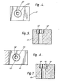
- Figures 2 and 3 show a die 6 mounted conventionally in a die holder 7 and providing a cylindrical orifice 8 relieved by a counterbore 9 to provide a clearance around the extruded product.
- Figures 4 and 5 show a die unit, in accordance with the invention, comprising a die 10, a die holder 11 and a sleeve 12 of mild steel (which is soft compared with the die and die holder and does not strongly adhere to copper) surrounding the die over its whole length.
- a die unit in accordance with the invention, comprising a die 10, a die holder 11 and a sleeve 12 of mild steel (which is soft compared with the die and die holder and does not strongly adhere to copper) surrounding the die over its whole length.
- the alternative die unit of Figures 6 and 7 differs in that the sleeve 12 is replaced by a hard metal ring 13 (which positions the die) and a clearance 14 in which a copper sleeve will be formed as extrusion commences.
- This die unit is effective, but is less satisfactory than the die unit of Figures 4 and 5 as there is a risk of damage when the copper discard is pulled from the die unit when the machine is taken to pieces after use.
- the die holder had overall dimensions 20 x 15 x 15 mm and the dies used had a length of 4 mm (of which the parallel part of the bore was 3 mm) and a diameter of 7 mm.
- the first three dies were conventionally mounted, as Figures 2 and 3.
- the first had a bore whose maximum and minimum diameters were 2.500 and 2.496 mm and produced wire of consistently oval cross-section with maximum and minimum diameters of 2.481 and 2.460 mm respectively (2.47 + 0.6%);
- the second had a bore whose maximum and minimum diameters were 2.502 and 2.497 mm and produced wire of consistently oval cross-section with maximum and minimum diameters of 2.488 and 2.455 mm respectively (2.47 + 0.8%);
- the third had a bore whose maximum and minimum diameters were 2.550 and 2.547 mm and produced wire of consistently oval cross-section with maximum and minimum diameters of 2.517 and 2.482 mm respectively (2.50 + 0.8%).
- the fourth and fifth dies were mounted as shown in Figures 4 and 5 using a mild steel sleeve 0.5 mm thick.
- the fourth had an almost perfectly round bore with a diameter of 2.280 mm and produced wire that was substantially round with a diameter of 2.2245 + 0.0021 mm (better than + 0.1%).
- the fifth had a bore with maximum and minimum diameters of 3.120 and 3.118 mm and produced wire that was substantially round with a diameter of 3.0580 + 0.0028 mm (again better than + 0.1%).
- the sixth.die was mounted as shown in Figures 6 and 7 using a preformed copper sleeve 0.5 mm thick and 2.5 mm long, the hard steel sleeve 13 correspondingly being 1.5 mm long.
- the sixth die had maximum and minimum diameters of 2.500 and 2.496 mm (substantially identical with the first die) and produced copper wire that was substantially round with diameters in the range 2.480 to 2.476 mm (2.478 + 0.1%).
Landscapes
- Engineering & Computer Science (AREA)
- Mechanical Engineering (AREA)
- Extrusion Of Metal (AREA)
- Metal Extraction Processes (AREA)
- Glass Compositions (AREA)
Applications Claiming Priority (4)
| Application Number | Priority Date | Filing Date | Title |
|---|---|---|---|
| GB838318485A GB8318485D0 (en) | 1983-07-08 | 1983-07-08 | Extrusion of metal |
| GB8318485 | 1983-07-08 | ||
| GB8401047 | 1984-01-16 | ||
| GB848401047A GB8401047D0 (en) | 1984-01-16 | 1984-01-16 | Extrusion of metal |
Publications (2)
| Publication Number | Publication Date |
|---|---|
| EP0131426A2 true EP0131426A2 (de) | 1985-01-16 |
| EP0131426A3 EP0131426A3 (de) | 1985-07-31 |
Family
ID=26286567
Family Applications (1)
| Application Number | Title | Priority Date | Filing Date |
|---|---|---|---|
| EP84304558A Withdrawn EP0131426A3 (de) | 1983-07-08 | 1984-07-04 | Strangpressen von Metall |
Country Status (12)
| Country | Link |
|---|---|
| EP (1) | EP0131426A3 (de) |
| AU (1) | AU567949B2 (de) |
| CA (1) | CA1245599A (de) |
| DK (1) | DK334084A (de) |
| FI (1) | FI842730A (de) |
| GB (1) | GB2143455B (de) |
| HK (1) | HK48287A (de) |
| IE (1) | IE55423B1 (de) |
| NO (1) | NO842773L (de) |
| NZ (1) | NZ208808A (de) |
| SG (1) | SG21287G (de) |
| ZW (1) | ZW9284A1 (de) |
Cited By (1)
| Publication number | Priority date | Publication date | Assignee | Title |
|---|---|---|---|---|
| EP0233064A2 (de) * | 1986-02-06 | 1987-08-19 | Alform Alloys Limited | Strangpressvorrichtung |
Citations (5)
| Publication number | Priority date | Publication date | Assignee | Title |
|---|---|---|---|---|
| GB1370894A (en) * | 1971-03-12 | 1974-10-16 | Atomic Energy Authority Uk | Extrusion |
| DE2506701A1 (de) * | 1975-02-18 | 1976-08-19 | Eberhard Dipl Ing Wolff | Umformwerkzeug |
| DE2818171A1 (de) * | 1977-06-20 | 1978-12-21 | Carmet Co | Werkzeug und verfahren zu seiner herstellung |
| EP0032668A1 (de) * | 1980-01-18 | 1981-07-29 | Karl Sieber GmbH & Co. KG Fabrik für Umformwerkzeuge | Matrize für Massivumformung im Kalt- oder Halbwarmverfahren |
| GB2069389A (en) * | 1980-02-19 | 1981-08-26 | Bicc Ltd | Continuous Friction-actuated Extrusion |
Family Cites Families (1)
| Publication number | Priority date | Publication date | Assignee | Title |
|---|---|---|---|---|
| AU452096B2 (en) * | 1971-03-12 | 1974-08-29 | United Kingdom Atomic Energy Authority | Improvements in or relating to extrusion |
-
1984
- 1984-06-20 ZW ZW92/84A patent/ZW9284A1/xx unknown
- 1984-06-21 CA CA000457124A patent/CA1245599A/en not_active Expired
- 1984-06-27 AU AU29947/84A patent/AU567949B2/en not_active Ceased
- 1984-07-04 EP EP84304558A patent/EP0131426A3/de not_active Withdrawn
- 1984-07-04 GB GB08417086A patent/GB2143455B/en not_active Expired
- 1984-07-06 FI FI842730A patent/FI842730A/fi not_active Application Discontinuation
- 1984-07-06 NZ NZ208808A patent/NZ208808A/en unknown
- 1984-07-06 NO NO842773A patent/NO842773L/no unknown
- 1984-07-06 DK DK334084A patent/DK334084A/da unknown
- 1984-07-06 IE IE1722/84A patent/IE55423B1/en unknown
-
1987
- 1987-03-02 SG SG212/87A patent/SG21287G/en unknown
- 1987-06-25 HK HK482/87A patent/HK48287A/xx unknown
Patent Citations (5)
| Publication number | Priority date | Publication date | Assignee | Title |
|---|---|---|---|---|
| GB1370894A (en) * | 1971-03-12 | 1974-10-16 | Atomic Energy Authority Uk | Extrusion |
| DE2506701A1 (de) * | 1975-02-18 | 1976-08-19 | Eberhard Dipl Ing Wolff | Umformwerkzeug |
| DE2818171A1 (de) * | 1977-06-20 | 1978-12-21 | Carmet Co | Werkzeug und verfahren zu seiner herstellung |
| EP0032668A1 (de) * | 1980-01-18 | 1981-07-29 | Karl Sieber GmbH & Co. KG Fabrik für Umformwerkzeuge | Matrize für Massivumformung im Kalt- oder Halbwarmverfahren |
| GB2069389A (en) * | 1980-02-19 | 1981-08-26 | Bicc Ltd | Continuous Friction-actuated Extrusion |
Cited By (2)
| Publication number | Priority date | Publication date | Assignee | Title |
|---|---|---|---|---|
| EP0233064A2 (de) * | 1986-02-06 | 1987-08-19 | Alform Alloys Limited | Strangpressvorrichtung |
| EP0233064A3 (de) * | 1986-02-06 | 1989-07-12 | Alform Alloys Limited | Strangpressvorrichtung |
Also Published As
| Publication number | Publication date |
|---|---|
| DK334084A (da) | 1985-01-09 |
| IE55423B1 (en) | 1990-09-12 |
| NZ208808A (en) | 1987-01-23 |
| ZW9284A1 (en) | 1984-09-05 |
| HK48287A (en) | 1987-07-03 |
| DK334084D0 (da) | 1984-07-06 |
| FI842730A (fi) | 1985-01-09 |
| IE841722L (en) | 1985-01-08 |
| CA1245599A (en) | 1988-11-29 |
| EP0131426A3 (de) | 1985-07-31 |
| FI842730A0 (fi) | 1984-07-06 |
| SG21287G (en) | 1987-07-10 |
| NO842773L (no) | 1985-01-09 |
| GB2143455A (en) | 1985-02-13 |
| GB2143455B (en) | 1986-12-31 |
| AU2994784A (en) | 1985-01-10 |
| GB8417086D0 (en) | 1984-08-08 |
| AU567949B2 (en) | 1987-12-10 |
Similar Documents
| Publication | Publication Date | Title |
|---|---|---|
| CA1182778A (en) | Rapid extrusion of hot-short-sensitive alloys | |
| CA2454392A1 (en) | Improved centrifugally-cast tube and related method and apparatus for making same | |
| CA2401102A1 (en) | Wire electrode for spark erosion cutting | |
| EP0073101B1 (de) | Durch Reibung betätigte Strangpressen | |
| AU583571B2 (en) | Extrusion dies | |
| US4040875A (en) | Ductile cast iron articles | |
| US4270373A (en) | Apparatus and process for the fluid lubrication drawing of composite metal wires | |
| EP0131426A2 (de) | Strangpressen von Metall | |
| US4038858A (en) | Ceramic die and method of using same | |
| KR920703230A (ko) | 금속압출부재 | |
| US20080173063A1 (en) | Torsional wire treatment drawing system | |
| GB2143166A (en) | Extrusion of metal | |
| US3230759A (en) | Extrusion die and the like | |
| US3766768A (en) | Method of and means for commencing a deforming operation, e. g. hydrostatic extrusion of a billet | |
| EP0276958A2 (de) | Verfahren zur Herstellung von Aluminiumzylindern mit sehr glatter Oberfläche | |
| KR940011144B1 (ko) | 분할가능한 다이 | |
| EP0135989A2 (de) | Strangpressen von Metall | |
| GB2102321A (en) | Friction-actuated extrusion | |
| SU596318A1 (ru) | Сборна матрица дл гидроэкструдировани проволоки | |
| EP0198942A1 (de) | Verfahren zur Herstellung einer verbrauchbaren Schweisszwischenlage und nach dem Verfahren hergestelltes Produkt | |
| GB2092930A (en) | Metalworking tool with insert | |
| SU1675010A1 (ru) | Устройство дл волочени в режиме гидродинамического трени | |
| Fuhrman | Internal Ring Gear Cold Extrusion Process | |
| RU2101109C1 (ru) | Волока | |
| SU1752467A2 (ru) | Устройство дл волочени в режиме гидродинамического трени |
Legal Events
| Date | Code | Title | Description |
|---|---|---|---|
| PUAI | Public reference made under article 153(3) epc to a published international application that has entered the european phase |
Free format text: ORIGINAL CODE: 0009012 |
|
| AK | Designated contracting states |
Designated state(s): AT BE CH DE FR IT LI LU NL SE |
|
| PUAL | Search report despatched |
Free format text: ORIGINAL CODE: 0009013 |
|
| AK | Designated contracting states |
Designated state(s): AT BE CH DE FR IT LI LU NL SE |
|
| STAA | Information on the status of an ep patent application or granted ep patent |
Free format text: STATUS: THE APPLICATION IS DEEMED TO BE WITHDRAWN |
|
| 18D | Application deemed to be withdrawn |
Effective date: 19860401 |
|
| RIN1 | Information on inventor provided before grant (corrected) |
Inventor name: FAIREY, NORMAN REGINALD |