EP0131293A1 - Releasable hinge for a bracelet - Google Patents
Releasable hinge for a bracelet Download PDFInfo
- Publication number
- EP0131293A1 EP0131293A1 EP84107954A EP84107954A EP0131293A1 EP 0131293 A1 EP0131293 A1 EP 0131293A1 EP 84107954 A EP84107954 A EP 84107954A EP 84107954 A EP84107954 A EP 84107954A EP 0131293 A1 EP0131293 A1 EP 0131293A1
- Authority
- EP
- European Patent Office
- Prior art keywords
- bracelet
- cradle
- elements
- hinge
- spindle
- Prior art date
- Legal status (The legal status is an assumption and is not a legal conclusion. Google has not performed a legal analysis and makes no representation as to the accuracy of the status listed.)
- Granted
Links
Images


Classifications
-
- A—HUMAN NECESSITIES
- A44—HABERDASHERY; JEWELLERY
- A44C—PERSONAL ADORNMENTS, e.g. JEWELLERY; COINS
- A44C5/00—Bracelets; Wrist-watch straps; Fastenings for bracelets or wrist-watch straps
- A44C5/18—Fasteners for straps, chains or the like
- A44C5/22—Fasteners for straps, chains or the like for closed straps
- A44C5/24—Fasteners for straps, chains or the like for closed straps with folding devices
-
- E—FIXED CONSTRUCTIONS
- E05—LOCKS; KEYS; WINDOW OR DOOR FITTINGS; SAFES
- E05D—HINGES OR SUSPENSION DEVICES FOR DOORS, WINDOWS OR WINGS
- E05D1/00—Pinless hinges; Substitutes for hinges
- E05D1/04—Pinless hinges; Substitutes for hinges with guide members shaped as circular arcs
-
- E—FIXED CONSTRUCTIONS
- E05—LOCKS; KEYS; WINDOW OR DOOR FITTINGS; SAFES
- E05D—HINGES OR SUSPENSION DEVICES FOR DOORS, WINDOWS OR WINGS
- E05D7/00—Hinges or pivots of special construction
- E05D7/10—Hinges or pivots of special construction to allow easy separation or connection of the parts at the hinge axis
- E05D7/1061—Hinges or pivots of special construction to allow easy separation or connection of the parts at the hinge axis in a radial direction
- E05D7/1066—Hinges or pivots of special construction to allow easy separation or connection of the parts at the hinge axis in a radial direction requiring a specific angular position
-
- Y—GENERAL TAGGING OF NEW TECHNOLOGICAL DEVELOPMENTS; GENERAL TAGGING OF CROSS-SECTIONAL TECHNOLOGIES SPANNING OVER SEVERAL SECTIONS OF THE IPC; TECHNICAL SUBJECTS COVERED BY FORMER USPC CROSS-REFERENCE ART COLLECTIONS [XRACs] AND DIGESTS
- Y10—TECHNICAL SUBJECTS COVERED BY FORMER USPC
- Y10T—TECHNICAL SUBJECTS COVERED BY FORMER US CLASSIFICATION
- Y10T24/00—Buckles, buttons, clasps, etc.
- Y10T24/21—Strap tighteners
- Y10T24/2102—Cam lever and loop
- Y10T24/2104—Step adjusted
- Y10T24/2115—Jewelry
-
- Y—GENERAL TAGGING OF NEW TECHNOLOGICAL DEVELOPMENTS; GENERAL TAGGING OF CROSS-SECTIONAL TECHNOLOGIES SPANNING OVER SEVERAL SECTIONS OF THE IPC; TECHNICAL SUBJECTS COVERED BY FORMER USPC CROSS-REFERENCE ART COLLECTIONS [XRACs] AND DIGESTS
- Y10—TECHNICAL SUBJECTS COVERED BY FORMER USPC
- Y10T—TECHNICAL SUBJECTS COVERED BY FORMER US CLASSIFICATION
- Y10T24/00—Buckles, buttons, clasps, etc.
- Y10T24/21—Strap tighteners
- Y10T24/2143—Strap-attached folding lever
- Y10T24/2155—Jewelry-watch straps
-
- Y—GENERAL TAGGING OF NEW TECHNOLOGICAL DEVELOPMENTS; GENERAL TAGGING OF CROSS-SECTIONAL TECHNOLOGIES SPANNING OVER SEVERAL SECTIONS OF THE IPC; TECHNICAL SUBJECTS COVERED BY FORMER USPC CROSS-REFERENCE ART COLLECTIONS [XRACs] AND DIGESTS
- Y10—TECHNICAL SUBJECTS COVERED BY FORMER USPC
- Y10T—TECHNICAL SUBJECTS COVERED BY FORMER US CLASSIFICATION
- Y10T24/00—Buckles, buttons, clasps, etc.
- Y10T24/47—Strap-end-attaching devices
- Y10T24/4782—Watch strap
Definitions
- the invention relates to a hinge serving as a hinge for two elements of a bracelet and arranged to allow the attachment or detachment of the two said elements.
- a bracelet To fit around the wrist, a bracelet must have a reduced opening so as not to slip on the hand. To detach it from the wrist, this bracelet can either be provided with a clasp which separates it into two parts, or equipped with a developable device allowing it to be enlarged so that it can pass freely over the hand.
- German document GM 75 07 948 entitled “Foldable closure for watch strap” describes a device having a first element forming a frame and a second element in the form of a plate, the second sliding in the first, and capable of being separated. '' of one another if an elastic retaining tab is actuated.
- this device has the disadvantage of taking up space in the thickness direction of the bracelet and also of being more complicated to manufacture.
- the present invention proposes a new form of removable hinge for a bracelet executed according to the means which appear in the claims, a hinge which finds its use in particular in a watch bracelet.
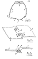
- Figures la, 2a and 3a show a wristwatch with said wallet closure.
- To the watch 1 are attached the two strands of the bracelet 2 composed between themselves of articulated links 3.
- the other ends of the strands 2 are provided with a wallet closure system comprising at least two elements 5 and 6 in the form of plates elongated. At one end of each of the plates is the hinged device 7 which is the subject of the present invention.
- Figure 3a shows the bracelet in the closed position when worn on the wrist.
- the two elements 5 and 6, which have a curved shape to match the contour of the wrist, are then folded over one another and the hinge 7 is hooked.
- Figure 2a shows the bracelet in the open position.
- the two elements 5 and 6 are developed in relation to each other to give a larger extension to the bracelet and thus allow it to be passed over the hand.
- the hinge 7 is hung.
- FIG. 1 shows the bracelet in a position such that the elements 5 and 6 are separated from each other by the hinge being recessed 7. To cause this recess, it is necessary to bring said elements into a predetermined angular position, in this case in a position opposite to that which they occupied in FIG. 3a.
- this device makes it possible to separate the bracelet into two parts for the reasons mentioned above. Despite this, this bracelet nevertheless retains the role of an ordinary wallet bracelet which aims to avoid its complete detachment and its possible fall when it is removed from the wrist because, as we have understood, it is necessary to bring the articulated elements in a very particular position to cause them to drop out and this particular position is not encountered when the bracelet is manipulated simply to put it on or take it off.
- FIGS. 1a, 2a and 3a correspond respectively Figures 1b, 2b and 3b as well as Figures 1c, 2c and 3c, drawn in the same positions and to which we will now refer to describe the hinge object of the present invention.
- the element 6 of the bracelet carries two sets each composed of a pin 10 and a first cradle 11.
- the cradle 11 is coaxial with the pin 10 and a space 12 is provided between the two .
- the cradle 11 has the shape of a hollow half-cylinder.
- Each of the two assemblies thus formed is attached to the element 6 by a single central part 13.
- the other element 5 of the bracelet carries two second cradles 14 which are attached to the element 5 each by a part 15.
- the cradle 14 is shaped to be introduced into the space 12, that is to say that the cross section of the cradle 14 is substantially the same as the cross section of the space 12. In the situation presented in FIG.
- Figure 1c is a schematic section through one of the hinges of Figure 1b and makes it even better understand how we fit the elements 5 and 6 into each other.
- FIG. 2b When the elements 5 and 6 have been hooked to each other and the element 5 has been subjected to a rotation of approximately 180 °, we are in the presence of the situation shown in FIG. 2b. As soon as the element 5 is pivoted, the second cradle 14 slides in the space 12 and is articulated on the spindle 10. The hinge is engaged and FIG. 2b, like FIG. 2c which completes it, illustrates the case where the elongated wallet plates are developed end to end to give the bracelet its maximum extension.
- FIG. 3b and 3c illustrate the case where the bracelet is completely closed when the bracelet is attached to the wrist. It can be seen that the element 5 has been rotated by approximately 360 ° with respect to the situation shown in FIG. 1b and is now placed under the element 6 on which it remains attached. In this case, however, and as shown more particularly in FIG. 3c, the hinge remains attached, not by the cradle 14 which is released from the space 12, but by the element 5 which is retained by the element 6.
- the removable hinge takes up no more space than an ordinary non-removable hinge. Therefore, there is no extra thickness to be expected as is the case in other constructions.
- the proposed hinge is very simple to use and requires no spring-loaded control parts. Finally, it can be implemented in already existing portfolio systems since it will then suffice to modify only the hinge.
- the invention is not limited to an articulation between two elements comprising the first two assemblies each composed of a spindle and a first cradle and the second two second cradles as has been shown in the drawing. It will be understood that a simplified execution could only comprise a single assembly formed by a pin 10 and a first cradle 11 attached to the element 6 and only one second cradle 14 attached to the element 5.
- the invention can be applied to simple jewelry bracelets or even to a leather bracelet. It finds a particularly welcome application when a watch is attached to this bracelet.
Abstract
Charnière (7) servant d'articulation à deux éléments (5, 6) d'un bracelet et permettant l'accrochage ou le décrochage desdits éléments quand ils occupent l'un par rapport à l'autre une position angulaire prédéterminée. Le premier élément (6) porte un ensemble composé d'une broche (10) et d'un premier berceau (11) entourant partiellement la broche avec laquelle il est coaxial, un espace (12) étant ménagé entre la broche et le premier berceau. Le second élément porte un second berceau (14) susceptible de glisser dans l'espace (12) pour être articulé sur la broche et maintenir les deux éléments accrochés l'un à l'autre dans une plage angulaire donnée. L'invention peut être utilisée sur un fermoir à portefeuille d'un bracelet-montre.Hinge (7) serving as a hinge for two elements (5, 6) of a bracelet and allowing the attachment or detachment of said elements when they occupy one with respect to the other a predetermined angular position. The first element (6) carries an assembly composed of a spindle (10) and a first cradle (11) partially surrounding the spindle with which it is coaxial, a space (12) being provided between the spindle and the first cradle . The second element carries a second cradle (14) capable of sliding in the space (12) to be articulated on the spindle and to keep the two elements hooked to one another within a given angular range. The invention can be used on a wallet clasp of a watch strap.
Description
L'invention est relative à une charnière servant d'articulation à deux éléments d'un bracelet et arrangée pour permettre l'accrochage ou le décrochage des deux dits éléments.The invention relates to a hinge serving as a hinge for two elements of a bracelet and arranged to allow the attachment or detachment of the two said elements.
Pour tenir autour du poignet, un bracelet doit avoir une ouverture réduite pour ne pas glisser sur la main. Pour le détacher du poignet, ce bracelet peut être, soit muni d'un fermoir qui le sépare en deux parties, soit équipé d'un dispositif développable permettant de l'agrandir pour le faire passer librement par dessus la main.To fit around the wrist, a bracelet must have a reduced opening so as not to slip on the hand. To detach it from the wrist, this bracelet can either be provided with a clasp which separates it into two parts, or equipped with a developable device allowing it to be enlarged so that it can pass freely over the hand.
Dans le dernier cas cité, on a trouvé souhaitable de pouvoir séparer le bracelet en deux parties pour rendre plus aisé son transport ou son exposition dans une vitrine par exemple. Ainsi, le document allemand GM 75 07 948 intitulé "Fermeture pliable pour bracelet de montre" décrit un dispositif présentant un premier élément formant cadre et un second élément en forme de plaque, le second glissant dans le premier, et susceptibles d'être séparés l'un de l'autre si l'on actionne une languette élastique de retenue. Ce dispositif présente cependant l'inconvénient de prendre de la place dans le sens de l'épaisseur du bracelet et aussi d'être plus compliqué à fabriquer.In the latter case, it was found desirable to be able to separate the bracelet into two parts to make it easier to transport or display in a display case, for example. Thus, the German document GM 75 07 948 entitled "Foldable closure for watch strap" describes a device having a first element forming a frame and a second element in the form of a plate, the second sliding in the first, and capable of being separated. '' of one another if an elastic retaining tab is actuated. However, this device has the disadvantage of taking up space in the thickness direction of the bracelet and also of being more complicated to manufacture.
Pour remédier à ces inconvénients, la présente invention propose une nouvelle forme de charnière démontable pour bracelet exécutée selon les moyens qui apparaissent dans les revendications, charnière qui trouve son utilisation notamment dans un bracelet-montre.To remedy these drawbacks, the present invention proposes a new form of removable hinge for a bracelet executed according to the means which appear in the claims, a hinge which finds its use in particular in a watch bracelet.
L'invention sera comprise maintenant à l'aide de la description qui suit et des dessins qui l'illustrent à titre d'exemple dans lesquels :
- la figure la présente le bracelet de montre à portefeuille en position décrochée.
- la figure lb montre en perspective la charnière servant d'articulation à deux éléments du bracelet, quand ledit bracelet est en position décrochée.
- la figure lc montre en coupe la charnière en position décrochée.
- les figures 2a, 2b et 2c présentent les mêmes vues que celles ci-dessus, les éléments composant la charnière étant en position accrochée et le bracelet ouvert.
- les figures 3a, 3b et 3c présentent les mêmes vues que celles ci-dessus, les éléments composant la charnière étant en position accrochée et le bracelet fermé.
- the figure shows the wallet watch strap in the off-hook position.
- FIG. 1B shows in perspective the hinge serving as an articulation for two elements of the bracelet, when said bracelet is in the off-hook position.
- Figure lc shows in section the hinge in the off-hook position.
- Figures 2a, 2b and 2c show the same views as those above, the components of the hinge being in the hooked position and the bracelet open.
- Figures 3a, 3b and 3c show the same views as those above, the components of the hinge being in the hooked position and the bracelet closed.
Les figures la, 2a et 3a représentent une montre-bracelet à fermeture dite portefeuille. A la montre 1 sont attachés les deux brins du bracelet 2 composés entre eux-mêmes de maillons articulés 3. Les autres extrémités des brins 2 sont munis d'un système de fermeture à portefeuille comportant au moins deux éléments 5 et 6 en forme de plaques allongées. A une extrémité de chacune des plaques se trouve le dispositif à charnière 7 objet de la présente invention.Figures la, 2a and 3a show a wristwatch with said wallet closure. To the watch 1 are attached the two strands of the
La figure 3a montre le bracelet en position fermée quand il est porté au poignet. Les deux éléments 5 et 6, qui présentent une forme incurvée pour épouser le contour du poignet, sont alors rabattus l'un sur l'autre et la charnière 7 est accrochée. La figure 2a montre le bracelet en position ouverte. Les deux éléments 5 et 6 sont développés l'un par rapport a l'autre pour donner une plus grande extension au bracelet et lui permettre ainsi d'être passé par dessus la main. La également, la charnière 7 est accrochée. Enfin, la figure la présente le bracelet dans une position telle que les éléments 5 et 6 sont séparés l'un de l'autre par décrochement de la charnière 7. Pour provoquer ce décrochement, 11 faut amener lesdits éléments dans une position angulaire prédéterminée, en l'occurrence dans une position opposée à celle qu'ils occupaient en figure 3a. On comprendra que ce dispositif permet de séparer le bracelet en deux parties pour les raisons invoquées plus haut. Malgré cela, ce bracelet conserve cependant le rôle d'un bracelet portefeuille ordinaire qui a pour but d'éviter son détachement complet et sa chute éventuelle quand on l'enlève du poignet car, on l'a compris, il faut amener les éléments articulés dans une position bien particulière pour les conduire à se décrocher et cette position particulière ne se rencontre pas quand on manipule le bracelet simplement pour le mettre ou l'enlever.Figure 3a shows the bracelet in the closed position when worn on the wrist. The two
A chacune des figures la, 2a et 3a correspondent respectivement les figures lb, 2b et 3b ainsi que les figures 1c, 2c et 3c, dessinées dans les mêmes positions et auxquelles on se référera maintenant pour décrire la charnière objet de la présente invention.To each of FIGS. 1a, 2a and 3a correspond respectively Figures 1b, 2b and 3b as well as Figures 1c, 2c and 3c, drawn in the same positions and to which we will now refer to describe the hinge object of the present invention.
Sur la figure lb, on voit que l'élément 6 du bracelet porte deux ensembles composés chacun d'une broche 10 et d'un premier berceau 11. Le berceau 11 est coaxial à la broche 10 et un espace 12 est ménagé entre les deux. Dans l'exemple, le berceau 11 présente la forme d'un demi-cylindre creux. Chacun des deux ensembles ainsi constitués est attaché à l'élément 6 par une pièce centrale unique 13. L'autre élément 5 du bracelet porte deux seconds berceaux 14 qui sont attachés à l'élément 5 chacun par une pièce 15. Le berceau 14 est conformé pour être introduit dans 1' espace 12, c'est-à-dire que la section droite du berceau 14 est sensiblement la même que la section droite de l'espace 12. Dans la situation présentée à la figure lb, les éléments 5 et 6 occupent une position angulaire prédéterminée leur permettant d'être introduits l'un dans l'autre. C'est la position d'accrochage ou de décrochage. La figure 1c est une coupe schématique pratiquée à travers une des charnières de la figure lb et fait encore mieux comprendre comment on emboîte les éléments 5 et 6 l'un dans l'autre.In FIG. 1b, it can be seen that the
Lorsque les éléments 5 et 6 ont été accrochés l'un à l'autre et qu'on a fait subir à l'élément 5 une rotation d'environ 180°, on est en présence de la situation montrée en figure 2b. Dès qu'on fait pivoter l'élément 5, le second berceau 14 glisse dans l'espace 12 et s'articule sur la broche 10. La charnière est en prise et la figure 2b, comme la figure 2c qui la complète, illustre le cas où les plaques allongées du portefeuille sont développées bout à bout pour donner au bracelet son extension maximum.When the
Enfin, les figures 3b et 3c illustrent le cas où le bracelet est complètement fermé quand le bracelet est attaché au poignet. On voit que l'élément 5 a été tourné d'environ 360° par rapport à la situation montrée en figure lb et se trouve maintenant disposé sous l'élément 6 sur lequel il reste accroché. Dans ce cas cependant et comme le montre plus particulièrement la figure 3c, la charnière reste accrochée, non par le berceau 14 qui est libéré de l'espace 12, mais par l'élément 5 qui est retenu par l'élément 6.Finally, Figures 3b and 3c illustrate the case where the bracelet is completely closed when the bracelet is attached to the wrist. It can be seen that the
On voit d'emblée les avantages procurés par l'invention qui vient d'être décrite. La charnière démontable ne prend pas plus de place qu'une charnière ordinaire non démontable. De ce fait, il n'y a pas de sur-épaisseur à prévoir comme c'est le cas dans d'autres constructions. La charnière proposée est d'une utilisation très simple et ne nécessite aucune pièce de commande à ressort. Enfin, elle peut être mise en oeuvre dans des systèmes à portefeuille déjà existants puisqu'il suffira alors de ne modifier que la charnière.We immediately see the advantages of the invention which has just been described. The removable hinge takes up no more space than an ordinary non-removable hinge. Therefore, there is no extra thickness to be expected as is the case in other constructions. The proposed hinge is very simple to use and requires no spring-loaded control parts. Finally, it can be implemented in already existing portfolio systems since it will then suffice to modify only the hinge.
L'invention n'est pas limitée à une articulation entre deux éléments comprenant le premier deux ensembles composés chacun d'une broche et d'un premier berceau et le second deux seconds berceaux comme cela a été montré au dessin. On comprendra qu'une exécution simplifiée ne pourrait comporter qu'un seul ensemble formé d'une broche 10 et d'un premier berceau 11 attaché à l'élément 6 et qu'un seul second berceau 14 attaché à l'élément 5.The invention is not limited to an articulation between two elements comprising the first two assemblies each composed of a spindle and a first cradle and the second two second cradles as has been shown in the drawing. It will be understood that a simplified execution could only comprise a single assembly formed by a
L'invention peut être appliquée à de simples bracelets de joaillerie ou même à un bracelet cuir. Elle trouve une application particulièrement bienvenue quand une montre est attachée à ce bracelet.The invention can be applied to simple jewelry bracelets or even to a leather bracelet. It finds a particularly welcome application when a watch is attached to this bracelet.
Claims (4)
Applications Claiming Priority (2)
| Application Number | Priority Date | Filing Date | Title |
|---|---|---|---|
| FR8311918A FR2548879B1 (en) | 1983-07-11 | 1983-07-11 | REMOVABLE HINGE FOR BRACELET |
| FR8311918 | 1983-07-11 |
Publications (2)
| Publication Number | Publication Date |
|---|---|
| EP0131293A1 true EP0131293A1 (en) | 1985-01-16 |
| EP0131293B1 EP0131293B1 (en) | 1986-10-29 |
Family
ID=9290928
Family Applications (1)
| Application Number | Title | Priority Date | Filing Date |
|---|---|---|---|
| EP84107954A Expired EP0131293B1 (en) | 1983-07-11 | 1984-07-06 | Releasable hinge for a bracelet |
Country Status (6)
| Country | Link |
|---|---|
| US (1) | US4546522A (en) |
| EP (1) | EP0131293B1 (en) |
| JP (1) | JPS60215303A (en) |
| DE (1) | DE3461051D1 (en) |
| FR (1) | FR2548879B1 (en) |
| HK (1) | HK34792A (en) |
Cited By (3)
| Publication number | Priority date | Publication date | Assignee | Title |
|---|---|---|---|---|
| WO2008043998A2 (en) * | 2006-10-12 | 2008-04-17 | Cedardell Limited | A security band and lock assembly for the security band |
| CN107620534A (en) * | 2017-08-25 | 2018-01-23 | 中山立方体智能家居有限公司 | Whirlpool turns attachment structure and turns the door of attachment structure, window using the whirlpool |
| IT202000021895A1 (en) * | 2020-09-17 | 2022-03-17 | Promotion Spa | IMPROVED BUCKLE WITH ASSEMBLED AND DISASSEMBLE ELEMENTS |
Families Citing this family (18)
| Publication number | Priority date | Publication date | Assignee | Title |
|---|---|---|---|---|
| JPS6424280U (en) * | 1987-07-29 | 1989-02-09 | ||
| US5259540A (en) * | 1989-04-25 | 1993-11-09 | Skidata Computer Gesellschaft M.B.H. | Data carrier |
| ITMI910764U1 (en) * | 1991-09-06 | 1993-03-08 | Gtf Srl | CLOSING DEVICE FOR WATCH BRACELETS IN METAL OF FABRIC OR SPILED TYPE, BRACELETS, JEWELRY AND SIMILAR |
| CH690894A5 (en) * | 1996-07-01 | 2001-02-28 | Vacheron & Constantin S A | Folding clasp, in particular with button. |
| JPH10271196A (en) * | 1997-03-25 | 1998-10-09 | Seiko Epson Corp | Wrist mount type communication equipment |
| GB2469406B (en) * | 2005-11-10 | 2011-01-19 | Wing Hon Metal Manufactory Ltd | Elongate band,wristwatch comprising same and watchcase |
| AU2008322428B2 (en) * | 2007-11-16 | 2012-09-13 | Belkin International, Inc. | Clamp braces and methods for manufacturing, selling, and using the same |
| US20110085297A1 (en) * | 2009-10-14 | 2011-04-14 | General Dynamics C4 Systems, Inc. | Self Releasing Hinge |
| JP4986271B2 (en) * | 2010-06-18 | 2012-07-25 | カシオ計算機株式会社 | Watch bands and watches |
| TWI548820B (en) * | 2015-01-08 | 2016-09-11 | 宏碁股份有限公司 | Hinge device |
| US9498029B2 (en) * | 2015-03-13 | 2016-11-22 | Google Inc. | Clasp mechanisms for wristwatch bands |
| US11054035B2 (en) | 2015-03-24 | 2021-07-06 | Quickhub, Llc | Pipe connector systems, devices and methods |
| US10557578B2 (en) | 2015-03-24 | 2020-02-11 | Quickhub, Llc | Pipe connector systems, devices and methods |
| US11073233B2 (en) | 2015-03-24 | 2021-07-27 | Quickhub, Llc | Pipe connector systems, devices and methods |
| US10100956B2 (en) | 2015-03-24 | 2018-10-16 | Quickhub, Llc | Pipe connector systems, devices and methods |
| US10253885B2 (en) | 2015-03-24 | 2019-04-09 | Quickhub, Llc | Pipe connector systems, devices and methods |
| PL413125A1 (en) * | 2015-07-14 | 2017-01-16 | Vts Spółka Z Ograniczoną Odpowiedzialnością | Hinge |
| EP4159080B1 (en) * | 2021-10-01 | 2024-03-27 | Omega SA | Adjustable bracelet clasp |
Citations (5)
| Publication number | Priority date | Publication date | Assignee | Title |
|---|---|---|---|---|
| CH344583A (en) * | 1958-07-11 | 1960-02-15 | Gay Freres Sa | Clasp for bracelet |
| US3233277A (en) * | 1963-05-29 | 1966-02-08 | Jaylis Ind Inc | Hinge |
| GB1080331A (en) * | 1963-10-11 | 1967-08-23 | Ingenior Et Fernholt & Giertse | Flexible sectional structure |
| FR2091611A5 (en) * | 1970-05-15 | 1972-01-14 | Leroy Victor | |
| DE2748185A1 (en) * | 1977-10-27 | 1979-05-03 | Hesterberg & Soehne F | Hinge for goods vehicle side boards - ensures detaching of boards but holds reliably in position |
Family Cites Families (7)
| Publication number | Priority date | Publication date | Assignee | Title |
|---|---|---|---|---|
| US1970041A (en) * | 1934-01-16 | 1934-08-14 | Sammartino & Sanchirico Compan | Bracelet |
| US2455302A (en) * | 1947-12-16 | 1948-11-30 | George A Gotti | Extension clasp for bands such as bracelets |
| US2677147A (en) * | 1950-10-07 | 1954-05-04 | Int Harvester Co | Separable hinge |
| US3042277A (en) * | 1958-05-09 | 1962-07-03 | Marchi Frattelli Spa De | Wristband for watches |
| US3685106A (en) * | 1971-01-19 | 1972-08-22 | Pale Corp | Buckle |
| US4315345A (en) * | 1980-01-03 | 1982-02-16 | Schijf Hendrikus J | Profiled hinge joint |
| US4379360A (en) * | 1980-07-07 | 1983-04-12 | Liberty Hardware Manufacturing Corp. | Method of making a hinge with an integral pintle |
-
1983
- 1983-07-11 FR FR8311918A patent/FR2548879B1/en not_active Expired
-
1984
- 1984-06-27 US US06/625,163 patent/US4546522A/en not_active Expired - Fee Related
- 1984-07-06 EP EP84107954A patent/EP0131293B1/en not_active Expired
- 1984-07-06 DE DE8484107954T patent/DE3461051D1/en not_active Expired
- 1984-07-11 JP JP59142482A patent/JPS60215303A/en active Granted
-
1992
- 1992-05-14 HK HK347/92A patent/HK34792A/en unknown
Patent Citations (5)
| Publication number | Priority date | Publication date | Assignee | Title |
|---|---|---|---|---|
| CH344583A (en) * | 1958-07-11 | 1960-02-15 | Gay Freres Sa | Clasp for bracelet |
| US3233277A (en) * | 1963-05-29 | 1966-02-08 | Jaylis Ind Inc | Hinge |
| GB1080331A (en) * | 1963-10-11 | 1967-08-23 | Ingenior Et Fernholt & Giertse | Flexible sectional structure |
| FR2091611A5 (en) * | 1970-05-15 | 1972-01-14 | Leroy Victor | |
| DE2748185A1 (en) * | 1977-10-27 | 1979-05-03 | Hesterberg & Soehne F | Hinge for goods vehicle side boards - ensures detaching of boards but holds reliably in position |
Cited By (4)
| Publication number | Priority date | Publication date | Assignee | Title |
|---|---|---|---|---|
| WO2008043998A2 (en) * | 2006-10-12 | 2008-04-17 | Cedardell Limited | A security band and lock assembly for the security band |
| WO2008043998A3 (en) * | 2006-10-12 | 2008-09-25 | Cedardell Ltd | A security band and lock assembly for the security band |
| CN107620534A (en) * | 2017-08-25 | 2018-01-23 | 中山立方体智能家居有限公司 | Whirlpool turns attachment structure and turns the door of attachment structure, window using the whirlpool |
| IT202000021895A1 (en) * | 2020-09-17 | 2022-03-17 | Promotion Spa | IMPROVED BUCKLE WITH ASSEMBLED AND DISASSEMBLE ELEMENTS |
Also Published As
| Publication number | Publication date |
|---|---|
| JPS60215303A (en) | 1985-10-28 |
| EP0131293B1 (en) | 1986-10-29 |
| FR2548879A1 (en) | 1985-01-18 |
| FR2548879B1 (en) | 1985-11-22 |
| JPH0134605B2 (en) | 1989-07-20 |
| HK34792A (en) | 1992-05-22 |
| US4546522A (en) | 1985-10-15 |
| DE3461051D1 (en) | 1986-12-04 |
Similar Documents
| Publication | Publication Date | Title |
|---|---|---|
| EP0131293B1 (en) | Releasable hinge for a bracelet | |
| EP1128237B1 (en) | Device for fastening a bracelet to a watch case | |
| EP0350785A1 (en) | Extensible, fine adjustable wrist-strap fastener | |
| EP1836917B1 (en) | Length adjustable wristband | |
| CH690116A5 (en) | Device for adjusting the length of a wristband with a clasp with unfolding blades. | |
| EP0865742A1 (en) | Foldable fastener for a bracelet | |
| CH715003B1 (en) | System for attaching a bracelet to a watch case. | |
| EP3531860B1 (en) | Secure buckle | |
| EP0115364B1 (en) | Bracelet fastener with extending buckle | |
| CH676415A5 (en) | Fastener for bracelet | |
| EP0999765B1 (en) | Unfolding clasp for wrist band | |
| EP1785784A2 (en) | Device for fixing a watch bracelet | |
| FR2601864A1 (en) | Attachment device for article of jewellery, clocks and watches or fine leatherwork, particularly for a watch | |
| WO1994016654A1 (en) | Adjustable spectacles | |
| EP0277590A1 (en) | Articulated bracelet | |
| FR2654310A1 (en) | CLOSURE OF FLEXIBLE LINK SUCH AS A BRACELET OR BELT. | |
| EP1839515A1 (en) | Device for fixing a bracelet to a casing | |
| EP1240841B1 (en) | Unfolding clasp for interchangeable bracelet | |
| CH694028A5 (en) | Timepiece comprising a body removably attached to a housing. | |
| EP0158152B1 (en) | Bracelet fastener with double security means | |
| FR2602648A1 (en) | Fastening device for article of jewellery, clocks and watches and fine leatherwork and, in particular, a watch | |
| CH682290A5 (en) | Wrist watch bracelet - has holder between two sections of bracelet on opposite side to watch, designed to hold second instrument or container | |
| FR2670995A1 (en) | Watch strap (bracelet) | |
| CH627929A5 (en) | BRACELET CLASP. | |
| EP1048991A1 (en) | Device for interchanging watch bracelets |
Legal Events
| Date | Code | Title | Description |
|---|---|---|---|
| PUAI | Public reference made under article 153(3) epc to a published international application that has entered the european phase |
Free format text: ORIGINAL CODE: 0009012 |
|
| AK | Designated contracting states |
Designated state(s): CH DE GB LI |
|
| 17P | Request for examination filed |
Effective date: 19850506 |
|
| GRAA | (expected) grant |
Free format text: ORIGINAL CODE: 0009210 |
|
| AK | Designated contracting states |
Kind code of ref document: B1 Designated state(s): CH DE GB LI |
|
| REF | Corresponds to: |
Ref document number: 3461051 Country of ref document: DE Date of ref document: 19861204 |
|
| PLBE | No opposition filed within time limit |
Free format text: ORIGINAL CODE: 0009261 |
|
| STAA | Information on the status of an ep patent application or granted ep patent |
Free format text: STATUS: NO OPPOSITION FILED WITHIN TIME LIMIT |
|
| 26N | No opposition filed | ||
| PGFP | Annual fee paid to national office [announced via postgrant information from national office to epo] |
Ref country code: GB Payment date: 19910617 Year of fee payment: 8 |
|
| PGFP | Annual fee paid to national office [announced via postgrant information from national office to epo] |
Ref country code: CH Payment date: 19910719 Year of fee payment: 8 |
|
| PGFP | Annual fee paid to national office [announced via postgrant information from national office to epo] |
Ref country code: DE Payment date: 19910722 Year of fee payment: 8 |
|
| PG25 | Lapsed in a contracting state [announced via postgrant information from national office to epo] |
Ref country code: GB Effective date: 19920706 |
|
| PG25 | Lapsed in a contracting state [announced via postgrant information from national office to epo] |
Ref country code: LI Effective date: 19920731 Ref country code: CH Effective date: 19920731 |
|
| GBPC | Gb: european patent ceased through non-payment of renewal fee |
Effective date: 19920706 |
|
| REG | Reference to a national code |
Ref country code: CH Ref legal event code: PL |
|
| PG25 | Lapsed in a contracting state [announced via postgrant information from national office to epo] |
Ref country code: DE Effective date: 19930401 |