EP0131236A1 - Mechanical and biological installation, and process for waste water purification - Google Patents
Mechanical and biological installation, and process for waste water purification Download PDFInfo
- Publication number
- EP0131236A1 EP0131236A1 EP19840107691 EP84107691A EP0131236A1 EP 0131236 A1 EP0131236 A1 EP 0131236A1 EP 19840107691 EP19840107691 EP 19840107691 EP 84107691 A EP84107691 A EP 84107691A EP 0131236 A1 EP0131236 A1 EP 0131236A1
- Authority
- EP
- European Patent Office
- Prior art keywords
- outer tube
- treatment plant
- plant according
- wastewater
- immersion body
- Prior art date
- Legal status (The legal status is an assumption and is not a legal conclusion. Google has not performed a legal analysis and makes no representation as to the accuracy of the status listed.)
- Granted
Links
Images


Classifications
-
- C—CHEMISTRY; METALLURGY
- C02—TREATMENT OF WATER, WASTE WATER, SEWAGE, OR SLUDGE
- C02F—TREATMENT OF WATER, WASTE WATER, SEWAGE, OR SLUDGE
- C02F3/00—Biological treatment of water, waste water, or sewage
- C02F3/02—Aerobic processes
- C02F3/08—Aerobic processes using moving contact bodies
- C02F3/082—Rotating biological contactors
-
- Y—GENERAL TAGGING OF NEW TECHNOLOGICAL DEVELOPMENTS; GENERAL TAGGING OF CROSS-SECTIONAL TECHNOLOGIES SPANNING OVER SEVERAL SECTIONS OF THE IPC; TECHNICAL SUBJECTS COVERED BY FORMER USPC CROSS-REFERENCE ART COLLECTIONS [XRACs] AND DIGESTS
- Y02—TECHNOLOGIES OR APPLICATIONS FOR MITIGATION OR ADAPTATION AGAINST CLIMATE CHANGE
- Y02W—CLIMATE CHANGE MITIGATION TECHNOLOGIES RELATED TO WASTEWATER TREATMENT OR WASTE MANAGEMENT
- Y02W10/00—Technologies for wastewater treatment
- Y02W10/10—Biological treatment of water, waste water, or sewage
Definitions
- the invention relates to a mechanical-biological sewage treatment plant for the purification of waste water, with a rotating immersion body immersed in the waste water, which has a perforated outer tube and is filled with bulk material as a fouling element for biological turf. It also relates to a method for treating waste water using this device.
- Sewage treatment plants with such immersion bodies are known. However, they have not been used for a long time since the bulk material silted up disproportionately quickly, whereupon the plant changed from aerobic to anaerobic sludge degradation. However, this must not happen in a good sewage treatment plant.
- the CH-PS 50 963 shows an immersion body, which coaxially has a drivable shaft and at a distance from it a perforated outer and a perforated inner tube. The space between the two pipes is filled with bulk material, which serves as a growth element for the organic lawn.
- This known immersion body rotates about a third immersed in the wastewater. In the submerged state, the biological lawn saturates with atmospheric oxygen and, when submerged, enters it into the wastewater. The assembly of such immersion bodies on site is difficult. They also silt up slightly and the wastewater begins to stink.
- a further immersion body which is formed from a plurality of ring, sector or cube-shaped partial bodies which are arranged in a ring in a row around the coaxial, driven shaft.
- each part of the body there is a stack of individual plastic plates, which are placed on one another in layers and have, for example, a wavy surface.
- the plates serve as vegetation bodies for the organic lawn.
- the plates are arranged perpendicular to the shaft, so that when they emerge from the waste water, the waste water residues can run off quickly from the plate surface. Only about a third of its diameter is submerged in the wastewater.
- a further device for mechanical-biological purification of waste water is known from DE-AS 11 84 286.
- This is about a horizontally rotatable loading drum ventilation t being filled with special filling bodies is.
- the -u cleaning wastewater is introduced at one end of the drum and with the help of a spiral pipe surfaces promoted to the other end of the drum.
- the fillers which completely fill the interior of the drum, for example, have the shape of scoops. They therefore take up a certain amount of waste water and transport it upwards, where it is poured out and slowly trickles down through the drum. It comes into intimate contact with the organic lawn that has formed on the packing. In this type of wastewater treatment plant, too, a large part of the biologically active surface is not involved in the wastewater treatment.
- drum-shaped immersion bodies is known from DE-OS 26 38 665 or 27 27 991.
- These published documents show, among other things, an immersion body with a central, driven axis, on which a sectioned tube is attached.
- the inside of the immersion body is divided into chambers with the help of curved, unperforated bulkheads.
- stacks of superimposed plastic plates with a suitably designed surface serve as vegetation bodies for the organic turf. Only about a third of this immersion body is immersed in the wastewater.
- the section-wise perforation of the outer pipe and the design and arrangement of the bulkhead walls are coordinated so that a certain amount of air is taken under water when the chambers are immersed in the waste water. This air begins to flow out through the perforations in the outer tube as soon as the chamber has passed its lowest position. This does indeed result in a certain oxygen enrichment of the wastewater in the clarifier itself; however, the part of the vegetation dipping into the air bubble takes part in the sewage drain Do not take part until the air has escaped from the chamber. For this reason, the biological degradation performance of a sewage treatment plant with such an immersion body is not higher than that of the plants described above.
- the immersion body consists of a central hollow shaft on which a polygonal drum made of sheet metal plates is fastened by means of bulkheads, so that a inside the drum Series of chambers are formed. These chambers are filled with plastic plates with a suitable surface that are stacked on top of one another. Slots in the outer drum are arranged so that when a chamber is immersed in the waste water, a larger amount of air is taken along. With the help of additional partition walls, it is ensured that this air is circulated within the chamber.
- the hollow shaft is equipped with individual openings, so that the air enclosed in the chambers can flow from the lower chambers into the hollow shaft and from the hollow shaft into the upper chambers.
- the part of the fouling element which currently projects into the air bubble does not take part in the wastewater treatment; however, since the air can also flow through the hollow shaft here, the degradation performance is slightly better than in the system described above.
- DE-OS 31 09 184 shows a modification of the system just described.
- additional chambers are arranged on the outside of the polygonal drum, in which additional air volumes below the waste water level can be taken.
- the air enclosed in these additional chambers can partially flow into the waste water after the bottom dead center has been exceeded.
- this air does not come into contact with the plate-shaped growth bodies, there is practically no measurable improvement in the biodegradation performance.
- the sub-bodies of these immersion bodies are either completely immersed in the wastewater or completely immersed in the wastewater, air being introduced into the wastewater again here by appropriate partial perforation of the outer skin.
- These mainly used embodiments of immersion bodies are also shown in DE-OS 26 38 665 and 27 27 991 in addition to the embodiments described above.
- the present invention has for its object to provide a mechanical-biological sewage treatment plant of the type described above, which can be used with the simplest mechanical design for small and large plants, which enables the entry of oxygen and kinetic energy into the wastewater with improved efficiency and thereby increased Clarification effect or greater resilience enables.
- an inner tube is arranged concentrically with the outer tube, that the inner tube and outer tube are connected to one another and with axle journals via end plates, that the outer tube is profiled on its outside in such a way that an intimately swirled wastewater / air mixture when the immersion body rotates arises in the clarifier, and that the immersion body is filled with packing elements which have a large inner surface and whose contours are designed in such a way that the wastewater-air mixture can flow between the packing elements.
- outer tube is intended to make it clear that this tube is the space in which the filling bodies carrying the organic turf are located, i.e. limited against the clarifier.
- the additional arrangement of an inner tube limits the space available to the packing, e.g. then, if a biodegradation due to lack of oxygen is not to be expected in the center of the rotor.
- a major advantage of the construction according to the invention is the high stability of the immersion body. If Probably both the tubes and the end plates consist only of relatively thin-walled plates, which may also be broken, the rotating immersion body can easily be up to 10 m long without any strength problems.
- a so-called blade tube can be provided concentrically with the outer tube.
- This blade tube supports the introduction of air and movement into the wastewater and has the advantage of simpler manufacture compared to the attachment of individual, turbine-like blades on the outside of the outer tube.
- the present invention largely avoids the work phases to be distinguished in the previous sewage treatment plants: ascent phase for oxygen enrichment and immersion phase for biodegradation. Rather, the rotating immersion body creates an intimately swirled wastewater-air mixture in the clarifier, so that the biological lawn growing on the packing elements is constantly in a medium that enables both oxygenation and biodegradation. This results in the possibility of keeping the fillers of the immersion body almost constantly below the water level in the clarifier. This means that the immersion body can remain completely submerged. In practice, part of the immersion body space remains above the water level, since it has been shown that the immersion bodies take considerable amounts of air with them.
- the immersion body In order to generate the swirled wastewater-air mixture, the immersion body must rotate at a considerably higher speed than the immersion bodies currently used. This At the same time, it gives the option of introducing increased kinetic energy into the wastewater, thereby preventing sewage sludge from settling even in large pools and increasing the dwell time of the wastewater, which in turn is beneficial for the increased clarification effect and the increased load capacity of the system.
- the fillers preferably have a spherical shape with a series of webs which are separated from one another by gaps, the shape and dimensions being selected such that adjacent fillers do not get caught in one another, but on the other hand the wastewater / air mixture has perfect access to the organic lawn.
- the outer tube can be equipped with blades similar to turbine blades.
- the perforations in the outer tube are designed as elongated holes and the sheet metal parts punched out of the elongated holes are bent out in an S shape over the contour of the outer tube in the direction of rotation of the immersion body.
- the inner tube is filled with air. In this way, it generates a buoyancy that not only compensates for the weight of the inner tube itself but also for part of the weight of the rest of the construction.
- the size of this buoyancy depends on the diameter of the inner tube, whereby a compromise must be found between the size of the buoyancy and the size of the space between the inner tube and the outer tube still available for the packing.
- the special thing about the treatment process using the sewage treatment plant according to the invention is the high production speed on the circumference of the outer tube or, if necessary, the shovel tube, which is so high that an intimately swirled and mixed wastewater-air mixture is created in the clarifier, in which the biological lawn-bearing vegetation bodies are constantly moved. Due to this special feature, the space of the immersion body filled with vegetation bodies can practically rotate completely below the water line. If the space filled with fouling bodies is at least partially exposed, the fouling bodies themselves serve as scoop elements which also carry a considerable amount of atmospheric oxygen into the waste water. Experience shows that long after turning off the shoot movement Air bubbles rise out of the vegetation. Even if this bubble formation has come to rest, the growth bodies still contain considerable amounts of air, which also bubbles out when the T is turned gently. However, as long as both wastewater and air are available to the organic lawn, the sewage sludge is broken down.
- Axle journals 4 run in the bearings 3, which establish the connection to the actual immersion body, which consists of a perforated inner tube 9 and a perforated outer tube 10, which are connected to one another and to the axle journals 4 via end plates 8 on the end faces.
- a drive pulley 5 is mounted on the left axle pin 4, on which a drive means 6, for example a chain, runs, which transmits the drive energy of a geared motor 7 to the axle pin 4 and thus to the immersion body 8, 9, 10.
- the inner tube 9 consists of sheet metal, which has been given a lattice shape by punching. This ensures an optimal passage of wastewater or wastewater / air mixture.
- the outer tube 10 is provided with a regular arrangement of elongated holes 11.
- the sheet metal material punched out of the elongated holes is bent out in an S-shape over the outer contour of the outer tube 10, as can be seen better in FIG. 2.
- These S-shaped metal tongues 12 form blades which set the waste water in motion, which prevents settling of sewage sludge at the bottom of the basin 2, and contribute to the discharge appropriate speed air-oxygen in the waste water.
- the immersion body dips into the wastewater to such an extent that the outer tube 10, which is filled with packing elements, rotates almost completely in the wastewater.
- the distinction between the immersion phase and the immersion phase, which was customary up to now, can be dispensed with.
- the tests carried out have shown that the water level where the immersion body emerges from the waste water rises higher than in the rest of the pool.
- the special shape of the immersion body and the centrifugal force create a flow that pumps air and wastewater axially out of the pool into the immersion body and thus to the packing elements or to the biological lawn.
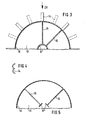
- FIG. 2 shows a cross section through a further embodiment of an immersion body, different variants for the design of the individual parts of the immersion body being shown in the individual quadrants.
- An unperforated inner tube 9 can be seen first, concentrically with the perforated outer tube 10 and again concentrically with this also a perforated blade tube 22.
- the inner tube 9 is filled with air. Since the inner tube 9 is constantly immersed in the wastewater, it provides additional buoyancy, which not only compensates for the weight of the inner tube 9 itself, but also for part of the weight of the rest of the construction. This relieves the load on the bearings and saves drive energy.
- Outer tube 10 and possibly blade tube 22 can be profiled in a wide variety of ways. Shown are, for example, S-shaped sheet metal tongues 12 bent out of the elongated holes 11 or also S-shaped sheet metal tongues 12 ', which are partly outside, partly inside the outer contour of the tubes 10, 22.
- the perforations of the tubes 10, 22 can also be designed differently.
- the perforations 11 are somewhat larger than the standing metal webs, the perforations 11 'are considerably larger than the standing metal webs and the perforations 11 "are as large as the metal webs.
- a suction or nozzle effect on the elongated holes arises, the air sucks under the water surface and divides it into the finest bubbles, and that this effect is considerably enhanced by the tongues 12, 12 '.
- the combined action of the outer contour of the immersion body and the centrifugal force creates a flow in the clarifier which pumps the waste water axially into the immersion body and radially out of the immersion body.
- 8 openings for example radial slots 21, are provided in the end plates.
- the size of the slots 21 and also the size of the perforations 11 in the outer tube 10 is to be matched to the size of the immersion bodies so that they cannot leave the space 13 between the inner tube 9 and the outer tube 10.
- the centrifugal force can be changed considerably - increased or decreased - by installing radial bulkheads 16, 16 ', 16 ".
- These bulkheads 16, 16', 16" which simultaneously divide the interior 13 into chambers, act in conjunction with the relative high peripheral speed of the immersion body like the wings of a centrifugal pump. This effect can be strengthened or weakened by suitable shaping of the bulkheads 16.
- FIG. 3 also shows in cross section a further embodiment for an immersion body with an inner tube 9 'and an outer tube 10.
- the space 13 between the two tubes is partitioned off with the aid of bulkheads 15, 16, the bulkheads 15 being perforated, the bulkheads 16 being unperforated .
- Blades 14 are attached to the outer tube, the cross section of which corresponds, for example, to the cross section of Pelton turbines, as shown in FIG. 4.
- These blades 14, either alone or in addition to the S-shaped tongues 12 featured air and kinetic energy can be seen in the wastewater. Instead of the blades 14, which must be attached individually, there is also the possibility of providing an additional tube as a blade tube for ventilation and movement.
- the bulkheads 15, 16 not only limit the movement space for the fillers, but at the same time stiffen the overall construction of the immersion body, which is particularly advantageous when the tubes 9 ', 10 are very long and have a small outside diameter.
- the inner tube 9 is designed as a polygonal sheet metal cylinder with continuous longitudinal slots. To form the longitudinal slots, the metal sheets of the inner tube 9" were not welded to one another or only at points. They are held by the bulkheads 15, 16 on the outer tube 10.
- the outer tube 10 can, as already described with reference to FIGS. 1 to 4, be equipped with blades 14 as well as with S-shaped tongues 12, 12 '. A blade tube 22 is also possible.
- Fig. 6 shows a graph in which in a rectangular coordinate system on the X axis, the speed V on the circumference of the outer tube 10 in m / s and on the Y axis, the specific biodegradation rate kg BOD 5 per kWh or the specific Oxygenation in kg 0 2 are also shown per kWh.
- the peripheral speed V increases, the specific oxygen input into the wastewater increases.
- the peripheral speed is currently on the market widespread immersion body specified, which corresponds approximately to the subject of DE-OS 27 27 991, while the surface aerators currently in use with a peripheral speed of 2.5 m / sec. work.
- the specific degradation capacity was entered in the diagram according to parameters, namely with 0.6 or 1.0 kg BOD 5 / kWh.
- the value of 1.0 kg BOD S / kWh corresponds to the system just mentioned according to DE-OS 27 27 991; the value 0.6 corresponds to the known activation processes with horizontal-axis surface aerators. These are mean values from various measurements. It is clear that the specific biodegradation power cannot be increased linearly with the drive power for the immersion body, since this is a biological process which is essentially dependent on the supply of oxygen on the one hand and nutrients, ie waste water on the other hand.
- the diagram shows that an optimal speed range V o p t is between 0.9 and 1.6 m / s.
- An optimal wastewater-air mixture can be used at peripheral speeds of up to 5 m / sec. to reach.
- the peripheral speed of the immersion body according to the invention is thus five to ten times higher than that of the currently customary immersion bodies.
- Fig. 7 shows a cross section through a filler 17, preferably made of plastic.
- a filler 17 preferably made of plastic.
- the diameter of such a packing 17 is approximately 5 cm.
- the width of the webs 18 must at least be greater than the width of the interstices 19 at least on the spherical surface and only partially there.
- a major advantage of the invention in addition to the already mentioned increased biodegradation capacity is that the immersion body drum can be built in practically any length. Spans between the bearings of five to ten meters are conceivable. This is possible by dispensing with a continuous central axis, on which the other construction is attached.
- the selected construction of tube and inner tube enables the deflection between the axle bearings to be limited to a reasonable value by appropriate choice of sheet thickness and tube diameter, whereby these values can be increased even further by using an air-filled inner tube.
Abstract
Description
Die Erfindung betrifft eine mechanisch-biologische Kläranlage zum Reinigen von Abwässern, mit einem in das Abwasser eintauchenden, rotierenden Tauchkörper, der ein gelochtes Außenrohr aufweist und mit Schüttgut als Bewuchskörper für biologischen Rasen gefüllt ist. Sie betrifft ferner ein Verfahren zum Klären von Abwässern unter Anwendung dieser Vorrichtung.The invention relates to a mechanical-biological sewage treatment plant for the purification of waste water, with a rotating immersion body immersed in the waste water, which has a perforated outer tube and is filled with bulk material as a fouling element for biological turf. It also relates to a method for treating waste water using this device.
Kläranlagen mit derartigen Tauchkörpern sind bekannt. Allerdings werden sie seit längerem nicht mehr verwendet, da das Schüttgut unverhältnismäßig schnell verschlammt, worauf die Anlage vom aeroben zum anaeroben Schlammabbau übergeht. Das darf in einer guten Kläranlage jedoch nicht passieren.Sewage treatment plants with such immersion bodies are known. However, they have not been used for a long time since the bulk material silted up disproportionately quickly, whereupon the plant changed from aerobic to anaerobic sludge degradation. However, this must not happen in a good sewage treatment plant.
Ein weiterer Nachteil derartiger Kläranlagen ist die Tatsache, daß sich der Schlamm leicht in den Ecken des Klärbeckens absetzen kann. Um zu verhindern, daß dieser Schlamm anaerob abgebaut wird, muß er ständig in Bewegung gehalten werden. Hierzu werden besondere Aggregate benötigt. Die CH-PS 50 963 zeigt einen Tauchkörper, der koaxial eine antreibbare Welle und im Abstand von dieser ein gelochtes Außen- und ein gelochtes Innenrohr besitzt. Der Raum zwischen den beiden Rohren ist mit Schüttgut gefüllt, welches als Bewuchskörper für den biologischen Rasen dient. Dieser bekannte Tauchkörper rotiert zu etwa einem Drittel im Abwasser eingetaucht. Im aufgetauchten Zustand sättigt sich der biologische Rasen mit Luftsauerstoff und trägt diesen im eingetauchten-Zustand in das Abwasser ein. Die Montage derartiger Tauchkörper am Einsatzort ist schwierig. Außerdem verschlammen sie auch leicht und das Abwasser beginnt zu stinken.Another disadvantage of such treatment plants is the fact that the sludge can easily settle in the corners of the clarifier. To prevent this sludge from being broken down anaerobically, it must be kept in motion. Special units are required for this. The CH-PS 50 963 shows an immersion body, which coaxially has a drivable shaft and at a distance from it a perforated outer and a perforated inner tube. The space between the two pipes is filled with bulk material, which serves as a growth element for the organic lawn. This known immersion body rotates about a third immersed in the wastewater. In the submerged state, the biological lawn saturates with atmospheric oxygen and, when submerged, enters it into the wastewater. The assembly of such immersion bodies on site is difficult. They also silt up slightly and the wastewater begins to stink.
Aus der DE-AS 18 15 001 ist ein weiterer Tauchkörper bekannt, der aus mehreren ring-, sektor- oder würfelförmigen Teilkörpern gebildet ist, die ringförmig aneinander gereiht um die koaxiale, angetriebene Welle herum angeordnet sind. In jedem Teilkörper befindet sich ein Stapel aus einzelnen, in Schichten aufeinander gelegten Platten aus Kunststoff mit beispielsweise wellenförmiger Oberfläche. Die Platten dienen als Bewuchskörper für den biologischen Rasen. Die Platten sind senkrecht zur Welle angeordnet, so daß beim Auftauchen aus dem Abwasser die Abwasserreste schnell von der Plattenoberfläche ablaufen können. Auch dieser Tauchkörper wird nur zu etwa einem Drittel seines Durchmessers in das Abwasser eingetaucht.From
Eine weitere Einrichtung für die mechanisch-biologische Reinigung von Abwassern ist bekannt aus der DE-AS 11 84 286. Es handelt sich dabei um eine waagerecht drehbare Be- lüftungstrommel, die mit speziellen Füllkörpern gefüllt ,ist. Das -u reinigende Abwasser wird am einen Ende der Trommel eingeleitet und mit Hilfe von spiraligen Leitflächen zum anderen Ende der Trommel gefördert. Die Füllkörper, die den Innenraum der Trommel beispielsweise vollständig ausfüllen, haben die Form von Schöpfgefäßen. Sie nehmen deshalb eine bestimmte Menge von Abwasser auf und transportieren es nach oben, wo es ausgeschüttet wird und langsam durch die Trommel nach unten rieselt. Dabei kommt es in innigen Kontakt mit dem biologischen Rasen, der sich auf den Füllkörpern gebildet hat. Auch bei dieser Art von Kläranlage ist ein großer Teil der biologisch aktiven Oberfläche nicht an der Klärung des Abwassers beteiligt.A further device for mechanical-biological purification of waste water is known from DE-AS 11 84 286. This is about a horizontally rotatable loading drum ventilation t being filled with special filling bodies is. The -u cleaning wastewater is introduced at one end of the drum and with the help of a spiral pipe surfaces promoted to the other end of the drum. The fillers, which completely fill the interior of the drum, for example, have the shape of scoops. They therefore take up a certain amount of waste water and transport it upwards, where it is poured out and slowly trickles down through the drum. It comes into intimate contact with the organic lawn that has formed on the packing. In this type of wastewater treatment plant, too, a large part of the biologically active surface is not involved in the wastewater treatment.
Eine weitere Ausführungsform von trommelförmigen Tauchkörpern ist aus den DE-OSen 26 38 665 bzw. 27 27 991 bekannt. Diese Offenlegungsschriften zeigen unter anderem einen Tauchkörper mit einer zentralen, angetriebenen Achse, auf der ein abschnittsweise gelochtes Rohr befestigt ist. Das Innere des Tauchkörpers ist mit Hilfe von gebogenen, ungelochten Schotten in Kammern eingeteilt. Als Bewuchskörper für den biologischen Rasen dienen hier wieder Stapel von aufeinandergelegten Platten aus Kunststoff mit geeignet ausgebildeter Oberfläche. Auch dieser Tauchkörper ist nur zu etwa einem Drittel in das Abwasser eingetaucht.Another embodiment of drum-shaped immersion bodies is known from DE-OS 26 38 665 or 27 27 991. These published documents show, among other things, an immersion body with a central, driven axis, on which a sectioned tube is attached. The inside of the immersion body is divided into chambers with the help of curved, unperforated bulkheads. Again, stacks of superimposed plastic plates with a suitably designed surface serve as vegetation bodies for the organic turf. Only about a third of this immersion body is immersed in the wastewater.
Die abschnittsweise Lochung des Außenrohres und die Ausgestaltung und Anordnung der Schottenwände sind so aufeinander abgestimmt, daß beim Eintauchen der Kammern in das Abwasser eine gewisse Menge Luft mit unter Wasser genommen wird. Diese Luft beginnt durch die Lochungen des Außenrohres auszuströmen, sobald die Kammer ihre unterste Stellung überschritten hat. Hierdurch erfolgt zwar eine gewisse Sauerstoffanreicherung des Abwassers im Klärbecken selbst; der in die Luftblase eintauchende Teil der Bewuchskörper nimmt jedoch an der Abwasserreinigung nicht teil, solange die Luft nicht aus der Kammer ausgeströmt ist. Aus diesem Grund ist die biologische Abbauleistung einer Kläranlage mit einem solchen Tauchkörper nicht höher als die der zuvor beschriebenen Anlagen.The section-wise perforation of the outer pipe and the design and arrangement of the bulkhead walls are coordinated so that a certain amount of air is taken under water when the chambers are immersed in the waste water. This air begins to flow out through the perforations in the outer tube as soon as the chamber has passed its lowest position. This does indeed result in a certain oxygen enrichment of the wastewater in the clarifier itself; however, the part of the vegetation dipping into the air bubble takes part in the sewage drain Do not take part until the air has escaped from the chamber. For this reason, the biological degradation performance of a sewage treatment plant with such an immersion body is not higher than that of the plants described above.
Eine weitere Art von Tauchkörpern für mechanisch-biologische Kläranlagen ist bekannt aus der DE-PS 29 11 975. Hier besteht der Tauchkörper aus einer zentralen Hohlwelle, auf der mittels Schotten eine aus Blechtafeln gebildete polygonale Trommel befestigt ist, so daß im Inneren der Trommel eine Reihe von Kammern gebildet werden. Diese Kammern sind mit in Schichten aufeinandergelegten Platten aus Kunststoff mit geeigneter Oberfläche gefüllt. Schlitze in der Außentrommel sind so angeordnet, daß beim Eintauchen einer Kammer in das Abwasser eine größere Menge Luft mitgenommen wird. Mit Hilfe von zusätzlichen Trennwänden wird hier dafür gesorgt, daß diese Luft innerhalb der Kammer umgewälzt wird. Ferner ist die Hohlwelle mit einzelnen Durchbrechungen ausgerüstet, so daß die in den Kammern eingeschlossene Luft aus den unteren Kammern in die Hohlwelle und aus der Hohlwelle in die oberen Kammern strömen kann. Auch bei dieser Ausführungsform nimmt der Teil der Bewuchskörper, der momentan in die Luftblase hineinragt, nicht an der Abwasserreinigung teil; da die Luft hier jedoch auch durch die Hohlwelle abströmen kann, ist die Abbauleistung etwas besser als bei der zuvor beschriebenen Anlage.Another type of immersion bodies for mechanical-biological sewage treatment plants is known from DE-PS 29 11 975. Here, the immersion body consists of a central hollow shaft on which a polygonal drum made of sheet metal plates is fastened by means of bulkheads, so that a inside the drum Series of chambers are formed. These chambers are filled with plastic plates with a suitable surface that are stacked on top of one another. Slots in the outer drum are arranged so that when a chamber is immersed in the waste water, a larger amount of air is taken along. With the help of additional partition walls, it is ensured that this air is circulated within the chamber. Furthermore, the hollow shaft is equipped with individual openings, so that the air enclosed in the chambers can flow from the lower chambers into the hollow shaft and from the hollow shaft into the upper chambers. In this embodiment too, the part of the fouling element which currently projects into the air bubble does not take part in the wastewater treatment; however, since the air can also flow through the hollow shaft here, the degradation performance is slightly better than in the system described above.
Eine Abwandlung der soeben beschriebenen Anlage zeigt die DE-OS 31 09 184. Hier sind an der Außenseite der polygonalen Trommel zusätzliche Kammern angeordnet, in denen zusätzliche Luftmengen unter den Abwasserspiegel mitgenommen werden können. Die in diesen zusätzlichen Kammern eingeschlossene Luft kann nach Überschreiten des unteren Totpunktes teilweise in das Abwasser abströmen. Da diese Luft jedoch nicht in Berührung mit den plattenförmigen Bewuchskörpern kommt, ist eine Verbesserung der biologischen Abbauleistung praktisch nicht meßbar.DE-OS 31 09 184 shows a modification of the system just described. Here, additional chambers are arranged on the outside of the polygonal drum, in which additional air volumes below the waste water level can be taken. The air enclosed in these additional chambers can partially flow into the waste water after the bottom dead center has been exceeded. However, since this air does not come into contact with the plate-shaped growth bodies, there is practically no measurable improvement in the biodegradation performance.
Der geschilderte Stand der Technik läßt erkennen, daß vielfach versucht wurde, zusätzliche Luftmengen in das Abwasser einzutragen und gleichzeitig die Tauchkörper tiefer in das Abwasser eintauchen zu lassen, daß diese Versuche aber dieses Ziel nicht oder nur zu einem ganz geringen Teil erreichten konnten. Von wesentlicher Bedeutung ist dabei unter anderem auch der spezifische Energieverbrauch, d.h. das Verhältnis von biologischer Abbauleistung zu mechanischer Antriebsleistung. Da mit den eingangs geschilderten Anlagen diese Ziele nicht erreicht werden konnten, sind heute andere Arten von Tauchkörpern üblich. Es handelt sich dabei um eine Vielzahl von zylindrischen Teilkörpern, die mit den bekannten, in Schichten aufeinandergelegten Platten aus Kunststoff mit geeigneter Oberfläche gefüllt sind und mit Hilfe von speichenartigen Streben an einer zentralen Antriebswelle befestigt sind. Die Teilkörper dieser Tauchkörper sind entweder ganz aus dem Abwasser ausgetaucht oder ganz in das Abwasser eingetaucht, wobei auch hier wieder durch entsprechende Teillochung der Außenhaut Luft mit in das Abwasser eingetragen wird. Diese heute überwiegend verwendeten Ausführungsformen von Tauchkörpern sind neben den oben beschriebenen Ausführungsformen ebenfalls in den DE-OS 26 38 665 bzw. 27 27 991 dargestellt.The described prior art shows that many attempts have been made to introduce additional amounts of air into the wastewater and at the same time to have the immersed body immersed deeper into the wastewater, but that these attempts were unable to achieve this goal or only to a very small extent. Among other things, the specific energy consumption, i.e. the ratio of biodegradation power to mechanical drive power. Since these goals could not be achieved with the systems described at the beginning, other types of immersion bodies are common today. These are a large number of cylindrical partial bodies which are filled with the known plastic layers with a suitable surface layered on top of one another and are fastened to a central drive shaft with the aid of spoke-like struts. The sub-bodies of these immersion bodies are either completely immersed in the wastewater or completely immersed in the wastewater, air being introduced into the wastewater again here by appropriate partial perforation of the outer skin. These mainly used embodiments of immersion bodies are also shown in DE-OS 26 38 665 and 27 27 991 in addition to the embodiments described above.
Der vorliegenden Erfindung liegt die Aufgabe zugrunde, eine mechanisch-biologische Kläranlage der eingangs beschriebenen Art anzugeben, die bei einfachster mechanischer Konstruktion für kleine und große Anlagen einsetzbar ist, die den Eintrag von Sauerstoff sowie Bewegungsenergie in das Abwasser mit verbessertem Wirkungsgrad ermöglicht und dabei eine erhöhte Klärwirkung bzw. eine größere Belastbarkeit ermöglicht.The present invention has for its object to provide a mechanical-biological sewage treatment plant of the type described above, which can be used with the simplest mechanical design for small and large plants, which enables the entry of oxygen and kinetic energy into the wastewater with improved efficiency and thereby increased Clarification effect or greater resilience enables.
Diese Aufgabe wird dadurch gelöst, daß konzentrisch zum Außenrohr ein Innenrohr angeordnet ist, daß Innenrohr und Außenrohr über Stirnbleche miteinander und mit Achszapfen verbunden sind, daß das Außenrohr an seiner Außenseite derart profiliert ist, daß bei rotierendem Tauchkörper ein innig verwirbeltes Abwasser-Luft-Gemisch im Klärbecken entsteht, und daß der Tauchkörper mit Füllkörpern gefüllt ist, die eine große innere Oberfläche besitzen und deren Konturen so ausgebildet sind, daß das Abwasser-Luft-Gemisch zwischen den Füllkörpern hindurchströmen kann.This object is achieved in that an inner tube is arranged concentrically with the outer tube, that the inner tube and outer tube are connected to one another and with axle journals via end plates, that the outer tube is profiled on its outside in such a way that an intimately swirled wastewater / air mixture when the immersion body rotates arises in the clarifier, and that the immersion body is filled with packing elements which have a large inner surface and whose contours are designed in such a way that the wastewater-air mixture can flow between the packing elements.
Die Bezeichnung Außenrohr soll verdeutlichen, daß dieses Rohr den Raum, in dem die den biologischen Rasen tragenden Füllkörper sich befinden, nach außen, d.h. gegen das Klärbecken begrenzt.The designation outer tube is intended to make it clear that this tube is the space in which the filling bodies carrying the organic turf are located, i.e. limited against the clarifier.
Die zusätzliche Anordnung eines Innenrohres begrenzt den den Füllkörpern zur Verfügung stehenden Raum, z.B. dann, wenn im Zentrum des Rotors ein biologischer Abbau mangels Sauerstoff nicht zu erwarten ist.The additional arrangement of an inner tube limits the space available to the packing, e.g. then, if a biodegradation due to lack of oxygen is not to be expected in the center of the rotor.
Ein wesentlicher Vorteil der erfindungsgemäßen Konstruktion besteht in der hohen Stabilität des Tauchkörpers. Obwohl sowohl die Rohre als auch die Stirnbleche nur aus relativ dünnwandigen Blechen bestehen, die zudem noch durchbrochen sein können, kann der rotierende Tauchkörper ohne weiteres Baulängen von bis zu 10 m erhalten, ohne daß Festigkeitsprobleme entstehen.A major advantage of the construction according to the invention is the high stability of the immersion body. If Probably both the tubes and the end plates consist only of relatively thin-walled plates, which may also be broken, the rotating immersion body can easily be up to 10 m long without any strength problems.
Weiterhin kann konzentrisch zum Außenrohr ein sogenanntes Schaufelrohr vorgesehen sein. Dieses Schaufelrohr unterstützt das Einbringen von Luft und Bewegung in das Abwasser und hat den Vorteil der einfacheren Herstellung gegenüber dem Anbringen von einzelnen, turbinenähnlichen Schaufeln außen am Außenrohr.Furthermore, a so-called blade tube can be provided concentrically with the outer tube. This blade tube supports the introduction of air and movement into the wastewater and has the advantage of simpler manufacture compared to the attachment of individual, turbine-like blades on the outside of the outer tube.
Die vorliegende Erfindung vermeidet weitgehend die bei den bisherigen Kläranlagen zu unterscheidenden Arbeitsphasen: Auftauchphase für die Sauerstoffanreicherung und Eintauchphase für den biologischen Abbau. Der rotierende Tauchkörper erzeugt vielmehr ein innig verwirbeltes Abwasser-Luft-Gemisch im Klärbecken, so daß der auf den Füllkörpern wachsende biologische Rasen sich ständig in einem Medium aufhält, welches sowohl Sauerstoffanreicherung als auch biologischen Abbau ermöglicht. Hierdurch ergibt sich die Möglichkeit, die Füllkörper des Tauchkörpers fast ständig unterhalb des Wasserspiegels im Klärbecken zu halten. Das bedeutet, daß der Tauchkörper vollständig untergetaucht bleiben kann. In der Praxis bleibt ein Teil des Tauchkörperraums über dem Wasserspiegel, da sich gezeigt hat, daß die Tauchkörper so erhebliche Mengen von Luft mitnehmen.The present invention largely avoids the work phases to be distinguished in the previous sewage treatment plants: ascent phase for oxygen enrichment and immersion phase for biodegradation. Rather, the rotating immersion body creates an intimately swirled wastewater-air mixture in the clarifier, so that the biological lawn growing on the packing elements is constantly in a medium that enables both oxygenation and biodegradation. This results in the possibility of keeping the fillers of the immersion body almost constantly below the water level in the clarifier. This means that the immersion body can remain completely submerged. In practice, part of the immersion body space remains above the water level, since it has been shown that the immersion bodies take considerable amounts of air with them.
Um das verwirbelte Abwasser-Luft-Gemisch zu erzeugen, muß der Tauchkörper mit einer erheblich größeren Drehzahl rotieren als die derzeit verwendeten Tauchkörper. Dies gibt gleichzeitig die Möglichkeit, in das Abwasser eine erhöhte Bewegungsenergie einzuleiten, wodurch das Absetzen von Klärschlamm auch bei großen Becken verhindert und eine größere Verweilzeit des Abwassers erreicht wird, was wiederum für die erhöhte Klärwirkung bzw. die erhöhte Belastbarkeit der Anlage günstig ist.In order to generate the swirled wastewater-air mixture, the immersion body must rotate at a considerably higher speed than the immersion bodies currently used. This At the same time, it gives the option of introducing increased kinetic energy into the wastewater, thereby preventing sewage sludge from settling even in large pools and increasing the dwell time of the wastewater, which in turn is beneficial for the increased clarification effect and the increased load capacity of the system.
Es ist leicht einzusehen, daß die mit der Erfindung zu erreichenden Vorteile naturgemäß durch eine besondere Konstruktion der Füllkörper noch unterstützt werden. Sie ermöglicht einerseits eine große Menge von biologischem Rasen, verhindert andererseits ein Verschlammen, da zwischen den einzelnen Füllkörpern ausreichend Platz für durchströmendes Abwasser bleibt.It is easy to see that the advantages to be achieved with the invention are naturally supported by a special construction of the packing. On the one hand, it enables a large amount of organic lawn, on the other hand it prevents silting up, as there is enough space between the individual packing elements for wastewater to flow through.
Die Füllkörper besitzen vorzugsweise eine Kugelform mit einer Reihe von Stegen, die durch Zwischenräume voneinander getrennt sind, wobei Form und Abmessung so gewählt sind, daß benachbarte Füllkörper nicht ineinander verhaken, andererseits aber das Abwasser-Luft-Gemisch einwandfreien Zutritt zum biologischen Rasen hat.The fillers preferably have a spherical shape with a series of webs which are separated from one another by gaps, the shape and dimensions being selected such that adjacent fillers do not get caught in one another, but on the other hand the wastewater / air mixture has perfect access to the organic lawn.
Um bei minimaler Antriebsleistung einen maximalen Eintrag von Sauerstoff und Bewegungsenergie in das Abwasser zu erzielen, kann gemäß einer vorteilhaften Weiterbildung das Außenrohr mit Schaufeln ähnlich Turbinenschaufeln bestückt sein.In order to achieve a maximum input of oxygen and kinetic energy into the wastewater with a minimum drive power, according to an advantageous development the outer tube can be equipped with blades similar to turbine blades.
Gemäß einer weiteren Ausgestaltung sind die Lochungen im Außenrohr als Langlöcher ausgebildet und die aus den Langlöchern ausgestanzten Blechteile - in Drehrichtung des Tauchkörpers - S-förmig über die Kontur des Außenrohres herausgebogen. Diese Konstruktion erlaubt eine optimale Materialausnutzung. Um einen möglichst guten Zugang des Abwasser-Luft-Gemisches zum biologischen Rasen zu ermöglichen, müssen die Lochungen insbesondere im Außenrohr möglichst großflächig gewählt werden. Die Abmessungen sind lediglich durch die Abmessungen der Füllkörper begrenzt.According to a further embodiment, the perforations in the outer tube are designed as elongated holes and the sheet metal parts punched out of the elongated holes are bent out in an S shape over the contour of the outer tube in the direction of rotation of the immersion body. This construction allows one optimal material utilization. In order to allow the wastewater-air mixture to have the best possible access to the organic lawn, the perforations, in particular in the outer pipe, must be chosen to be as large as possible. The dimensions are only limited by the dimensions of the packing.
Gemäß einer vorteilhaften Weiterbildung ist das Innenrohr mit Luft gefüllt.Es erzeugt auf diese Weise einen Auftrieb, der nicht nur das Gewicht des Innenrohrs selbst sondern auch einen Teil des Gewichts der übrigen Konstruktion kompensiert. Die Größe dieses Auftriebs ist abhängig vom Durchmesser des Innenrohrs, wobei ein Kompromiß gefunden werden muß zwischen der Größe des Auftriebs und der Größe des für die Füllkörper noch zur Verfügung stehenden Raums zwischen Innenrohr und Außenrohr.According to an advantageous further development, the inner tube is filled with air. In this way, it generates a buoyancy that not only compensates for the weight of the inner tube itself but also for part of the weight of the rest of the construction. The size of this buoyancy depends on the diameter of the inner tube, whereby a compromise must be found between the size of the buoyancy and the size of the space between the inner tube and the outer tube still available for the packing.
Das besondere an dem unter Verwendung der erfindungsgemäßen Kläranlage arbeitenden Klärverfahren ist also die hohe Produktionsgeschwindigkeit am Umfang des Außenrohrs bzw. gegebenenfalls des Schaufelrohrs, die so hoch ist, daß im Klärbecken ein innig verwirbeltes und durchmischtes Abwasser-Luft-Gemisch entsteht, in dem die den biologischen Rasen tragenden Bewuchskörper ständig bewegt werden. Aufgrund dieser Besonderheit kann der mit Bewuchskörpern gefüllte Raum des Tauchkörpers praktisch vollständig unterhalb der Wasserlinie rotieren. Läßt man den mit Bewuchskörpern gefüllten Raum wenigstens teilweise auftauchen, so dienen die Bewuchskörper selbst als Schaufelelemente, die eine erhebliche Menge an Luftsauerstoff mit in das Abwasser eintragen. So zeigt die Erfahrung, daß noch lange nach Abstellen der Drehbewegung Luftblasen aus den Bewuchskörpern hochsteigen. Auch wenn diese Blasenbildung zur Ruhe gekommen ist, enthalten die Bewuchskörper noch erhebliche Mengen an Luft, die bei einem vorsichtigen Weiterdrehen des Tauchkörpers ausperlt. Solange jedoch dem biologischen Rasen sowohl Abwasser als auch Luft zur Verfügung stehen, wird der Klärschlamm abgebaut.The special thing about the treatment process using the sewage treatment plant according to the invention is the high production speed on the circumference of the outer tube or, if necessary, the shovel tube, which is so high that an intimately swirled and mixed wastewater-air mixture is created in the clarifier, in which the biological lawn-bearing vegetation bodies are constantly moved. Due to this special feature, the space of the immersion body filled with vegetation bodies can practically rotate completely below the water line. If the space filled with fouling bodies is at least partially exposed, the fouling bodies themselves serve as scoop elements which also carry a considerable amount of atmospheric oxygen into the waste water. Experience shows that long after turning off the shoot movement Air bubbles rise out of the vegetation. Even if this bubble formation has come to rest, the growth bodies still contain considerable amounts of air, which also bubbles out when the T is turned gently. However, as long as both wastewater and air are available to the organic lawn, the sewage sludge is broken down.
Weitere Ausgestaltungen der Erfindung sowie deren Vorteile ergeben sich aus den weiteren Unteransprüchen sowie der nachfolgenden Beschreibung von Ausführungsbeispielen anhand der Zeichnung. Es zeigen
- Fig. 1 einen Querschnitt durch ein Klärbecken mit einem teilweise geschnittenen und gebrochenen Tauchkörper,
- Fig. 2 einen Querschnitt durch einen Tauchkörper mit unterschiedlichen Konstruktionsdetails,
- Fig. 3 einen Querschnitt durch eine weitere Ausführungsform eines Tauchkörpers,
- Fig. 4 einen Querschnitt durch eine Schaufel, mit der der Tauchkörper bestückt wird,
- Fig. 5 einen Querschnitt durch eine weitere Ausführungsform eines Tauchkörpers,
- Fig. 6 ein Schaubild zur Darstellung des Zusam - menhangs zwischen Drehgeschwindigkeit des Tauchkörpers, dem leistungsspezifischen Sauerstoffeintrag ins Abwasser und der leistungsspezifischen biologischen Abbauleistung und
- Fig. 7 einen Querschnitt durch einen Füllkörper.
- 1 shows a cross section through a clarifier with a partially cut and broken immersion body,
- 2 shows a cross section through an immersion body with different construction details,
- 3 shows a cross section through a further embodiment of an immersion body,
- 4 shows a cross section through a blade with which the immersion body is fitted,
- 5 shows a cross section through a further embodiment of an immersion body,
- 6 shows a diagram to illustrate the relationship between the speed of rotation of the immersion body and the performance-specific oxygen input into the waste water and the performance-specific biodegradation performance and
- Fig. 7 shows a cross section through a packing.
In Fig. 1 erkennt man einen Querschnitt durch eine Kläranlage 1 mit Klärbecken 2. Am Rand des Klärbeckens sind auf halber Höhe Lager 3 befestigt. In den Lagern 3 laufen Achszapfen 4, die die Verbindung zu dem eigentlichen Tauchkörper herstellen, der aus einem gelochten Innenrohr 9 und einem gelochten Außenrohr 10 besteht, welche stirnseitig über Stirnbleche 8 miteinander und mit den Achszapfen 4 verbunden sind. Auf dem linken Achszapfen 4 ist eine Antriebsscheibe 5 montiert, auf der ein Antriebsmittel 6, beispielsweise eine Kette läuft, welche die Antriebsenergie eines Getriebemotors 7 auf den Achszapfen 4 und damit auf den Tauchkörper 8, 9, 10 überträgt.1 shows a cross section through a
Das Innenrohr 9 besteht aus Blech, welches durch Ausstanzungen eine Gitterform erhalten hat. Damit wird ein optimaler Durchtritt von Abwasser bzw. Abwasser-Luft-Gemisch erreicht.The inner tube 9 consists of sheet metal, which has been given a lattice shape by punching. This ensures an optimal passage of wastewater or wastewater / air mixture.
Das Außenrohr 10 ist mit einer regelmäßigen Anordnung von Langlöchern 11 versehen. Das aus den Langlöchern ausgestanzte Blechmaterial ist S-förmig über die Außenkontur des Außenrohres 10 herausgebogen, wie bei Fig. 2 besser zu sehen ist. Diese S-förmigen Metallzungen 12 bilden Schaufeln, die das Abwasser in Bewegung versetzen, wodurch ein Absetzen von Klärschlamm am Boden des Beckens 2 verhindert wird, und tragen bei ausreichender Drehzahl Luft-Sauerstoff in das Abwasser ein.The
Wie aus Fig. 1 weiterhin zu sehen ist, taucht der Tauchkörper so weit in das Abwasser ein, daß das Außenrohr 10, das mit Füllkörpern gefüllt ist, annähernd vollständig im Abwasser rotiert. Durch das Eintragen von großen Mengen Luft in das Abwasser durch Erzeugen des Abwasser-Luft-Gemisches kann auf die bisher übliche Unterscheidung zwischen Auftauchphase und Eintauchphase nahezu verzichtet werden.As can also be seen from FIG. 1, the immersion body dips into the wastewater to such an extent that the
Die durchgeführten Versuche haben gezeigt, daß der Wasserspiegel dort, wo der Tauchkörper aus dem Abwasser auftaucht, höher steigt als im übrigen Becken. Durch die spezielle Formgebung des Tauchkörpers sowie durch die Zentrifugalkraft entsteht eine Strömung, die Luft und Abwasser aus dem Becken axial in den Tauchkörper und damit zu den Füllkörpern bzw. zu dem biologischen Rasen pumpt.The tests carried out have shown that the water level where the immersion body emerges from the waste water rises higher than in the rest of the pool. The special shape of the immersion body and the centrifugal force create a flow that pumps air and wastewater axially out of the pool into the immersion body and thus to the packing elements or to the biological lawn.
In Fig. 2 erkennt man einen Querschnitt durch eine weitere Ausführungsform eines Tauchkörpers, wobei in den einzelnen Quadranten unterschiedliche Varianten für die Gestaltung der Einzelteile des Tauchkörpers dargestellt sind. Man erkennt zunächst ein ungelochtes Innenrohr 9, konzentrisch dazu das gelochte Außenrohr 10 und wiederum konzentrisch hierzu ein ebenfalls gelochtes Schaufelrohr 22. Das Innenrohr 9 ist mit Luft gefüllt. Da das Innenrohr 9 ständig in das Abwasser eingetaucht ist, liefert es einen zusätzlichen Auftrieb, der nicht nur das Gewicht des Innenrohrs 9 selbst, sondern auch einen Teil des Gewichts der übrigen Konstruktion kompensiert. Dadurch werden die Lager entlastet und Antriebsenergie eingespart.2 shows a cross section through a further embodiment of an immersion body, different variants for the design of the individual parts of the immersion body being shown in the individual quadrants. An unperforated inner tube 9 can be seen first, concentrically with the perforated
Außenrohr 10 und gegebenenfalls Schaufelrohr 22 können in den unterschiedlichsten Arten profiliert sein. Dargestellt sind beispielsweise S-förmige, aus den Langlöchern 11 herausgebogene Blechzungen 12 oder auch S-förmig gebogene Blechzungen 12', die teilweise außerhalb, teilweise innerhalb der Außenkontur der Rohre 10, 22 liegen.
Auch die Lochungen der Rohre 10,22 können unterschiedlich gestaltet sein. So sind die Lochungen 11 etwas größer als die stehenbleibenden Metallstege, die Lochungen 11' erheblich größer als die stehenbleibenden Metallstege und die Lochungen 11" ebenso groß wie die Metallstege. Die Erfahrung hat gezeigt, daß bei ausreichender Umfangsgeschwindigkeit ein Sog- oder Düseneffekt an den Langlöchern entsteht, der Luft unter die Wasseroberfläche saugt und diese in feinste Blasen zerteilt, und daß dieser Effekt durch die Zungen 12, 12' noch erheblich verstärkt wird.The perforations of the
Wie schon vorstehend erwähnt, entsteht im Klärbecken durch die gemeinsame Wirkung der Außenkontur des Tauchkörpers und der Zentrifugalkraft eine Strömung, die das Abwasser axial in den Tauchkörper hinein und radial aus dem Tauchkörper heraus pumpt. Um diese Strömung zu ermöglichen, sind in den Stirnblechen 8 Öffnungen, beispielsweise radiale Schlitze 21, vorgesehen.As already mentioned above, the combined action of the outer contour of the immersion body and the centrifugal force creates a flow in the clarifier which pumps the waste water axially into the immersion body and radially out of the immersion body. In order to enable this flow, 8 openings, for example
Die Größe der Schlitze 21 und ebenso die Größe der Lochungen 11 im Außenrohr 10 ist auf die Größe der Tauchkörper so abzustimmen, daß diese den Raum 13 zwischen Innenrohr 9 und Außenrohr 10 nicht verlassen können. Die Zentrifugalkraft kann erheblich verändert - verstärkt oder verringert - werden durch den Einbau von radialen Schotten 16, 16', 16". Diese Schotten 16, 16', 16", die den Innenraum 13 gleichzeitig in Kammern unterteilen, wirken in Verbindung mit der relativ hohen Umfangsgeschwindigkeit des Tauchkörpers wie die Flügel einer Kreiselpumpe. Durch geeignete Formgebung der Schotten 16 kann dieser Effekt verstärkt oder abgeschwächt werden. Sind die Schotten 16' in Drehrichtung konvex, so wird die Wirkung verstärkt, wobei gleichzeitig der Widerstandswert verringert wird; sind die Schotten 16" in Drehrichtung konkav, so kann bei geeigneter Winkelstellung die nach außen gerichtete Zentrifugalkraft durch die nach innen gerichtete Schaufelkraft verringert werden.The size of the
Im Zusammenhang mit der Pumpwirkung der Schotten 16,16' dürfte es von Vorteil sein, auch das Innenrohr wasserdurchlässig zu gestalten. Auf diese Weise kann das Abwasser durch das Innenrohr 9 zentral zugeführt und anschließend radial durch den von den Füllkörpern gefüllten Raum 13 nach außen gepumpt werden.In connection with the pumping action of the
Fig. 3 zeigt ebenfalls im Querschnitt eine weitere Ausführungsform für einen Tauchkörper mit Innenrohr 9' und Außenrohr 10. Der Raum 13 zwischen den beiden Rohren ist mit Hilfe von Schotten 15, 16 abgeteilt, wobei die Schotten 15 gelocht, die Schotten 16 ungelocht sein können. Am Außenrohr sind Schaufeln 14 befestigt, deren Querschnitt beispielsweise dem Querschnitt von Pelton-Turbinen entspricht, wie in Fig. 4 dargestellt ist. Diese Schaufeln 14, die entweder allein oder auch zusätzlich zu den S-förmig gebogenen Zungen 12 vorgesehen sein können, tragen Luft und Bewegungsenergie in das Abwasser ein. Anstelle der Schaufeln 14, die einzeln angebracht werden müssen, besteht auch die Möglichkeit, ein zusätzliches Rohr als Schaufelrohr für die Belüftung und Bewegung vorzusehen.3 also shows in cross section a further embodiment for an immersion body with an inner tube 9 'and an
Die Schotten 15,16 begrenzen nicht nur den Bewegungsraum für die Füllkörper, sondern versteifen gleichzeitig die Gesamtkonstruktion des Tauchkörpers, was insbesondere dann von Vorteil ist, wenn es sich um sehr lange Rohre 9', 10 mit geringem Außendurchmesser handelt.The
Fig. 5 zeigt eine weitere Ausführungsform für einen Tauchkörper im Querschnitt. Hier ist das Innenrohr 9" als polygonaler Blechzylinder ausgebildet mit durchgehenden Längsschlitzen. Zur Bildung der Längsschlitze wurden die Blechtafeln des Innenrohres 9" nicht bzw. nur punktweise miteinander verschweißt. Sie werden durch die Schotten 15, 16 am Außenrohr 10 gehalten. Das Außenrohr 10 kann, wie anhand der Fig. 1 bis 4 bereits beschrieben, sowohl mit Schaufeln 14 als auch mit S-förmig gebogenen Zungen 12, 12' bestückt sein. Auch ein Schaufelrohr 22 ist möglich.5 shows a further embodiment for an immersion body in cross section. Here, the inner tube 9 "is designed as a polygonal sheet metal cylinder with continuous longitudinal slots. To form the longitudinal slots, the metal sheets of the inner tube 9" were not welded to one another or only at points. They are held by the
Fig. 6 zeigt ein Schaubild, bei dem in einem rechtwinkeligen Koordinatensystem auf der X-Achse die Geschwindigkeit V am Umfang des Außenrohres 10 in m/s und auf der Y--Achse die spezifische biologische Abbauleistung kg BSB5 pro kWh bzw. der spezifische Sauerstoffeintrag in kg 02 ebenfalls pro kWh dargestellt sind. Mit zunehmender Umfangsgeschwindigkeit V steigt der spezifische Sauerstoffeintrag ins Abwasser. Mit dem Wert 0,17 ist die Umfangsgeschwindigkeit eines derzeit am Markt weitverbreiteten Tauchkörpers angegeben, der etwa dem Gegenstand der DE-OS 27 27 991 entspricht, während die heute gebräuchlichen Oberflächenbelüfter mit einer Umfangsgeschwindigkeit von 2,5 m/sec. arbeiten.Fig. 6 shows a graph in which in a rectangular coordinate system on the X axis, the speed V on the circumference of the
Die spezifische Abbauleistung wurde in das Schaubild parametermäßig eingetragen und zwar mit 0,6 bzw. 1,0 kg BSB5/kWh. Der Wert von 1,0 kg BSBS/kWh entspricht der soeben genannten Anlage gemäß DE-OS 27 27 991; der Wert 0,6 entspricht den bekannten Belebungsverfahren mit horizontalachsigen Oberflächenbelüftern. Dabei handelt es sich um Mittelwerte aus verschiedenen Messungen. Es ist klar, daß die spezifische biologische Abbauleistung nicht linear mit der Antriebsleistung für den Tauchkörper gesteigert werden kann, da es sich hier um einen biologischen Prozeß handelt, der im wesentlichen von dem Angebot an Sauerstoff einserseits und Nährstoffen, d.h. Abwasser, andererseits abhängig ist. Dem Schaubild kann entnommen werden, daß ein optimaler Geschwindigkeitsbereich Vopt zwischen 0,9 und 1,6 m/s liegt. Ein optimales Abwasser-Luft-Gemisch läßt sich bei Umfangsgeschwindigkeiten bis 5 m/sec. erreichen. Die Umfangsgeschwindigkeit des erfindungsgemäßen Tauchkörpers liegt somit fünf- bis zehnmal höher als bei den derzeit üblichen Tauchkörpern.The specific degradation capacity was entered in the diagram according to parameters, namely with 0.6 or 1.0 kg BOD 5 / kWh. The value of 1.0 kg BOD S / kWh corresponds to the system just mentioned according to DE-OS 27 27 991; the value 0.6 corresponds to the known activation processes with horizontal-axis surface aerators. These are mean values from various measurements. It is clear that the specific biodegradation power cannot be increased linearly with the drive power for the immersion body, since this is a biological process which is essentially dependent on the supply of oxygen on the one hand and nutrients, ie waste water on the other hand. The diagram shows that an optimal speed range V o p t is between 0.9 and 1.6 m / s. An optimal wastewater-air mixture can be used at peripheral speeds of up to 5 m / sec. to reach. The peripheral speed of the immersion body according to the invention is thus five to ten times higher than that of the currently customary immersion bodies.
Fig. 7 schließlich zeigt einen Querschnitt durch einen Füllkörper 17, vorzugsweise aus Kunststoff. Man erkennt beidseits einer Mittelebene 20 zwei Reihen von Stegen 18 und Zwischenräumen 19, die einander abwechseln. Da biologischer Rasen sich auch an der Innenoberfläche der Stege 18 bildete müssen die Zwischenräume 19 breit genug sein, um einen ungehinderten Zutritt von Abwasser-Luft-Gemisch ohne Gefahr der Verstopfung zu erlauben. Der Durchmesser eines solchen Füllkörpers 17 beträgt ca. 5 cm.Fig. 7 shows a cross section through a
Zwischen den einzelnen Füllkörpern 17 besteht genügend Zwischenraum, durch den das Abwasser-Luft-Gemisch hindurchströmen kann. Bei rotierendem Tauchkörper werden die Füllkörper 17 ständig umgewälzt, so daß eine mechanische Reinigung von abgestorbener Biomasse erzielt wird. Nur junger, aktiver, gut haftender Bio-Rasen, der Polyuronide ausscheidet, verbleibt an den Füllkörpern und bewirkt die kräftige Abwasserreinigung. Außerdem ist dieser aktive Bio-Rasen unempfindlicher gegen Schwankungen in der Abwasserbelastung.There is enough space between the
Um zu verhindern, daß benachbarte Füllkörper 17 ineinander verhaken, wodurch die Gefahr der Verstopfung und Verschlammung vergrößert würde, muß wenigstens an der kugelförmigen Oberfläche und dort auch nur wenigstens teilweise die Breite der Stege 18 größer sein als die Breite der Zwischenräume 19. Die sonstige Ausgestaltung der inneren Oberfläche - damit ist der Teil der Kunststoff-Oberfläche gemeint, der nicht Teil der Kugelfläche ist - kann dann so gewählt werden, daß eine optimale Klärwirkung und eine minimale Verschlammung erreicht werden.In order to prevent
Ein wesentlicher Vorteil der Erfindung neben der bereits erwähnten erhöhten biologischen Abbauleistung liegt darin, daß die Tauchkörpertrommel in praktisch beliebiger Länge gebaut werden kann. So sind Spannweiten zwischen den Lagern von fünf bis zehn Metern denkbar. Dies ist möglich durch den Verzicht auf eine durchgehende zentrale Achse, auf der die sonstige Konstruktion befestigt wird. Die gewählte Konstruktion aus Auben- und Innenrohr ermöglicht es demgegenüber durch entsprechende Wahl von Blechstärke und Rohrdurchmesser, die Durchbiegung zwischen den Achslagern auf einen vertretbaren Wert zu begrenzen, wobei durch Verwendung eines luftgefüllten Innenrohres diese Werte noch weiter gesteigert werden können.A major advantage of the invention in addition to the already mentioned increased biodegradation capacity is that the immersion body drum can be built in practically any length. Spans between the bearings of five to ten meters are conceivable. This is possible by dispensing with a continuous central axis, on which the other construction is attached. In contrast, the selected construction of tube and inner tube enables the deflection between the axle bearings to be limited to a reasonable value by appropriate choice of sheet thickness and tube diameter, whereby these values can be increased even further by using an air-filled inner tube.
Claims (14)
Priority Applications (1)
| Application Number | Priority Date | Filing Date | Title |
|---|---|---|---|
| AT84107691T ATE25373T1 (en) | 1983-07-09 | 1984-07-03 | MECHANICAL-BIOLOGICAL WASTEWATER TREATMENT PLANT FOR CLEANING WASTEWATER AND PROCESSES FOR CLEANING WASTEWATER. |
Applications Claiming Priority (2)
| Application Number | Priority Date | Filing Date | Title |
|---|---|---|---|
| DE3324853 | 1983-07-09 | ||
| DE19833324853 DE3324853A1 (en) | 1983-07-09 | 1983-07-09 | MECHANICAL-BIOLOGICAL WASTEWATER PLANT FOR WASTEWATER CLEANING |
Publications (2)
| Publication Number | Publication Date |
|---|---|
| EP0131236A1 true EP0131236A1 (en) | 1985-01-16 |
| EP0131236B1 EP0131236B1 (en) | 1987-02-04 |
Family
ID=6203608
Family Applications (1)
| Application Number | Title | Priority Date | Filing Date |
|---|---|---|---|
| EP19840107691 Expired EP0131236B1 (en) | 1983-07-09 | 1984-07-03 | Mechanical and biological installation, and process for waste water purification |
Country Status (5)
| Country | Link |
|---|---|
| US (1) | US4540491A (en) |
| EP (1) | EP0131236B1 (en) |
| JP (1) | JPS6038090A (en) |
| AT (1) | ATE25373T1 (en) |
| DE (1) | DE3324853A1 (en) |
Cited By (3)
| Publication number | Priority date | Publication date | Assignee | Title |
|---|---|---|---|---|
| EP0196338A1 (en) * | 1983-11-16 | 1986-10-08 | Walker Process Corporation | Water treatment apparatus |
| EP0387241A2 (en) * | 1989-03-08 | 1990-09-12 | Franz Dipl.-Ing.Dr.Techn. Kühtreiber | Process and device for introducing gas into liquids |
| DE102016109802A1 (en) | 2016-05-27 | 2017-11-30 | Gottfried Wilhelm Leibniz Universität Hannover | Arrangement for the treatment of waters with at least two immersion bodies and method for the treatment of waters hereby |
Families Citing this family (21)
| Publication number | Priority date | Publication date | Assignee | Title |
|---|---|---|---|---|
| DE3513602A1 (en) * | 1985-04-16 | 1985-11-14 | Grabowski Tropfkörper-Technik GmbH, 6352 Ober-Mörlen | HOLLOW BODY FOR BIOLOGICAL WASTE WATER TREATMENT |
| US4668387A (en) * | 1985-09-23 | 1987-05-26 | Envirex Inc. | Deep submergence rotating biological contactor apparatus |
| KR900002339B1 (en) * | 1987-01-30 | 1990-04-12 | 최승휘 | Rotating biological contractor |
| DE8809767U1 (en) * | 1988-08-01 | 1988-11-10 | Kernforschungsanlage Juelich Gmbh, 5170 Juelich, De | |
| DE4203103A1 (en) * | 1992-02-04 | 1993-08-05 | Passavant Werke | Biological cleaning of waste water - where biological substrate is contained in perforated hollow bodies which are attached to endless belt or chain and pass in and out of water |
| US5256570A (en) * | 1992-10-20 | 1993-10-26 | Clyde Robert A | Bioreactor configured for various permeable cell supports and culture media |
| US5326459A (en) * | 1992-11-12 | 1994-07-05 | Envirex Inc. | Wastewater treatment apparatus |
| US5401398A (en) * | 1993-06-01 | 1995-03-28 | Geo-Form, Inc. | Media for rotating biological contactor |
| US5350507A (en) * | 1993-06-01 | 1994-09-27 | Geo-Form, Inc. | Contact device and container for a rotating biological contactor |
| US5556765A (en) * | 1994-02-18 | 1996-09-17 | Dedolph; Richard R. | Reactor using tubular spiroids for gas/liquid propulsion |
| US7011745B1 (en) * | 2002-07-11 | 2006-03-14 | Moulton Patrick L | Rotating perforated cylinder treatment system |
| US7491324B2 (en) * | 2002-07-11 | 2009-02-17 | Ionic Water Technologies, Inc. | Rotating perforated cylinder treatment system |
| US6949191B1 (en) * | 2004-04-29 | 2005-09-27 | Jrj Holdings, Llc | Packaged wastewater treatment unit |
| US8790913B2 (en) * | 2005-10-26 | 2014-07-29 | Pbs Biotech, Inc. | Methods of using pneumatic bioreactors |
| US20080261299A1 (en) * | 2007-04-23 | 2008-10-23 | Zeikus J Gregory | Pneumatic Bioreactor |
| US7628528B2 (en) * | 2005-10-26 | 2009-12-08 | PRS Biotech, Inc. | Pneumatic bioreactor |
| US7713730B2 (en) | 2007-04-24 | 2010-05-11 | Pbs Biotech, Inc. | Pneumatic bioreactor |
| EP2279240A2 (en) * | 2008-04-25 | 2011-02-02 | PBS Biotech, Inc | Bioreactor apparatus |
| ITMI20131257A1 (en) * | 2013-07-26 | 2015-01-27 | Eco Sistemi S R L | APPARATUS FOR THE PURIFICATION OF IMPURE WATER, IN PARTICULAR OF WASTEWATER AND / OR POLLUTED WATERS |
| DE102020115342A1 (en) * | 2020-06-09 | 2021-12-09 | Jürgen Berthold | Roller assembly, in particular for water treatment, and treatment device |
| US11702353B2 (en) * | 2021-01-19 | 2023-07-18 | Christopher A. Limcaco | Floating water treatment apparatus |
Citations (7)
| Publication number | Priority date | Publication date | Assignee | Title |
|---|---|---|---|---|
| CH50963A (en) * | 1910-03-22 | 1911-07-17 | Georges Poujoulat | Installation for sewage treatment |
| GB508881A (en) * | 1937-02-23 | 1939-07-07 | Kai Petersen | Method of and apparatus for treating waste water and the like liquids |
| GB550926A (en) * | 1941-07-26 | 1943-02-01 | James Alger Coombs | Improvements in or relating to means for the purification of impure liquid or semi-liquid matter |
| DE2303657A1 (en) * | 1972-01-26 | 1973-10-04 | Europ Plastic Machinery Mfg | APPARATUS FOR CREATING CONTACT BETWEEN A LIQUID AND A GAS |
| CH561666A5 (en) * | 1974-01-28 | 1975-05-15 | Weber Hans | Biological effluent treatment plant - combining activated sludge and trickling filter processes |
| BE861615A (en) * | 1977-12-08 | 1978-06-08 | Bayard Paul | ROTARY BIOLOGICAL REACTOR FOR THE BIOLOGICAL TREATMENT OF WASTEWATER AND PLANTS APPLYING THIS REACTOR |
| DE3143929A1 (en) * | 1981-11-05 | 1983-05-11 | Norddeutsche Seekabelwerke Ag, 2890 Nordenham | Method and device for processing liquids |
Family Cites Families (8)
| Publication number | Priority date | Publication date | Assignee | Title |
|---|---|---|---|---|
| US3956127A (en) * | 1972-01-26 | 1976-05-11 | European Plastic Machinery Mfg A/S | Apparatus for establishing contact between a liquid and a gas |
| US4160736A (en) * | 1977-10-11 | 1979-07-10 | Autotrol Corporation | Rotating trickling filter |
| JPS54120950A (en) * | 1978-03-14 | 1979-09-19 | Dengyosha Mach Works | Centrifugal rotating disc for biological oxidation treatment device |
| US4200532A (en) * | 1978-06-07 | 1980-04-29 | Ishigaki Kiko Co., Ltd. | Wastewater treatment apparatus |
| DE2911975C2 (en) * | 1979-03-27 | 1982-11-18 | Theo 6253 Hadamar Stähler | Device for converting foreign substances contained in sewage or sewage sludge, in particular pollutants, into harmless substances |
| US4330408A (en) * | 1979-04-09 | 1982-05-18 | Crane Co. | Aqueous waste treatment |
| AU8438482A (en) * | 1981-06-02 | 1982-12-09 | Wakelin, R.R.F. | Aerate sewage or fluids containing solids |
| US4444658A (en) * | 1981-08-10 | 1984-04-24 | Crane Co. | Rotating biological contactor apparatus |
-
1983
- 1983-07-09 DE DE19833324853 patent/DE3324853A1/en not_active Withdrawn
-
1984
- 1984-07-03 EP EP19840107691 patent/EP0131236B1/en not_active Expired
- 1984-07-03 AT AT84107691T patent/ATE25373T1/en active
- 1984-07-09 JP JP59140755A patent/JPS6038090A/en active Pending
- 1984-07-09 US US06/628,763 patent/US4540491A/en not_active Expired - Fee Related
Patent Citations (7)
| Publication number | Priority date | Publication date | Assignee | Title |
|---|---|---|---|---|
| CH50963A (en) * | 1910-03-22 | 1911-07-17 | Georges Poujoulat | Installation for sewage treatment |
| GB508881A (en) * | 1937-02-23 | 1939-07-07 | Kai Petersen | Method of and apparatus for treating waste water and the like liquids |
| GB550926A (en) * | 1941-07-26 | 1943-02-01 | James Alger Coombs | Improvements in or relating to means for the purification of impure liquid or semi-liquid matter |
| DE2303657A1 (en) * | 1972-01-26 | 1973-10-04 | Europ Plastic Machinery Mfg | APPARATUS FOR CREATING CONTACT BETWEEN A LIQUID AND A GAS |
| CH561666A5 (en) * | 1974-01-28 | 1975-05-15 | Weber Hans | Biological effluent treatment plant - combining activated sludge and trickling filter processes |
| BE861615A (en) * | 1977-12-08 | 1978-06-08 | Bayard Paul | ROTARY BIOLOGICAL REACTOR FOR THE BIOLOGICAL TREATMENT OF WASTEWATER AND PLANTS APPLYING THIS REACTOR |
| DE3143929A1 (en) * | 1981-11-05 | 1983-05-11 | Norddeutsche Seekabelwerke Ag, 2890 Nordenham | Method and device for processing liquids |
Cited By (4)
| Publication number | Priority date | Publication date | Assignee | Title |
|---|---|---|---|---|
| EP0196338A1 (en) * | 1983-11-16 | 1986-10-08 | Walker Process Corporation | Water treatment apparatus |
| EP0387241A2 (en) * | 1989-03-08 | 1990-09-12 | Franz Dipl.-Ing.Dr.Techn. Kühtreiber | Process and device for introducing gas into liquids |
| EP0387241A3 (en) * | 1989-03-08 | 1992-05-20 | Franz Dipl.-Ing.Dr.Techn. Kühtreiber | Process and device for introducing gas into liquids |
| DE102016109802A1 (en) | 2016-05-27 | 2017-11-30 | Gottfried Wilhelm Leibniz Universität Hannover | Arrangement for the treatment of waters with at least two immersion bodies and method for the treatment of waters hereby |
Also Published As
| Publication number | Publication date |
|---|---|
| JPS6038090A (en) | 1985-02-27 |
| DE3324853A1 (en) | 1985-01-17 |
| US4540491A (en) | 1985-09-10 |
| EP0131236B1 (en) | 1987-02-04 |
| ATE25373T1 (en) | 1987-02-15 |
Similar Documents
| Publication | Publication Date | Title |
|---|---|---|
| EP0131236A1 (en) | Mechanical and biological installation, and process for waste water purification | |
| EP0017064B1 (en) | Apparatus for the aeration of waste water or sludge | |
| DE2324000B2 (en) | Device for the biological purification of waste water | |
| DE2303657C3 (en) | ||
| DE1759861A1 (en) | Wastewater treatment plant | |
| EP0084650B1 (en) | Contact aerator for biological sewage purification | |
| DE1484823A1 (en) | Biochemical process and system for wastewater treatment | |
| EP0182380B1 (en) | Process and apparatus for the biological treatment of water, especially for the denitrification of drinking water | |
| EP0005553A1 (en) | Device for the conversion of materials present in waste water and waste water sludges | |
| EP0198451B1 (en) | Hollow element for biological waste water treatment | |
| DE7013664U (en) | CLEANING DEVICE. | |
| AT326057B (en) | PURIFICATION PLANT | |
| EP0944554B1 (en) | Process and device for the biological purification of sewage | |
| CH634025A5 (en) | BIOLOGICAL WASTE WATER TREATMENT DEVICE. | |
| DE19951194A1 (en) | Multi-purpose shaft, small sewage treatment plant and wastewater treatment process | |
| EP0162121B1 (en) | Clarifier for the biological purification of waste water | |
| EP1676816B1 (en) | Apparatus for the aerobic biological treatment of waste waters | |
| DE3502762C2 (en) | Immersion trickling filter | |
| DE7930353U1 (en) | DEVICE FOR VENTILATING A LIQUID | |
| CH350935A (en) | Process for aerating liquids and aerating rotor for carrying out the process | |
| DE3109184A1 (en) | Apparatus for converting foreign substances contained in waste waters or waste water sludges | |
| DE2559237A1 (en) | DEVICE FOR GASIFICATION OF LIQUID | |
| DE7523481U (en) | DEVICE FOR THE OXIDATION OF ACTIVATING SLUDGE | |
| DE3144885A1 (en) | Device for the introduction of gas or air into liquids and/or for circulation or generation of flows in liquids | |
| DE2428910C3 (en) | Device for the biological treatment of waste water |
Legal Events
| Date | Code | Title | Description |
|---|---|---|---|
| PUAI | Public reference made under article 153(3) epc to a published international application that has entered the european phase |
Free format text: ORIGINAL CODE: 0009012 |
|
| AK | Designated contracting states |
Designated state(s): AT BE CH FR GB IT LI LU NL SE |
|
| 17P | Request for examination filed |
Effective date: 19850208 |
|
| GRAA | (expected) grant |
Free format text: ORIGINAL CODE: 0009210 |
|
| AK | Designated contracting states |
Kind code of ref document: B1 Designated state(s): AT BE CH FR GB IT LI LU NL SE |
|
| PG25 | Lapsed in a contracting state [announced via postgrant information from national office to epo] |
Ref country code: NL Effective date: 19870204 Ref country code: IT Free format text: LAPSE BECAUSE OF FAILURE TO SUBMIT A TRANSLATION OF THE DESCRIPTION OR TO PAY THE FEE WITHIN THE PRESCRIBED TIME-LIMIT;WARNING: LAPSES OF ITALIAN PATENTS WITH EFFECTIVE DATE BEFORE 2007 MAY HAVE OCCURRED AT ANY TIME BEFORE 2007. THE CORRECT EFFECTIVE DATE MAY BE DIFFERENT FROM THE ONE RECORDED. Effective date: 19870204 Ref country code: FR Free format text: THE PATENT HAS BEEN ANNULLED BY A DECISION OF A NATIONAL AUTHORITY Effective date: 19870204 Ref country code: BE Effective date: 19870204 |
|
| REF | Corresponds to: |
Ref document number: 25373 Country of ref document: AT Date of ref document: 19870215 Kind code of ref document: T |
|
| PG25 | Lapsed in a contracting state [announced via postgrant information from national office to epo] |
Ref country code: SE Effective date: 19870228 |
|
| EN | Fr: translation not filed | ||
| PG25 | Lapsed in a contracting state [announced via postgrant information from national office to epo] |
Ref country code: AT Effective date: 19870703 |
|
| NLV1 | Nl: lapsed or annulled due to failure to fulfill the requirements of art. 29p and 29m of the patents act | ||
| PG25 | Lapsed in a contracting state [announced via postgrant information from national office to epo] |
Ref country code: LU Free format text: LAPSE BECAUSE OF NON-PAYMENT OF DUE FEES Effective date: 19870731 Ref country code: LI Effective date: 19870731 Ref country code: CH Effective date: 19870731 |
|
| PLBE | No opposition filed within time limit |
Free format text: ORIGINAL CODE: 0009261 |
|
| STAA | Information on the status of an ep patent application or granted ep patent |
Free format text: STATUS: NO OPPOSITION FILED WITHIN TIME LIMIT |
|
| 26N | No opposition filed | ||
| REG | Reference to a national code |
Ref country code: CH Ref legal event code: PL |
|
| PG25 | Lapsed in a contracting state [announced via postgrant information from national office to epo] |
Ref country code: GB Effective date: 19880703 |
|
| GBPC | Gb: european patent ceased through non-payment of renewal fee |