EP0131109A2 - Device for determining and evaluating by a densitometer the colour swatches on a sheet placed on a measuring table - Google Patents
Device for determining and evaluating by a densitometer the colour swatches on a sheet placed on a measuring table Download PDFInfo
- Publication number
- EP0131109A2 EP0131109A2 EP84105190A EP84105190A EP0131109A2 EP 0131109 A2 EP0131109 A2 EP 0131109A2 EP 84105190 A EP84105190 A EP 84105190A EP 84105190 A EP84105190 A EP 84105190A EP 0131109 A2 EP0131109 A2 EP 0131109A2
- Authority
- EP
- European Patent Office
- Prior art keywords
- stylus
- densitometer
- measuring
- sheet
- fields
- Prior art date
- Legal status (The legal status is an assumption and is not a legal conclusion. Google has not performed a legal analysis and makes no representation as to the accuracy of the status listed.)
- Ceased
Links
Images


Classifications
-
- B—PERFORMING OPERATIONS; TRANSPORTING
- B41—PRINTING; LINING MACHINES; TYPEWRITERS; STAMPS
- B41F—PRINTING MACHINES OR PRESSES
- B41F33/00—Indicating, counting, warning, control or safety devices
- B41F33/0036—Devices for scanning or checking the printed matter for quality control
Definitions
- the invention relates to a device according to the preamble of the first claim.
- the densitometer In order to simplify the recurring evaluation of color measurement fields on a printed sheet by means of a densitometer, the densitometer is held movably on rails in the X, Y direction. In the case of constant repetition of individual measurement processes with the same printed sheets, positioning the densitometer by hand is ruled out because of the inaccuracy that occurs.
- One way of positioning the printed sheets would be e.g. the use of stops on which the printed sheets could be placed. Since these stops protrude from the base, the area around these stops would not be available for certain measuring devices to carry out measurements there.
- a photoelectric measuring device which is intended to detect the position of an edge of a sheet on a surface.
- the position of the sheet edge should be determined very precisely.
- a number of a plurality of optical fibers lying close together are arranged.
- Each optical fiber is connected to an evaluation unit, which converts a light signal into an electrical signal, which is processed accordingly.
- the free flat ends of the optical fibers face a light source and are located in a window of the arch support.
- the disadvantage of this device is that a special light source must be provided above the light guide, which makes this area inaccessible for measurement purposes.
- the sheet must lie exactly flat in this area so that an exact position determination is possible.
- a device for determining and evaluating color measurement fields on a printed sheet has become known in DE-OS 3 232 490.
- a printed sheet lying arbitrarily on a sheet base is photoelectrically detected by means of image sensors.
- a matrix-like image sensor is used for position detection at a fixed reference point C, or two row-like image sensors.
- the invention is based on the object of being able to carry out the densitometric measurement and evaluation of printed sheets inexpensively and quickly.
- the object is achieved in a device of the type mentioned by the characterizing part of the first claim.
- the position of the printed sheets and the position of the color measuring fields of the printed sheet are known and traded
- the usual digitizing table with a stylus connected to it can be recorded and stored in a memory.
- the use of a commercially available digitizing panel considerably reduces the cost of the entire measuring device. Handling with the stylus is particularly easy during operation.
- First, two or three points for the position detection of the printing sheet are scanned on the digitizing table.
- the measuring points are converted to a zero point of the digitizing table for relative position detection and saved.
- the individual color measuring fields on the printed sheet are scanned with the stylus, so that these stored values control the densitometer to the correct positions for measurements that can be repeated as often as desired.
- the accuracy depends on the selected grid size of the digitizing table and is approx. 1/10 mm, depending on the frequency numbers used for standard magnetostriction cycles.
- the measurement process is triggered by placing the stylus on the measuring points of the printed sheet.
- the scanning of the first three position coordinates can thus be achieved very quickly.
- the coordinate values of the color measurement fields are stored in the memory by contact with the stylus.
- the elongation of the printed sheet can be detected in two directions.
- Fig. 1 shows a digitizing table 1, to which a stylus 2 is connected with a contact cable 2.4.
- a printed sheet 3 with measuring points 2.1-2.3 and color measuring fields 14-14.2 can lie arbitrarily on the digitizing table 1.
- the color measuring fields 14 - 14.3 are arranged on the printing sheet.
- the color measuring fields 14 - 14.3 have markings for the stylus 2 at their beginning and end.
- the measuring points 2.1-2.3 are first scanned with the stylus 2 in order to fix the position of the printed sheet 3 on the digitizing table 1.
- the stylus 2 is then keyed onto a menu field 9 in order to save the position of the color measuring fields 14-14.3 without great expenditure of time for later repeat measurements by keys.
- a measuring element 17 for calibrating the calculation coordinates between the stylus 2 and the digitizing table 1 and a densitometer 8.
- the 2 shows the digitizing table 1 on a coordinate table 1.1.
- the densitometer 8 can be moved on a crossbar 15, the crossbar 15 with bearings 12, 13 being movable on a guide rail 11. The densitometer 8 can thus move to all areas of the digitizing table 1.
- the cross member 15 is secured with end stops 16 on both sides of the guide rail 11.
- On a An operating console 18 is provided with a keyboard 10 for entering a wide variety of data. Data is entered particularly quickly by pressing the stylus 2 at the desired point.
- a transition area 19 In the lower left corner there is a measuring element 17 for the zero adjustment.
- FIG. 4 it can be seen that the measurement points 2.1-2.3 are entered into the memory 4 only for sheet detection.
- the position data of the color measuring fields 14 - 14.3 are forwarded from the memory 5 directly to the computer 6 in order to be able to control the densitometer 8 from the computer 6 with both position data.
- the position data of the color measuring fields 14 - 14.3 are always in the same positions within a print job. With the stylus 2, only two measuring points 2.1-2.3 are thus scanned on the digitizing table 1 for position detection of the printed sheet 3.
- FIG. 5 shows the diagram when a functional field of the menu field 9 is scanned on the digitizing table 1 with the stylus 2.
- the specified data from the menu field 9 is sent to a computer 7, which processes these values together with values from the memory 4.
- the processed data arrive at the respective required functions from the computer 7.
Abstract
Ein Druckbogen (3) der in einer beliebigen Lage auf einem Digitalisierungstableau (1) liegt, wird gezeigt. Der Druckbogen (3) mit einem Griffel (2) an Meßpunkten (2.1, 2.2 ggf. 2.3) zur Lageerkennung abgetastet. Danach werden die Farbmeßfelder (14 - 14.3), die je nach Druckauftrag in beliebigen Bereichen zwischen Druckbögen angeordnet sein können, einmalig ebenfalls mit dem Griffel (2) abgetastet. Mittels der vom Griffel (2) gespeicherten Lagekoordinatenwerte kann beliebig oft ein Densitometer (8) automatisch angefahren werden.A printed sheet (3) which is in any position on a digitizing table (1) is shown. The printed sheet (3) is scanned with a stylus (2) at measuring points (2.1, 2.2, if applicable 2.3) for position detection. Then the color measuring fields (14 - 14.3), which can be arranged between printed sheets in any area depending on the print job, are also scanned once with the stylus (2). Using the position coordinate values stored by the stylus (2), a densitometer (8) can be approached automatically as often as required.
Description
Die Erfindung betrifft eine Vorrichtung entsprechend dem Oberbegriff des ersten Patentanspruchs.The invention relates to a device according to the preamble of the first claim.
Um das immer wieder kehrende Auswerten von Farbmeßfeldern auf einem Druckbogen mittels Densitometer vereinfachen zu können, wird das Densitometer in X-Y-Richtung.an Schienen bewegbar gehaltert. Bei der ständigen Wiederholung einzelner Meßvorgänge bei gleichen Druckbögen scheidet ein Positionieren des Densitometers von Hand wegen der dabei auftretenden Ungenauigkeit aus.In order to simplify the recurring evaluation of color measurement fields on a printed sheet by means of a densitometer, the densitometer is held movably on rails in the X, Y direction. In the case of constant repetition of individual measurement processes with the same printed sheets, positioning the densitometer by hand is ruled out because of the inaccuracy that occurs.
Es ist z.B. zum Anfahren bestimmter Bereiche eines Druckbogens erforderlich, daß der Druckbogen auf seiner Unterlage in einer definierten Position liegt. Damit die bestimmten Bereichen immer die gleichen Koordinaten haben. Dies bedeutet, daß die Druckbögen immer exakt genau auf ihrer Unterlage positioniert und fixiert werden müßten, was aber nicht ohne weiteres realisierbar ist.It is e.g. To move to certain areas of a printing sheet, it is necessary that the printing sheet lies on its base in a defined position. So that the specific areas always have the same coordinates. This means that the printed sheets would always have to be positioned and fixed exactly on their base, but this is not easily possible.
Eine Möglichkeit der Positionierung der Druckbögen wäre z.B. die Verwendung von Anschlägen, an die die Druckbögen angelegt werden könnten. Da diese Anschläge gegenüber der Unterlage hervorstehen, wäre der Bereich um diese Anschläge für bestimmte Meßvorrichtungen nicht verfügbar, um dort Messungen durchzuführen.One way of positioning the printed sheets would be e.g. the use of stops on which the printed sheets could be placed. Since these stops protrude from the base, the area around these stops would not be available for certain measuring devices to carry out measurements there.
Aus der DE-OS 2 913 410 ist z.B. eine lichtelektrische Meßeinrichtung bekannt geworden, die die Lage einer Kante eines Bogens auf einer Fläche erfassen soll. Dabei soll die Lage der Bogenkante sehr genau ermittelt werden. Hierzu wird eine Reihe einer Mehrzahl dicht an dicht hintereinander liegender Lichtleitfasern angeordnet. Jede Lichtleitfaser wird mit einer Auswerteeinheit verbunden, welche ein Lichtsignal in ein elektrisches Signal umsetzt, das entsprechend weiter verarbeitet wird. Die freien planen Enden der Lichtleitfasern sind einer Lichtquelle zugekehrt und befinden sich in einem, Fenster der Bogenunterlage. Der Nachteil dieser Vorrichtung besteht jedoch darin, daß eine spezielle Lichtquelle oberhalb der Lichtleiter vorgesehen werden muß, die diesen Bereich für Meßzwecke unzugänglich macht. Außerdem muß der Bogen in diesem Bereich exakt plan aufliegen, damit eine genaue Lagefeststellung möglich ist.From DE-OS 2 913 410, for example, a photoelectric measuring device has become known which is intended to detect the position of an edge of a sheet on a surface. The position of the sheet edge should be determined very precisely. Here a number of a plurality of optical fibers lying close together are arranged. Each optical fiber is connected to an evaluation unit, which converts a light signal into an electrical signal, which is processed accordingly. The free flat ends of the optical fibers face a light source and are located in a window of the arch support. The disadvantage of this device, however, is that a special light source must be provided above the light guide, which makes this area inaccessible for measurement purposes. In addition, the sheet must lie exactly flat in this area so that an exact position determination is possible.
Weiter ist in der DE-OS 3 232 490 eine Vorrichtung zum Ermitteln und Auswerten von Farbmeßfeldern auf einen Druckbogen bekannt geworden. Ein willkürlich auf einer Bogenunterlage liegender Druckbogen wird mittels Bildsensoren lichtelektrisch erfaßt. Hierzu dient ein matrixartiger Bildsensor zur Lageerkennung zu einem festen Bezugspunkt C, oder zwei reihenartige Bildsensoren.Furthermore, a device for determining and evaluating color measurement fields on a printed sheet has become known in DE-OS 3 232 490. A printed sheet lying arbitrarily on a sheet base is photoelectrically detected by means of image sensors. For this purpose, a matrix-like image sensor is used for position detection at a fixed reference point C, or two row-like image sensors.
Ausgehend von diesem Stand der Technik liegt der Erfindung die Aufgabe zugrunde, die densitometrische Messung und Auswertung von Druckbögen kostengünstig und schnell durchführen'zu können.Starting from this prior art, the invention is based on the object of being able to carry out the densitometric measurement and evaluation of printed sheets inexpensively and quickly.
Die Lösung der gestellten Aufgabe wird bei einer Vorrichtung der eingangs genannten Art durch das Kennzeichen des ersten Patentanspruchs erreicht.The object is achieved in a device of the type mentioned by the characterizing part of the first claim.
Die Lage der Druckbogen und die Lage der Farbmeßfelder des Druckbogens sind mit einem an sich bekannten und handelsüblichen Digitalisierungstableau mit einem an diesem angeschlossenen Griffel erfaßbar und in einem Speicher ablegbar. Die Verwendung eines handelsüblichen Digitalisierungstableaus verringert die Kosten der gesamten Meßvorrichtung beträchtlich. Die Handhabung mit dem Griffel ist während der Bedienung besonders einfach. Zuerst werden zwei oder drei Punkte zur Lageerkennung des Druckbogens auf dem Digitalisierungstableau abgetastet. Die Meßpunkte werden zu einem Nullpunkt des Digitalisierungstableaus zur relativen Lageerkennung umgerechnet und abgespeichert. Danach werden die einzelnen Farbmeßfelder auf dem Druckbogen mit dem Griffel abgetastet, so daß diese gespeicherten Werte das Densitometer zu beliebig oft wiederholbaren Meßvorgängen auf die richtige Positionen steuert.The position of the printed sheets and the position of the color measuring fields of the printed sheet are known and traded The usual digitizing table with a stylus connected to it can be recorded and stored in a memory. The use of a commercially available digitizing panel considerably reduces the cost of the entire measuring device. Handling with the stylus is particularly easy during operation. First, two or three points for the position detection of the printing sheet are scanned on the digitizing table. The measuring points are converted to a zero point of the digitizing table for relative position detection and saved. Then the individual color measuring fields on the printed sheet are scanned with the stylus, so that these stored values control the densitometer to the correct positions for measurements that can be repeated as often as desired.
Die Genauigkeit richtet sich hierbei nach der gewählten Rastergröße des Digitalisierungstableaus und liegt je nach dem mit welchen Frequenzzahlen bei üblichen Takten der Magnetostriktion gearbeitet wird, bei ca. 1/10 mm.The accuracy depends on the selected grid size of the digitizing table and is approx. 1/10 mm, depending on the frequency numbers used for standard magnetostriction cycles.
Die Auslösung des Meßvorganges wird durch Aufsetzen des Griffels auf die Meßpunkte des Druckbogens erreicht. Somit ist das Abtasten der ersten drei Lagekoordinaten sehr schnell zu erreichen. Je nach dem welche Meßwerte für Wiederholungsmessungen mittels des Densitometers ausgemessen werden soll, werden durch Kontakten mit dem Griffel die Koordinatenwerte der Farbmeßfelder im Speicher abgelegt.The measurement process is triggered by placing the stylus on the measuring points of the printed sheet. The scanning of the first three position coordinates can thus be achieved very quickly. Depending on which measurement values are to be measured for repeat measurements using the densitometer, the coordinate values of the color measurement fields are stored in the memory by contact with the stylus.
Auf diese besonders einfache Weise können die unterschiedlichsten Meßpunkte auch bei häufigen Änderungen der Meßpunkte durch Verschieben der Farbmeßfelder auf dem Druckbogen zügig und schnell aufgenommen werden.In this particularly simple manner, a wide variety of measuring points can be recorded quickly and quickly, even with frequent changes to the measuring points, by moving the color measuring fields on the printed sheet.
Um noch weitere kompliziertere Verknüpfungsfunktionen mittels des Digitalisierungstableaus durchführen zu können, ist die Verwendung eines Menüfeldes auf dem Digitalisierungstableau möglich. Werden zwei Meßpunkte mit dem Griffel auf dem Druckbogen abgetastet, so ist es möglich, die Dehnung in einer Richtung, hier speziell der Richtung in Papierfaserlauf zu messen.In order to be able to carry out even more complicated linking functions using the digitizing table, it is possible to use a menu field on the digitizing table. If two measuring points are scanned with the stylus on the printed sheet, it is possible to measure the elongation in one direction, especially the direction in the paper fiber run.
Werden drei Meßpunkte auf dem Druckbogen zur Lageerkennung des Druckbogens abgetastet, dann ist die Dehnung des Druckbogens in zwei Richtungen erfaßbar.If three measuring points are scanned on the printed sheet to identify the position of the printed sheet, the elongation of the printed sheet can be detected in two directions.
Weitere Vorteile und wesentliche Merkmale der Erfindung gehen aus den Unteransprüchen und der nachfolgenden Figurenbeschreibung in Verbindung mit den Ausführungsbeispielen hervor.Further advantages and essential features of the invention emerge from the subclaims and the following description of the figures in conjunction with the exemplary embodiments.
- Es zeigt: Fig. 1 einen wahllos auf einem Digitalisierungstableau liegenden Druckbogen auf dem unregelmäßig Farbmeßfelder angeordnet sind,1 shows a printed sheet lying randomly on a digitizing table on which irregular color measuring fields are arranged,
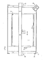
- Fig. 2 einen Koordinatenmeßtisch mit einem zweiachsig geführten Densitometer und einer zusätzlichen Bedienungseinrichtung,2 shows a coordinate measuring table with a two-axis densitometer and an additional operating device,
- Fig. 3 ein Schema der Meßfelderfassung,3 shows a diagram of the measurement field acquisition,
- Fig. 4 ein Schema für die Verstellung des Meßgerätes nach dem Abtasten der Referenzpunkte,4 shows a diagram for the adjustment of the measuring device after scanning the reference points,
- Fig. 5 ein Schema des Menüfeldes und den daraus resultierenden Funktionen.Fig. 5 is a diagram of the menu field and the resulting functions.
Fig. 1 zeigt ein Digitalisierungstableau 1, an dem mit einem Kontaktkabel 2.4 ein Griffel 2 angeschlossen ist. Auf dem Digitalisierungstableau 1 kann ein Druckbogen 3 mit Meßpunkten 2.1 - 2.3 und Farbmeßfeldern 14 - 14.2 willkürlich liegen. Je nach dem verbleibenden Platz zwischen den einzelnen Druckbildern des Druckfarbenauftrags sind die Farbmeßfelder 14 - 14.3 auf dem Druckbogen angeordnet.Fig. 1 shows a digitizing table 1, to which a
Die Farbmeßfelder 14 - 14.3 haben an ihrem Anfang und Ende Markierungen für den Griffel 2.The color measuring fields 14 - 14.3 have markings for the
Liegt der Druckbogen 3 auf dem Digitalisierungstableau 1 wahllos auf, dann werden zuerst mit dem Griffel 2 die Meßpunkte 2.1 - 2.3 abgetastet, um die Lage des Druckbogens 3 auf dem Digitalisierungstableau 1 zu fixieren. Danach wird der Griffel 2 auf ein Menüfeld 9 getastet um die-Lage der Farbmeßfelder 14 - 14.3 ohne großen Zeitaufwand für spätere Wiederholungsmessungen durch Tasten abzuspeichern. In der linken unteren Ecke des Digitalisierungstableaus 1 befindet sich ein Einmeßelement 17 zum Eichen der Berechnungskoordinaten zwischen Griffel 2 und dem Digitalisierungstableau 1 und einem Densitometer 8.If the printed
Fig. 2 zeigt das Digitalisierungstableau 1 auf einem Koordinatentisch 1.1. Das Densitometer 8 ist auf einer Traverse 15 verschiebbar, wobei die Traverse 15 mit Lagern 12, 13 auf einer Führungsschiene 11 verfahrbar ist. Damit kann das Densitometer 8 alle Flächenbereiche des Digitalisierungstableaus 1 anfahren. Die Traverse 15 ist mit Endanschlägen 16 beidseitig an der Führungsschiene 11 gesichert. Auf einer einer Bedienungskonsole 18 ist eine Tastatur 10 zum Eingeben der unterschiedlichsten Daten vorgesehen. Die Dateneingabe erfolgt besonders schnell durch Tasten mit dem Griffel 2 auf den gewünschten Punkt. Zwischen den Koordinatenmeßtisch 1.1 und dem Digitalisierungstableau 1 ist ein Übergangsbereich 19. In der linken unteren Ecke befindet sich ein Einmeßelement 17 für die Nulleichung.2 shows the digitizing table 1 on a coordinate table 1.1. The
In der Fig. 3 erkennt man die Dateneingabe der Meßpunkte 2.1 - 2.3 vom Griffel 2 zum Speicher 4. Die Koordinatenwerte der Farbmeßfelder 14 - 14.3 gelangen direkt zu einem Rechner 6. Vom Speicher 4 gelangen die Lagerwerte des Druckbogens 3 zum Rechner 6. Beide Datenwerte werden in einem Speicher 5 abgelegt, und können für die unterschiedlichsten Verwendungszwecke vom Speicher 5 abgerufen werden.3 shows the data input of the measuring points 2.1-2.3 from the
In der Fig. 4 ist erkennbar, daß lediglich zur Bogenerfassung die Meßpunkte 2.1 - 2.3 in den Speicher 4 eingegeben werden. Die Lagedaten der Farbmeßfelder 14 - 14.3 werden vom Speicher 5 direkt an den Rechner 6 weitergegeben, um vom Rechner 6 mit beiden Positionsdaten das Densitometer 8 ansteuern zu können. Die Lagedaten der Farbmeßfelder 14 - 14.3 sind innerhalb eines Druckauftrags immer an den gleichen Positionen. Mit dem Griffel 2 sind somit lediglich nur zwei Meßpunkte 2.1- 2.3 auf dem Digitalisierungstableau 1 zur Lageerkennung des Druckbogens 3 abzutasten.In FIG. 4 it can be seen that the measurement points 2.1-2.3 are entered into the
Wenn die Dehnung des Druckbogens zusätzlich mit erfaßt werden soll, werden drei Meßpunkte 2.1 - 2.3 mit dem Griffel 2 abgetastet.If the elongation of the printed sheet is also to be recorded, three measuring points 2.1-2.3 are scanned with the
Die Fig. 5 zeigt das Schema, wenn mit dem Griffel 2 ein Funktionsfeld des Menüfeldes 9 auf dem Digitalisierungstableau 1 abgetastet wird. Die vorgegebenen Daten des Menüfeldes 9 gelangen zu einem Rechner 7, der diese Werte mit Werten aus dem Speicher 4 zusammen verarbeitet. Vom Rechner 7 gelangen die aufbereiteten Daten zu den jeweiligen benötigten Funktionen.FIG. 5 shows the diagram when a functional field of the
- 1 Digitalisierungstableau1 digitization table
- 2 Griffel2 styles
- 2.1 Meßpunkte2.1 measuring points
- 2.2 "2.2 "
- 2.3 "2.3 "
- 3 Druckbogen3 printed sheets
- 4 Speicher4 memory
- 5 "5 "
- 6 Rechner6 computers
- 77
- 8 Densitometer8 densitometers
- 9 Menüfeld9 Menu field
- ' 10 Tastatur10 keyboard
- 11 Führungsschiene11 guide rail
- 12 Lager12 bearings
- 1313
- 14 - 14 -
- 14.3 Farbmeßfeld14.3 Color measuring field
- 15 Traverse15 traverse
- 16 Endanschlag16 end stop
- 17 Einmeßelement17 measuring element
- 18 Bedienungskonsole18 Control console
- 19 Übergangsfläche19 transition surface
- 1.1 Koordinatenmeßtisch1.1 coordinate measuring table
- 2.4 Kontaktkabel2.4 Contact cable
Claims (4)
dadurch gekennzeichnet,
daß die Lage der Druckbogen (3) und die Lage der Farbmeßfelder (14 - 14.3) des Druckbogens (3) mit einem an sich bekannten und handelsüblichen Digitalisierungstableau (1) und mit einem an diesem angeschlossenen Griffel (2) erfaßbar und in Speichern (4, 6) ablegbar sind.1.) Device for determining and evaluating color measurement fields on a printing sheet lying on a measuring table with a densitometer, in which the position of the color measurement fields and the printing sheet can be detected with a device and stored in memories, the densitometer, which can be moved in two directions, being stored Values can be moved repeatedly onto the color measuring fields of the printing sheet,
characterized,
that the position of the printed sheets (3) and the position of the color measuring fields (14 - 14.3) of the printed sheet (3) with a known and commercially available digitizing table (1) and with a stylus (2) connected to it can be recorded and stored (4 , 6) can be filed.
dadurch gekennzeichnet,
daß auf dem Digitalisierungstableau (1) ein Menüfeld (9) angeordnet ist, welches mittels des Griffels (2) zur Durchführung unterschiedlicher Funktionen abtastbar ist.2.) Device according to claim 1,
characterized,
that on the digitizing table (1) a menu field (9) is arranged, which can be scanned by means of the stylus (2) for performing different functions.
dadurch gekennzeichnet,
daß die Farbmeßfelder (14 - 14.3) an zwei Endpunkten mit dem Griffel (2) abtastbar sind.3.) Device according to claim 1,
characterized,
that the color measuring fields (14 - 14.3) can be scanned at two end points with the stylus (2).
dadurch gekennzeichnet,
daß der Druckbogen (3) an drei Meßpunkten (2.1 - 2.3) derart abtastbar ist, daß die Dehnung des Druckbogens (3) in zwei Richtungen kontrollierbar ist.4.) Device according to claim 1,
characterized,
that the printed sheet (3) can be scanned at three measuring points (2.1 - 2.3) in such a way that the elongation of the printed sheet (3) can be checked in two directions.
Applications Claiming Priority (2)
| Application Number | Priority Date | Filing Date | Title |
|---|---|---|---|
| DE19833324951 DE3324951A1 (en) | 1983-07-11 | 1983-07-11 | DEVICE FOR DETERMINING AND EVALUATING COLOR MEASURING FIELDS ON A PRINT SHEET LYING ON A MEASURING TABLE WITH A DENSITOMETER |
| DE3324951 | 1983-07-11 |
Publications (2)
| Publication Number | Publication Date |
|---|---|
| EP0131109A2 true EP0131109A2 (en) | 1985-01-16 |
| EP0131109A3 EP0131109A3 (en) | 1986-11-05 |
Family
ID=6203678
Family Applications (1)
| Application Number | Title | Priority Date | Filing Date |
|---|---|---|---|
| EP84105190A Ceased EP0131109A3 (en) | 1983-07-11 | 1984-05-08 | Device for determining and evaluating by a densitometer the colour swatches on a sheet placed on a measuring table |
Country Status (4)
| Country | Link |
|---|---|
| US (1) | US4660158A (en) |
| EP (1) | EP0131109A3 (en) |
| JP (1) | JPS6038638A (en) |
| DE (1) | DE3324951A1 (en) |
Cited By (1)
| Publication number | Priority date | Publication date | Assignee | Title |
|---|---|---|---|---|
| EP0277329A2 (en) * | 1987-02-03 | 1988-08-10 | Komori Corporation | A method of adjusting density measurement position |
Families Citing this family (9)
| Publication number | Priority date | Publication date | Assignee | Title |
|---|---|---|---|---|
| DE3738850A1 (en) * | 1987-11-16 | 1989-05-24 | Roland Man Druckmasch | METHOD FOR THE AUTOMATIC POSITION DETECTION OF PRINT CONTROL STRIPS FOR AUTOMATICALLY MEASURING COLOR DENSITY MEASUREMENT SYSTEMS |
| JPH01180436A (en) * | 1988-01-12 | 1989-07-18 | Fuji Photo Film Co Ltd | Scanner for pressure recording sheet |
| DE3924989A1 (en) * | 1989-07-28 | 1991-02-07 | Roland Man Druckmasch | DEVICE FOR CARRYING OUT A COMPREHENSIVE QUALITY CONTROL ON PRINT SHEETS |
| DE9002437U1 (en) * | 1990-03-02 | 1990-05-03 | Man Roland Druckmaschinen Ag, 6050 Offenbach, De | |
| US5208655A (en) * | 1991-08-07 | 1993-05-04 | Graphics Microsystems, Inc. | Method and apparatus for automatic densitometer alignment |
| DE4208709A1 (en) * | 1992-03-18 | 1993-09-23 | Combiring Engineering & Consul | Scanner for obtaining data from drawings - has scanner unit mounted on carriage that can be moved in X and Y directions to obtain data |
| DE4321179A1 (en) * | 1993-06-25 | 1995-01-05 | Heidelberger Druckmasch Ag | Method and device for controlling or regulating the operations of a printing machine |
| DE102007015097A1 (en) * | 2007-03-29 | 2008-10-02 | Heidelberger Druckmaschinen Ag | Colorimeter with coordinate adjustment |
| JP6494180B2 (en) * | 2014-05-28 | 2019-04-03 | 株式会社ミツトヨ | Position measuring device |
Citations (4)
| Publication number | Priority date | Publication date | Assignee | Title |
|---|---|---|---|---|
| DE3232490A1 (en) * | 1981-09-04 | 1983-03-31 | M.A.N.- Roland Druckmaschinen AG, 6050 Offenbach | Device for determining and evaluating ink measuring fields on a printed sheet |
| EP0087947A2 (en) * | 1982-02-27 | 1983-09-07 | Fanuc Ltd. | Method and apparatus for correcting shapes |
| EP0087945A1 (en) * | 1982-02-27 | 1983-09-07 | Fanuc Ltd. | Method and apparatus for setting coordinate system |
| EP0087944A1 (en) * | 1982-02-27 | 1983-09-07 | Fanuc Ltd. | Method and apparatus for entering graphics |
Family Cites Families (11)
| Publication number | Priority date | Publication date | Assignee | Title |
|---|---|---|---|---|
| DE2728738B2 (en) * | 1977-06-25 | 1979-05-10 | Roland Offsetmaschinenfabrik Faber & Schleicher Ag, 6050 Offenbach | Eulrichtung for checking and regulating the coloring on printing machines |
| DE3024773A1 (en) * | 1980-06-30 | 1982-01-28 | Grapho-Metronic Meß- und Regeltechnik GmbH & Co, KG, 8000 München | METHOD AND DEVICE FOR CONTROLLING AND CONTROLLING THE COLORING OF A MULTICOLOR PRINTING MACHINE |
| US4418390A (en) * | 1980-11-24 | 1983-11-29 | Smith Rhoda J | Method and apparatus for making a coded chart of a color subject |
| US4505589A (en) * | 1981-04-03 | 1985-03-19 | Gretag Aktiengesellschaft | Process and apparatus for the colorimetric analysis of printed material |
| JPS57165836A (en) * | 1981-04-06 | 1982-10-13 | Dainippon Screen Mfg Co Ltd | Method and apparatus for tracing and recording object to be traced |
| JPS5877606A (en) * | 1981-09-04 | 1983-05-11 | エム・ア−・エヌ−ロ−ラント・ドルツクマシ−ネン・アクチエンゲゼルシヤフト | Detector for position of printing paper on supporter |
| DE3136705C1 (en) * | 1981-09-16 | 1982-10-28 | M.A.N.- Roland Druckmaschinen AG, 6050 Offenbach | Process for the production of precise prints in printing machines |
| JPS58163001A (en) * | 1982-03-23 | 1983-09-27 | Toyoda Mach Works Ltd | Numerical controller equipped with interference checking function |
| JPS58201012A (en) * | 1982-05-19 | 1983-11-22 | Komori Printing Mach Co Ltd | Method for processing pattern signal |
| US4530061A (en) * | 1982-10-15 | 1985-07-16 | Wood-Tics Inc. | Method of producing stencils |
| US4558420A (en) * | 1982-10-25 | 1985-12-10 | Gerber Scientific Inc. | Computer generated mold for contoured garment piece formation |
-
1983
- 1983-07-11 DE DE19833324951 patent/DE3324951A1/en not_active Withdrawn
-
1984
- 1984-05-08 EP EP84105190A patent/EP0131109A3/en not_active Ceased
- 1984-07-05 JP JP59138081A patent/JPS6038638A/en active Pending
- 1984-07-11 US US06/629,638 patent/US4660158A/en not_active Expired - Lifetime
Patent Citations (4)
| Publication number | Priority date | Publication date | Assignee | Title |
|---|---|---|---|---|
| DE3232490A1 (en) * | 1981-09-04 | 1983-03-31 | M.A.N.- Roland Druckmaschinen AG, 6050 Offenbach | Device for determining and evaluating ink measuring fields on a printed sheet |
| EP0087947A2 (en) * | 1982-02-27 | 1983-09-07 | Fanuc Ltd. | Method and apparatus for correcting shapes |
| EP0087945A1 (en) * | 1982-02-27 | 1983-09-07 | Fanuc Ltd. | Method and apparatus for setting coordinate system |
| EP0087944A1 (en) * | 1982-02-27 | 1983-09-07 | Fanuc Ltd. | Method and apparatus for entering graphics |
Non-Patent Citations (1)
| Title |
|---|
| IBM TECHNICAL DISCLOSURE BULLETIN, Band 18, Nr. 5, Oktober 1975, Seiten 1589-1592, New York, US; P.L. GARDNER et al.: "Paper menus and keyboards for digitizing tablets" * |
Cited By (2)
| Publication number | Priority date | Publication date | Assignee | Title |
|---|---|---|---|---|
| EP0277329A2 (en) * | 1987-02-03 | 1988-08-10 | Komori Corporation | A method of adjusting density measurement position |
| EP0277329A3 (en) * | 1987-02-03 | 1990-07-18 | Komori Printing Machinery Co., Ltd. | A method of adjusting density measurement position |
Also Published As
| Publication number | Publication date |
|---|---|
| EP0131109A3 (en) | 1986-11-05 |
| US4660158A (en) | 1987-04-21 |
| JPS6038638A (en) | 1985-02-28 |
| DE3324951A1 (en) | 1985-01-24 |
Similar Documents
| Publication | Publication Date | Title |
|---|---|---|
| DE3719766C2 (en) | ||
| EP0114914B1 (en) | Device for detecting and evaluating colour control strips on a printing sheet | |
| EP0064024B1 (en) | Method and device for the colorimetric analysis of a printed colour test scale | |
| DE2922965C2 (en) | ||
| DE19716066C1 (en) | Manual measurement device for reflection measurement on printed sheets and test patterns | |
| DE2731842B2 (en) | Method for determining changes in the halftone value of a color of printed sheets or webs caused by shifting and / or doubling | |
| DE19858130A1 (en) | Measuring rule for electronic position measuring device | |
| EP0266713A1 (en) | Device for measuring distances on a workpiece and slide gauge provided with digital indication of the measured distances | |
| EP0131109A2 (en) | Device for determining and evaluating by a densitometer the colour swatches on a sheet placed on a measuring table | |
| DE3232490C2 (en) | ||
| DE3527652A1 (en) | FASTENING MECHANISM FOR A MEASURING SYSTEM WITH MAGNETIC SCALE | |
| DE2229500B2 (en) | Method and device for specifying the setting of the ink zone screws of a printing press | |
| DE2919419C2 (en) | Process for marking, evaluating or measuring screens and the device for carrying out this process | |
| EP0968637A2 (en) | Method and device for gauging a device for producing electrical components | |
| DE2735943C2 (en) | Device for checking the print quality of multi-colored printed sheets stored in a stack | |
| DE3701775C2 (en) | Thickness monitor | |
| EP0299445B1 (en) | Manual instrument for reflection measurements | |
| DE3915587C1 (en) | Measurement element for multiple colour offset printing - determines match difference between two partial images independently of quality of image signal | |
| DE2713004A1 (en) | POSITION TRANSDUCERS FOR MACHINE TOOLS AND MEASURING DEVICES OR MACHINERY | |
| EP0450129A1 (en) | Keyboard with definable keys | |
| DE4301272A1 (en) | Device for determining the register error between the individual colors in multi-color printing in a long web web-fed rotary printing press | |
| DE3631204A1 (en) | DEVICE ON PRINTING MACHINES FOR DENSITOMETRICALLY DETECTING A MEASURING FIELD STRIP | |
| DE19840301A1 (en) | Printing graphical illustrations on both sides of base material with digital triggering of two individual printing units on smooth printing material like paper or plastics film | |
| DE3503116A1 (en) | MEASURING INSTRUMENT | |
| DE102007009883A1 (en) | Color measuring strip identification method for offset printing machine, involves assigning color measuring values to inks so that ink sequence is compared with color measuring strip type, which has largest probability that is selected |
Legal Events
| Date | Code | Title | Description |
|---|---|---|---|
| PUAI | Public reference made under article 153(3) epc to a published international application that has entered the european phase |
Free format text: ORIGINAL CODE: 0009012 |
|
| AK | Designated contracting states |
Designated state(s): AT CH FR GB IT LI NL SE |
|
| PUAL | Search report despatched |
Free format text: ORIGINAL CODE: 0009013 |
|
| AK | Designated contracting states |
Kind code of ref document: A3 Designated state(s): AT CH FR GB IT LI NL SE |
|
| 17P | Request for examination filed |
Effective date: 19861009 |
|
| 17Q | First examination report despatched |
Effective date: 19880108 |
|
| STAA | Information on the status of an ep patent application or granted ep patent |
Free format text: STATUS: THE APPLICATION HAS BEEN REFUSED |
|
| 18R | Application refused |
Effective date: 19881224 |
|
| RIN1 | Information on inventor provided before grant (corrected) |
Inventor name: ZINGHER, ODED |