EP0130880B1 - Moteur à combustion interne du type à pistons en ligne - Google Patents
Moteur à combustion interne du type à pistons en ligne Download PDFInfo
- Publication number
- EP0130880B1 EP0130880B1 EP19840401260 EP84401260A EP0130880B1 EP 0130880 B1 EP0130880 B1 EP 0130880B1 EP 19840401260 EP19840401260 EP 19840401260 EP 84401260 A EP84401260 A EP 84401260A EP 0130880 B1 EP0130880 B1 EP 0130880B1
- Authority
- EP
- European Patent Office
- Prior art keywords
- cylinder head
- cylinder
- combustion engine
- crankshaft
- bearings
- Prior art date
- Legal status (The legal status is an assumption and is not a legal conclusion. Google has not performed a legal analysis and makes no representation as to the accuracy of the status listed.)
- Expired
Links
- 238000002485 combustion reaction Methods 0.000 title claims description 11
- 230000008878 coupling Effects 0.000 claims description 6
- 238000010168 coupling process Methods 0.000 claims description 6
- 238000005859 coupling reaction Methods 0.000 claims description 6
- 238000007667 floating Methods 0.000 claims description 6
- 230000007423 decrease Effects 0.000 claims description 3
- 241001125877 Gobio gobio Species 0.000 claims 1
- 239000003921 oil Substances 0.000 description 8
- 230000008901 benefit Effects 0.000 description 5
- 229910052782 aluminium Inorganic materials 0.000 description 4
- XAGFODPZIPBFFR-UHFFFAOYSA-N aluminium Chemical compound [Al] XAGFODPZIPBFFR-UHFFFAOYSA-N 0.000 description 4
- XLYOFNOQVPJJNP-UHFFFAOYSA-N water Substances O XLYOFNOQVPJJNP-UHFFFAOYSA-N 0.000 description 4
- 238000001816 cooling Methods 0.000 description 3
- 239000007789 gas Substances 0.000 description 3
- 230000011218 segmentation Effects 0.000 description 3
- 241000271897 Viperidae Species 0.000 description 2
- 238000009826 distribution Methods 0.000 description 2
- 238000005516 engineering process Methods 0.000 description 2
- 238000001125 extrusion Methods 0.000 description 2
- 238000009776 industrial production Methods 0.000 description 2
- 239000010687 lubricating oil Substances 0.000 description 2
- 238000003754 machining Methods 0.000 description 2
- 238000007789 sealing Methods 0.000 description 2
- 235000008612 Gnetum gnemon Nutrition 0.000 description 1
- 240000000018 Gnetum gnemon Species 0.000 description 1
- 229910000831 Steel Inorganic materials 0.000 description 1
- 238000004026 adhesive bonding Methods 0.000 description 1
- 239000004411 aluminium Substances 0.000 description 1
- 235000020303 café frappé Nutrition 0.000 description 1
- 239000000470 constituent Substances 0.000 description 1
- 239000002826 coolant Substances 0.000 description 1
- 230000018109 developmental process Effects 0.000 description 1
- 238000009413 insulation Methods 0.000 description 1
- 238000005461 lubrication Methods 0.000 description 1
- 238000004519 manufacturing process Methods 0.000 description 1
- 229910052751 metal Inorganic materials 0.000 description 1
- 239000002184 metal Substances 0.000 description 1
- 239000000203 mixture Substances 0.000 description 1
- 239000011819 refractory material Substances 0.000 description 1
- 238000003303 reheating Methods 0.000 description 1
- 238000004513 sizing Methods 0.000 description 1
- 239000010959 steel Substances 0.000 description 1
- 230000004584 weight gain Effects 0.000 description 1
- 235000019786 weight gain Nutrition 0.000 description 1
Images


Classifications
-
- F—MECHANICAL ENGINEERING; LIGHTING; HEATING; WEAPONS; BLASTING
- F02—COMBUSTION ENGINES; HOT-GAS OR COMBUSTION-PRODUCT ENGINE PLANTS
- F02B—INTERNAL-COMBUSTION PISTON ENGINES; COMBUSTION ENGINES IN GENERAL
- F02B75/00—Other engines
- F02B75/16—Engines characterised by number of cylinders, e.g. single-cylinder engines
- F02B75/18—Multi-cylinder engines
- F02B75/20—Multi-cylinder engines with cylinders all in one line
-
- F—MECHANICAL ENGINEERING; LIGHTING; HEATING; WEAPONS; BLASTING
- F02—COMBUSTION ENGINES; HOT-GAS OR COMBUSTION-PRODUCT ENGINE PLANTS
- F02F—CYLINDERS, PISTONS OR CASINGS, FOR COMBUSTION ENGINES; ARRANGEMENTS OF SEALINGS IN COMBUSTION ENGINES
- F02F7/00—Casings, e.g. crankcases
- F02F7/0043—Arrangements of mechanical drive elements
- F02F7/0046—Shape of casings adapted to facilitate fitting or dismantling of engine parts
-
- F—MECHANICAL ENGINEERING; LIGHTING; HEATING; WEAPONS; BLASTING
- F02—COMBUSTION ENGINES; HOT-GAS OR COMBUSTION-PRODUCT ENGINE PLANTS
- F02F—CYLINDERS, PISTONS OR CASINGS, FOR COMBUSTION ENGINES; ARRANGEMENTS OF SEALINGS IN COMBUSTION ENGINES
- F02F7/00—Casings, e.g. crankcases
- F02F7/0065—Shape of casings for other machine parts and purposes, e.g. utilisation purposes, safety
- F02F7/008—Sound insulation
-
- F—MECHANICAL ENGINEERING; LIGHTING; HEATING; WEAPONS; BLASTING
- F02—COMBUSTION ENGINES; HOT-GAS OR COMBUSTION-PRODUCT ENGINE PLANTS
- F02B—INTERNAL-COMBUSTION PISTON ENGINES; COMBUSTION ENGINES IN GENERAL
- F02B75/00—Other engines
- F02B75/16—Engines characterised by number of cylinders, e.g. single-cylinder engines
- F02B75/18—Multi-cylinder engines
- F02B2075/1804—Number of cylinders
- F02B2075/1816—Number of cylinders four
-
- F—MECHANICAL ENGINEERING; LIGHTING; HEATING; WEAPONS; BLASTING
- F02—COMBUSTION ENGINES; HOT-GAS OR COMBUSTION-PRODUCT ENGINE PLANTS
- F02B—INTERNAL-COMBUSTION PISTON ENGINES; COMBUSTION ENGINES IN GENERAL
- F02B2275/00—Other engines, components or details, not provided for in other groups of this subclass
- F02B2275/20—SOHC [Single overhead camshaft]
Definitions
- the present invention relates to an internal combustion engine and applies more particularly to inline piston scorers.
- An essential aim of the invention is to present a new structure of an internal combustion engine whose technology aims:
- the energy dissipated by friction is mainly located in the shaft line, the crankpins as well as at the level of the pistors and the camshaft.
- the invention then proposes to lighten the piston as much as possible; the greatest weight gain will be obtained by the use of a connecting rod end known as a "viper head" which makes it possible to reduce the length and the diameter of the piston pin.
- the invention finally proposes to reduce the diameters of the camshaft bearings as much as possible.
- crankshaft comprising its connecting rods and pistons cannot be mounted in a cylinder block whose spacing of the cylinders does not allow the passage of the pistons with respect to the bearings of crankshaft.
- This reduced center distance of the cylinders is justified by the lightness and size of the engine necessary for the increase in its specific power.
- the invention proposes to insert shirts added into the cylinder head extended for this purpose on the length of the embedding.
- an internal combustion engine according to the invention of the in-line piston type and comprising a cylinder head, a cylinder block consisting of two half-casings, the assembly plane of which coincides with the plane containing the cylinder axes and forming after assembly, crankshaft bearings and an oil bowl, and a movable coupling comprising in particular a monobloc connecting rod and a crankshaft with removable elements this cylinder head being extended over a height necessary for the fitting of at least one attached and suspended jacket, is characterized in that these crankpins and journals are mounted in floating rings so as to reduce the average friction pressure by reducing the diameters thereof.
- this monobloc connecting rod has a connecting rod whose thickness gradually decreases towards a piston articulated on the latter, so as to lighten this piston by reducing the length of the diameter of its piston pin.
- these two cylinder halves naturally form after assembly, crankshaft bearings and an oil bowl, so as to increase the rigidity of the engine and lower its noise level.
- the cylinder head is extended over a height necessary for the fitting of at least one attached and suspended shirt.
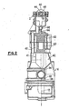
- FIGS. 1 and 2 show an in-line multi-cylinder internal combustion engine, in accordance with the invention, which in particular comprises a cylinder head 2, a cylinder block 4 and a movable coupling 6.
- This movable coupling comprises a crankshaft 8, connecting rods 10 and pistons 12.
- Each connecting rod 10 of the monobloc type called “eye” has a connecting rod foot 14 called “viper head” whose thickness gradually decreases towards the corresponding piston 12 articulated on the latter via d 'A piston pin 16.
- the crankshaft 8 is conatitué by crank pins 81 and pins 82, connected by arms 83 and mounted in floating rings 84 coated with anti-friction.
- Each piston 12 moves in a suspended jacket 18 embedded in the cylinder head 2 and free from deformation.
- Each piston skirt 20 has the necessary and sufficient lift.
- the piston pins 16 are mounted tight in the connecting rod feet 14 and, as a result, the pistons 12 will be assembled on the connecting rods 10 before mounting of the latter on the crankshaft 8.
- This mobile coupling 6 therefore has very low rotation masses which can be fully balanced cylinder by cylinder. Thanks to its lightening possibilities and the reduced dimensioning of its crank pins 81 and journals 82, the crankshaft 8 nevertheless retains a high natural frequency.
- the cylinder block 4 is formed by two half-casings 41 and 42, the assembly plane of which coincides with the plane 21 containing the cylinder axes 22.
- the cylinder head 2 fitted with recessed and suspended liners 18 is lowered, for the assembly of the engine, on the pistons 12 held in the same plane by a suitable assembly.
- the possibility of strapping segmentation 24 remains whole and practical.
- the cylinder head 2 is positioned in its final place, with the clearance necessary for styling the crankshaft 8 and the liners 18 by the half-casings-cylinders 41 and 42. All that remains is to secure these with the cylinder head 2 by screwing when assembled.
- the advantages which result from the technology specific to the engine structure described above are numerous.
- the hanging folders 18 are free from deformation; their embedding in the cylinder head 2, produced by fitting and gluing, dispenses with the use of a cylinder head gasket. They will be finished machining before fitting.
- the cylinder head 2 will be assembled with the half-casings-cylinders 41, 42 by screws 26 whose location and sizing are no longer dictated by the concern for sealing a cylinder head gasket. A different distribution thereof is therefore possible and results in the possibility of placing two spark plugs 28 per cylinder under the best conditions.
- the half-casings-cylinders 41, 42 are very easily obtained from die-cast aluminum, in a mold where they can be arranged in pairs; they make it possible to mold internal shapes such as pockets, so as to increase the volume of lubricating oil for a given size.
- the assembled half-cylinder-casings 41, 42 naturally form the crankshaft bearings 30 and the oil bowl 32. Once capped by the cylinder head 2, they form a closed box which has great rigidity and great lightness.
- the fixing screws 34 at the right of each crankshaft bearing no longer support the maximum forces and can be minimized in the same way as the fixing screws 26 of the cylinder head 2.
- the assembled 41.42 cylinder half-casings therefore replace a traditional cylinder block fitted with its caps and its oil bowl. They ensure a good 360 ° connection with a gearbox housing to avoid its flapping.
- the shaft line is particularly stiffened, which contributes to obtaining good straightness and reducing the noise level and friction. The latter are moreover reduced by the use of floating bearing rings 84.
- a chamber 36 naturally forms around the sleeves 18 in the assembled half-casings 41 and 42; it will be used for the passage of the lubricating oil from the engine before its distribution to the various points to be lubricated.
- This chamber is sealed at its upper part by the cylinder head gasket plane 41, 42.
- an O-ring 38 located on the side of the connecting rod chamber ensures the sealing, and constitutes an anti-vibration support point for shirts.
- This oil chamber is surrounded by a water chamber 40 which regulates by thermal transfer, the temperature of the oil whose viscosity will be as low as possible.
- the sleeves 18 transfer calories to the oil which rises rapidly in temperature, thus contributing to the reduction of friction losses in the so-called "cold" use phases.
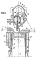
- the cylinder head 2 detailed in FIGS. 3 and 4 is of the crossflow type, with an intake heated by the exhaust gases. It comprises a single overhead camshaft 44 carried by a cover 46 which forms the upper half-bearings 48 thereof. Lower half-bearings 50 are attached to the joint plane of the cover 44. They are housed inside this cylinder head 2 and allow a plane joint to be obtained.
- valves 52 perpendicular to the plane of the cylinder head-casing joint, are arranged for each cylinder, on either side of the longitudinal engine plane 21 containing the cylinder axes 22. These valves are attacked by latches 54 which are based on hydraulic ball joints 56.
- This cylinder head has no combustion chamber, the latter 58 being of the heron type in the piston 12.
- This cylinder head is equipped with two spark plugs 28 per cylinder for the use of a lean mixture with partial loads, and recessed shirts 18.
- the cylinder head 2 with its cover 46 and its half-bearings 48 and 50 is die-cast under pressure.
- the use of sand cores to obtain the water chamber 40 is thus avoided.
- This annular water chamber surrounds the liners 18 over their entire height and the thickness of the chamber bottom 60 of the cylinder head.
- cooling conduits 62 pierced or coming from the foundry, housed in this flat chamber bottom 60.
- These conduits 62 are disposed between the. valves 52 and spark plugs 28, and in the inter-cylinder planes. They flow to all the inter-seats 64 of valves in conduits 66 which are perpendicular to them and which open into a longitudinal manifold 68.
- the coolant is forced to travel through the hottest zones of the cylinder head 2, at high speed and for the benefit of heat exchanges.
- valve guides 70 intersect at manifold 68 and benefit from direct cooling.
- a water outlet is traditionally fitted at the end of this collector. It follows that the valves 52, spark plugs 28, fixing screw 26 of the cylinder head 2, exhaust gas supply ducts 71 on the intake manifold face - for reheating the latter -, are particularly arranged. depending on cooling requirements.
- All parts of the cylinder head 2 can be obtained in a metal mold; only the intake ducts 72 are outlined by suitable daggers, and terminated in machining so as not to harm their aerodynamics.
- the exhaust ducts 74 are cased with a refractory material to conserve the heat of the gases (post-combustion, turbo-compressor, insulation of the cylinder head).
Landscapes
- Engineering & Computer Science (AREA)
- Chemical & Material Sciences (AREA)
- Combustion & Propulsion (AREA)
- Mechanical Engineering (AREA)
- General Engineering & Computer Science (AREA)
- Cylinder Crankcases Of Internal Combustion Engines (AREA)
- Shafts, Cranks, Connecting Bars, And Related Bearings (AREA)
Description
- La présente invention se rapporte à un moteur à combustion interne et s'appligue plus particulièrement aux noteurs a pistons en ligne.
- Un but essentiel de l'invention est de présenter une nouvelle structure de moteur à combustion interne dont la technologie vise:
-
- - à diminuer la pression moyenne de frottement, d'une part;
- - et à augmenter la rigidité du moteur et abaisser son niveau sonore tout en accroissant sa puissance massique et en diminuant son prix de revient et sa consonnation, d'autre part.
- Dans le cadre du premier objectif visé, il est connu que l'énergie dissipée par les frottements se situe principalement dans la ligne d'arbre, les manetons ainsi qu'au niveau des pistors et de l'arbre à cames.
- Pour atteindre ce premier objectif, l'invention propose d'abord de réduire au maximum les diamètres des tourillons et des manetons en employant des organes connus suivants:
- - une bielle en aluminium forgé dont la fiabilité et le poids tendent vers un optimum lorsque celle-ci est dite "à oeil"; cette bielle se distingue par un prix de revient faible et son montage exige un vilebrequin démontable.
- - Un vilebrequin en plusieurs éléments dont les manetons, les bras et les tourillons s'obtiennent facilemept par frappe et extrusion; l'assenblage . de ces"d1fférents éléments s'effectue traditionnellement à la presse à l'aide de moyens mécanisés; un acier approprié donnera à ce vilebrequin, une résistance mécanique élevée et également une grande dureté superficielle des tourillons et des manetons.
- - Des bagues flottantes revêtues d'anti-friction, à la place des demi-coussinets traditionnels; celles-ci présentent un prix de revient plus faible, supportent des pressions maximales plus élevées et induisent une diminution de frottement.
- Les bielles, le vilebrequin et les bagues flottantes précités nécessitent de faibles investissements pour leur production en grande série. Cet attelage mobile ainsi constitué permet donc de réduire les diamètres des tourillons et des manetons au maximum.
- Pour atteindre ce premier objectif, l'invention propose ensuite d'alléger au maximum le piston; le gain de poids le plus important sera obtenu par l'emploi d'un pied de bielle dit en "tête de vipère" qui permet de réduire la longueur et le diamètre de l'axe de piston.
- Pour atteindre ce premier objectif, l'invention propose enfin de réduire au maximum les diamètres des paliers d'arbre à cames.
- Dans le cadre du deuxième objectif visé, il est connu qu'un vilebrequin comportant ses bielles et pistons ne peut être monté dans un carter-cylindres dont l'entraxe des cylindres ne permet pas le passage des pistons vis-à-vis des paliers de vilebrequin. Cet entraxe réduit des cylindres est justifié par la légèreté et l'encombrement du moteur nécessaires à l'accroissement de sa puissance massique.
- C'est pourquoi l'invention propose comme le suggère le document GB-A-1.565.779 (WOOD) en premier lieu et en tenant compte des fonctions induites par la réalisation du premier objectif visé, de couper le carter-cylindres en deux parties, particulièrement pour permettre le montage de l'attelage mobile préalablement assemblé, dans un moteur en ligne, suivant un plan d'assemblage qui coincide avec le plan contenant les axes des cylindres. Ces deux demi-carters seront notamment en aluminium coulé sous pression.
- En second lieu, l'invention propose d'enscatrer des chemises rapportées dans la culasse prolongée à cet effet sur la bauteur de l'encastrement.
- Par conséquent, suivant une particularité de l'invention, un moteur à combustion interne conforme à l'invention, du type à piston en ligne et comprenant une culasse, un carter-cylindre constitué de deux, demi-carters dont le plan d'assemblage coincide avec le plan contenant les axes de cylindre et formant après assemblage, des paliers de vilebrequin et une cuvette à huile, et un attelage mobile comprenant notamment une bielle monobloc et un vilebrequin à éléments démontables cette culasse étant prolongée sur une hauteur nécessaire à l'encastrement d'au moins une chemise rapportée et suspendue, est caractérisé en ce que ces manetons et tourillons sont montés dans des bagues flottantes de manière à diminuer la pression moyenne de frottement par réduction des diamètres de ceux-ci.
- Suivant une autre particularité de l'invention, cette bielle monobloc présente un pied de bielle dont l'épaisseur diminue progressivement en direction d'un piston articulé sur ce dernier, de manière à alléger ce piston par réduction de la longueur de la diamètre de son axe de piston.
- Suivant une autre particularité de l'invention, ces deux demi-carterscylindres forment naturellement après assemblage, des paliers de vilebrequin et une cuvette à huile, de manière à accroître la rigidité du moteur et à abaisser son niveau sonore.
- Suivant une autre particularité de l'invention, la culasse est prolongée sur une hauteur nécessaire à l'encastrement d'au moins une chemise rapportée et suspendue.
- D'autres particularités et avantages de l'invention ressortiront de la destription qui va suivre d'un mode de réalisation donné à titre d'exemple non limitatif et illustré par des dessins annexes dans lesquels:
- - la figure 1 est une vue partielle en coupe longitudinale suivant un plan passant par l'axe du vilebrequin et les axes des cylindres, d'un moteur conforme à l'invention;
- - la figure 2 est une vue de droite du moteur représenté à la figure 1 et coupé dans le plan d'un palier;
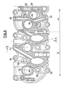
- - la figure 3 est une vue de dessus du moteur représenté à la figure 1, montrant la culasse de celui-ci suivant la ligne de coupe a, des figures 1 et 4;
- - la figure 4 est une vue partielle du moteur représenté à la figure 3, en coupe transversale suivant la ligne y 8, et;
- - la figure 5 est une vue schématique en éclaté d'un moteur conforme à l'invention.
- Les figures 1 et 2 montrent un moteur à combustion interne multicylindres en ligne, conforme à l'invention, qui comprend notamment une culasse 2, un carter-cylindres 4 et un attelage mobile 6. Cet attelage mobile comporte un vilebrequin 8, des bielles 10 et des pistons 12. Chaque bielle 10 du type monobloc dit "à oeil" présente un pied de bielle 14 dit "en tête de vipère" dont l'épaisseur diminue progressivement en direction du piston correspondant 12 articulé sur ce dernier par l'intermédiaire d'un axe de piston 16. Le vilebrequin 8 est conatitué par des manetons 81 et des tourillons 82, reliés par des bras 83 et montés dans des bagues flottantes 84 revêtues d'anti-friction.
- Chaque piston 12 se déplace dans une chemise suspendue 18 encastrée dans la culasse 2 et exempte de déformation. Chaque jupe de piston 20 présente la portance nécessaire et suffisante. Les axe de piston 16 sont montés serrés dans les pieds de bielle 14 et de ce fait, les pistons 12 seront assemblés sur les bielles 10 avant le montage de cellea-ci sur le vilebrequin 8.
- Cet attelage mobile 6 presente donc des masses rotation elles très faibles qui peuvent être totalement équilibrées cylindre par cylindre. Grâce à ses possibilités d'allégement et au dimensionnement réduit de ses manetons 81 et tourillons 82, le vilebrequin 8 conserve quand même une fréquence propre élevée.
- Le carter-cylindres 4 est formé de deux demi-carters 41 et 42 dont le plan d'assemblage coïncide avec le plan 21 contenant les axes de cylindre 22.
- La culasse 2 équipée des chemises encastrées et suspendues 18 est descendue, pour l'assemblage du moteur, sur les pistons 12 maintenus dans un même plan par un montage adapté. La possibilité de sangler la segmentation 24 reste entière et pratique. La culasse 2 est positionnée à sa place définitive, au jeu près nécessaire au coiffage du vilebrequin 8 et des chemises 18 par les demi-carters-cylindres 41 et 42. Il ne reste plus gu'à solidariser ceux-ci avec la culasse 2 par vissage lorsqu'ils sont assemblés.
- Les avantages qui résultent de la technologie propre à la structure de moteur précédemment décrite sont multiples. Les chemises suspendues 18 sont exemptes de déformations; leur encastrement dans la culasse 2, réalisé par emmanchement et collage, dispense d'employer un joint de culasse. Elles seront terminées d'usinage avant emmanchement.
- La culasse 2 sera assemblée avec les demi-carters-cylindres 41,42 par des vis 26 dont l'emplacement et le dimensionnement ne sont plus dictés par le souci d'étanchéité d'un joint de culasse. Une répartition différente de celle-ci s'avère donc possible et entraîne la.possibilité de placer deux bougies 28 par cylindre dans les meilleures conditions.
- Les demi-carters-cylindres 41, 42 s'obtiennent très facilement en aluminium coulé sous pression, dans un moule où ils peuvent être disposés par paire; ils permettent de mouler des formes intérieures telles que des poches, de manière à accroître le volume d'huile de lubrification pour un encombrement donné.
- Les demi-carters-cylindres 41, 42 assemblés forment naturellement les paliers de vilebreguin 30 et la cuvette à huile 32. Une fois coiffés par la culasse 2, ils forment une boîte fermée qui présente une grande rigidité et une grande légèreté.
- Les vis de fixation 34 au droit de chaque palier de vilebrequin ne supportent plus les efforts maximaux et peuvent être minimisées au même titre que les vis de fixation 26 de la culasse 2.
- Les demi-carters-cylindres 41,42 assemblés remplacent donc un carter-cylindres traditionnel muni de ses chapeaux et de sa cuvette à huile. Ils permettent d'assurer une bonne liaison sur 360° avec un carter de boîte de vitesses pour éviter ainsi son battement. La ligne d'arbre est particulièrement rigidifiée, ce qui concourt à l'obtention d'une bonne rectitude et à la diminution du niveau sonore et des frottements. Ces derniers sont d'ailleurs réduits par l'emploi des bagues de palier flottantes 84.
- Une chambre 36 se forme naturellement autour des chemises 18 dans les demi-carters 41 et 42 assemblés; elle servira au passage de l'huile de graissage du moteur avant sa distribution aux différents points à graisser.
- L'étanchéité de cette chambre est réalisée, à sa partie supérieure, par le plan de joint culasse 2- carters 41, 42. A la partie inférieure, un joint torique 38 situé du côté de la chambre de bielles assure l'étanchéité, et constitue un point d'appui anti-vibratoire des chemises.
- Cette chambre d'huile est entourée par une chambre d'eau 40 qui régule par transfert thermigue, la températuie de l'huile dont la viscosité sera la plus réduite possible. Les chemises 18 cèdent des calories à l'huile qui monte rapidement en température, contribuant ainsi à la diminution des pertes par frottement dans les phases d'utilisation dites "froides".
- La culasse 2 détaillée sur les figures 3 et 4 est du type crossflow, avec une admission réchauffée par les gaz d'échappement. Elle comporte un seul arbre à cames en tête 44 porté par un couvercle 46 gui forme les demi-paliers supérieurs 48 de celui-ci. Des demi-paliers inférieurs 50 sont rapportés sur le plan de joint du couvercle 44. Ils se logent à l'intérieur de cette culasse 2 et permettent l'obtention d'un joint de couvercle plan.
- Le dimensionuement de ces demi-paliers supérieurs 48 et inférieurs 50 est approprié à la tenue mécanigue de l'arbre à cames 44 en étant le plus réduit possible pour diminuer les frottements au maximum.
- Dans cette culasse 2, des soupapes 52 perpendiculaires au plan de joint culasse-carters, sont disposées pour chaque cylindre, de part et d'autre du plan longitudinal moteur 21 contenant les axes de cylindre 22. Ces soupapes sont attaquées par des linguets 54 qui s'appuient sur des rotules hydrauliques 56. Cette culasse est dépourvue de chambre de combustion, cette dernière 58 étant du type héron dans le piston 12. Cette culasse est équipée des deux bougies 28 par cylindre pour l'utilisation d'un mélange pauvre aux charges partielles, et des chemises encastrées 18.
- Pour une réalisation industrielle particulièrement économique, la culasse 2 avec son couvercle 46 et ses demi-paliers 48 et 50 est coulée sous pression. L'emploi de noyaux sable pour obtenir la chambre d'eau 40 est ainsi évité. Cette chambre d'eau annulaire entoure les chemises 18 sur toute leur hauteur et l'épaisseur du fond de chambre 60 de la culasse.
- Elle alimente à sa partie supérieure des conduits de refroidissement 62 percés ou venant de fonderie, logés dans ce fond de chambre plat 60. Ces conduits 62 sont disposés entre les . soupapes 52 et les bougies 28, et dans les plans inter-cylindres. Ils débitent à tous les inter-sièges 64 de soupapes dans des conduits 66 qui leur sont perpendiculaires et qui débouchent dans un collecteur longitudinal 68. Ainsi, le fluide refroidisseur est astreint à parcourir les zones les plus chaudes de la culasse 2, à grande vitesse et au bénéfice des échanges thermiques.
- Tous les guides de soupape 70 sont sécants au collecteur 68 et bénéficient d'un refroidissement direct. Une sortie d'eau est aménagée traditionnellement en extrémité de ce collecteur. Il s'ensuit que les soupapes 52, bougies 28, vis de fixation 26 de la culasse 2, conduits d'amenée des gaz d'échappement 71 sur la face collecteur d'admission - pour le réchauffage de ce dernier -, sont particulièrement disposés en fonction des impératifs de refroidissement.
- Toutes les parties de la culasse 2 peuvent être obtenues en moule métallique; seuls les conduits d'admission 72 sont ébauchés par des poignards appropriés, et terminés en usinage afin de ne pas nuire à leur aérodynamisme. Les conduits d'échappement 74 sont tubés avec un matériau réfractaire pour conserver la chaleur des gaz (post-combustion, turbo-compresseur, isolation de la culasse).
- Toutes les pièces constitutives d'un moteur à combustion interne réalisé conformément à la présente invention présentent par ailleurs l'avantage inhérent de faciliter l'élaboration des circuits de graissage et de retour d'huile car elles ne forment en général aucun corps creux fermé. De ce fait, leur réalisation industrielle est facilitée.
- Comme on peut le constater sur la figure 5, ces pièces peuvent être aisément assemblées de façon entièrement automatique de la manière suivante:
- - on assemble les pistons 12 sur les bielles 10;
- - on monte ces bielles sur le vilebreguin 8;
- - on encastre les chemises suspendues 18 dans la culasse 2;
- - on descend cette culasse 2 suivant la flèche F1, équipée des chemises suspendues 18 sur les pistons 12 à segmentation préalablement sanglée, maintenus dans un même plan par un montage adapté, jusqu'à une position déterminée;
- - on coiffe le vilebrequin 8 et les chemises suspendues 18 par les demi-carters-cylindres 41, 42 suivant les fléches F2;
- - on assemble ces demi-carters-cylindres par vissage;
- - et on assemble la culasse 2 sur ces demi-carters-cylindres par vissage.
Claims (4)
Applications Claiming Priority (2)
| Application Number | Priority Date | Filing Date | Title |
|---|---|---|---|
| FR8310296 | 1983-06-22 | ||
| FR8310296A FR2547865B1 (fr) | 1983-06-22 | 1983-06-22 | Structure et procede d'assemblage pour un moteur a combustion interne du type a pistons en ligne |
Publications (2)
| Publication Number | Publication Date |
|---|---|
| EP0130880A1 EP0130880A1 (fr) | 1985-01-09 |
| EP0130880B1 true EP0130880B1 (fr) | 1987-01-14 |
Family
ID=9290042
Family Applications (1)
| Application Number | Title | Priority Date | Filing Date |
|---|---|---|---|
| EP19840401260 Expired EP0130880B1 (fr) | 1983-06-22 | 1984-06-19 | Moteur à combustion interne du type à pistons en ligne |
Country Status (4)
| Country | Link |
|---|---|
| EP (1) | EP0130880B1 (fr) |
| DE (1) | DE3462060D1 (fr) |
| ES (1) | ES8600460A1 (fr) |
| FR (1) | FR2547865B1 (fr) |
Family Cites Families (7)
| Publication number | Priority date | Publication date | Assignee | Title |
|---|---|---|---|---|
| FR809758A (fr) * | 1935-09-02 | 1937-03-10 | Hirth Motoren G M B H | Carter pour moteurs, particulièrement pour moteurs légers, tels que moteurs d'automobiles et d'avions |
| FR1511082A (fr) * | 1966-12-15 | 1968-01-26 | Peugeot | Nouvel agencement de l'arbre à cames sur un moteur thermique ou compresseur et machine en résultant |
| US3479929A (en) * | 1968-02-19 | 1969-11-25 | Caterpillar Tractor Co | Piston pin |
| US3521613A (en) * | 1968-09-17 | 1970-07-28 | Aldo Celli | Engine with die-cast static parts |
| US3851631A (en) * | 1973-03-16 | 1974-12-03 | Kiekhaefer Aeromarine Motors | Die cast v-type two-cycle engine |
| GB1565799A (en) * | 1976-11-01 | 1980-04-23 | Wood J | Internal combustion engine body construction |
| FR2420696A1 (fr) * | 1978-03-21 | 1979-10-19 | Citroen Sa | Perfectionnements aux embiellages de moteur a combustion interne |
-
1983
- 1983-06-22 FR FR8310296A patent/FR2547865B1/fr not_active Expired
-
1984
- 1984-06-19 EP EP19840401260 patent/EP0130880B1/fr not_active Expired
- 1984-06-19 DE DE8484401260T patent/DE3462060D1/de not_active Expired
- 1984-06-20 ES ES533581A patent/ES8600460A1/es not_active Expired
Also Published As
| Publication number | Publication date |
|---|---|
| EP0130880A1 (fr) | 1985-01-09 |
| ES533581A0 (es) | 1985-09-16 |
| DE3462060D1 (en) | 1987-02-19 |
| FR2547865A1 (fr) | 1984-12-28 |
| FR2547865B1 (fr) | 1987-08-14 |
| ES8600460A1 (es) | 1985-09-16 |
Similar Documents
| Publication | Publication Date | Title |
|---|---|---|
| KR880002487B1 (ko) | 선외기용 수냉식 디젤 기관 | |
| US6260532B1 (en) | Rigid crankshaft cradle and actuator | |
| Hancock et al. | A new 3 cylinder 1.2 l advanced downsizing technology demonstrator engine | |
| EP0125178B1 (fr) | Piston en matériaux réfractaires, notamment pour moteurs à allumage par compression | |
| EP2163737B1 (fr) | Structure de conduits d'huile d'un moteur à combustion interne | |
| US20090007775A1 (en) | Engine for Aeronautical Applications II | |
| EP2724004A1 (fr) | Moteur à combustion interne avec transmission à calage variable | |
| FR2491134A1 (fr) | Turbine a gaz pour vehicule automobile | |
| EP0560701A1 (fr) | Moteur à combustion interne, avec taux de compression et masse tournante du volant moteur ajustables en marche | |
| EP0351420B1 (fr) | Moteur a allumage par compression a rapport volumetrique variable | |
| US20080025658A1 (en) | Friction-bearing assembly for a rotating shaft | |
| EP0130880B1 (fr) | Moteur à combustion interne du type à pistons en ligne | |
| CA2269458A1 (fr) | Moteur a explosions, a plat et a cylindres opposes | |
| US7464685B2 (en) | Crankshaft bearing assembly | |
| FR2668202A1 (fr) | Carter d'un moteur a combustion interne a pistons alternatifs. | |
| JPH04502049A (ja) | ロータリー内燃機関 | |
| JPH0447402Y2 (fr) | ||
| EP1788262B1 (fr) | Palier de vilebrequin | |
| Sanders | The New Chevrolet V-8 Engine | |
| GB2337087A (en) | Single stroke engine | |
| FR2821891A1 (fr) | Culasse de moteur thermique comportant un element superieur, formant couvre-culasse, qui porte l'arbre a cames | |
| JPS6027763A (ja) | 4サイクル水冷デイ−ゼルエンジン | |
| Crankshaft | A Low Horse-Power Engine | |
| JPS63143367A (ja) | エンジンのクランクケ−ス | |
| JP6327055B2 (ja) | エンジンの潤滑オイル供給構造 |
Legal Events
| Date | Code | Title | Description |
|---|---|---|---|
| PUAI | Public reference made under article 153(3) epc to a published international application that has entered the european phase |
Free format text: ORIGINAL CODE: 0009012 |
|
| 17P | Request for examination filed |
Effective date: 19840622 |
|
| AK | Designated contracting states |
Designated state(s): DE GB IT NL SE |
|
| GRAA | (expected) grant |
Free format text: ORIGINAL CODE: 0009210 |
|
| AK | Designated contracting states |
Kind code of ref document: B1 Designated state(s): DE GB IT NL SE |
|
| ITF | It: translation for a ep patent filed | ||
| REF | Corresponds to: |
Ref document number: 3462060 Country of ref document: DE Date of ref document: 19870219 |
|
| PLBE | No opposition filed within time limit |
Free format text: ORIGINAL CODE: 0009261 |
|
| STAA | Information on the status of an ep patent application or granted ep patent |
Free format text: STATUS: NO OPPOSITION FILED WITHIN TIME LIMIT |
|
| 26N | No opposition filed | ||
| PGFP | Annual fee paid to national office [announced via postgrant information from national office to epo] |
Ref country code: DE Payment date: 19900327 Year of fee payment: 7 |
|
| PGFP | Annual fee paid to national office [announced via postgrant information from national office to epo] |
Ref country code: GB Payment date: 19900517 Year of fee payment: 7 |
|
| PGFP | Annual fee paid to national office [announced via postgrant information from national office to epo] |
Ref country code: SE Payment date: 19900528 Year of fee payment: 7 |
|
| ITTA | It: last paid annual fee | ||
| PGFP | Annual fee paid to national office [announced via postgrant information from national office to epo] |
Ref country code: NL Payment date: 19900630 Year of fee payment: 7 |
|
| PG25 | Lapsed in a contracting state [announced via postgrant information from national office to epo] |
Ref country code: GB Effective date: 19910619 |
|
| PG25 | Lapsed in a contracting state [announced via postgrant information from national office to epo] |
Ref country code: SE Effective date: 19910620 |
|
| PG25 | Lapsed in a contracting state [announced via postgrant information from national office to epo] |
Ref country code: NL Effective date: 19920101 |
|
| GBPC | Gb: european patent ceased through non-payment of renewal fee | ||
| NLV4 | Nl: lapsed or anulled due to non-payment of the annual fee | ||
| PG25 | Lapsed in a contracting state [announced via postgrant information from national office to epo] |
Ref country code: DE Effective date: 19920401 |
|
| EUG | Se: european patent has lapsed |
Ref document number: 84401260.9 Effective date: 19920109 |