EP0130773A2 - Installation and method for containing hazardous waste - Google Patents
Installation and method for containing hazardous waste Download PDFInfo
- Publication number
- EP0130773A2 EP0130773A2 EP84304298A EP84304298A EP0130773A2 EP 0130773 A2 EP0130773 A2 EP 0130773A2 EP 84304298 A EP84304298 A EP 84304298A EP 84304298 A EP84304298 A EP 84304298A EP 0130773 A2 EP0130773 A2 EP 0130773A2
- Authority
- EP
- European Patent Office
- Prior art keywords
- liner
- hazardous waste
- cap
- water
- installation according
- Prior art date
- Legal status (The legal status is an assumption and is not a legal conclusion. Google has not performed a legal analysis and makes no representation as to the accuracy of the status listed.)
- Granted
Links
Images

Classifications
-
- E—FIXED CONSTRUCTIONS
- E02—HYDRAULIC ENGINEERING; FOUNDATIONS; SOIL SHIFTING
- E02D—FOUNDATIONS; EXCAVATIONS; EMBANKMENTS; UNDERGROUND OR UNDERWATER STRUCTURES
- E02D31/00—Protective arrangements for foundations or foundation structures; Ground foundation measures for protecting the soil or the subsoil water, e.g. preventing or counteracting oil pollution
- E02D31/002—Ground foundation measures for protecting the soil or subsoil water, e.g. preventing or counteracting oil pollution
- E02D31/004—Sealing liners
-
- B—PERFORMING OPERATIONS; TRANSPORTING
- B09—DISPOSAL OF SOLID WASTE; RECLAMATION OF CONTAMINATED SOIL
- B09B—DISPOSAL OF SOLID WASTE
- B09B1/00—Dumping solid waste
-
- E—FIXED CONSTRUCTIONS
- E02—HYDRAULIC ENGINEERING; FOUNDATIONS; SOIL SHIFTING
- E02B—HYDRAULIC ENGINEERING
- E02B3/00—Engineering works in connection with control or use of streams, rivers, coasts, or other marine sites; Sealings or joints for engineering works in general
- E02B3/16—Sealings or joints
Abstract
Description
- The present invention relates generally to a process and structure for disposing of or storing hazardous waste materials above ground and isolating the hazardous waste material from the environment, specifically including surface and ground water.
- There are literally millions of tons of hazardous waste materials that have been generated through numerous governmental, industrial, and private operations. Much of that generated waste is now held in open storage pits or containers. Today, tremendous quantities of hazardous wastes are continuously being generated. These hazardous wastes contain various contaminants, and unless the wastes are properly isolated or disposed of, the contaminants in the waste can leach into the surrounding environment, earth and ground water and thereby damage the environment and pose significant risks to human life.
- Hazardous wastes often include significant quantities of commercially desirable and expensive materials, such as mecury, zinc, chromium, magnesium and copper, to name a few. Although it is now often difficult or impossible to recover such materials economically from wastes, future advances in technology and the probable rising costs for those materials might make their recovery an economic reality in the future. Under presently available hazardous waste disposal techniques, these materials are either incinerated and lost forever, or are buried in such a manner that it is either impossible or extremely difficult and costly to gain later access to the waste and materials.
- Because of the detrimental nature of hazardous waste, a generator of the waste must dispose of or properly isolate the waste in some manner. If a waste-generator fails to take appropriate action, it may subject itself to high risk of fines and potential lawsuits. Perhaps more importantly, when the inevitable leaching of contaminants in unisolated hazardous waste occurs, the generator will then have to take direct remedial action. This remedial action in almost all cases will be more expensive than the cost of initially isolating or disposing of the waste. Furthermore, a generator failing properly to dispose of hazardous waste may be liable for the resultant damages to property and persons.
- Despite the relative importance of waste disposal to industry and the community, the presently available options to dipose of hazardous waste are limited. Today, hazardous waste must be disposed of in compliance with existing grovernmental statutes and regulations. For the millions of tons of hazardous wastes that already exist, the available options are severly limited. Under current EPA regulations, existing hazardous waste can be disposed of only through land treatment, such as deep wells and landfills, or technical treatment, such as incineration, chemical treatment, or biological treatment.
- Today, hazardous waste materials are usually either disposed of through an incineration process or contained or isolated in a government-permitted ground cavity. The disposal of hazardous waste through incineration is an expensive process. The hazardous waste first must be processed and transported to an incinerator. The cost of transporting tons of waste by special containers or vehicles can be expensive. Moreover, the transportation of hazardous waste from the generator's premises to an incinerator may increase the risk of contamination since contamination can occur during the initial processing and subsequent transportation of the waste. Even when the waste reaches the incineration site, the cost of actual disposal is expensive because the incineration process itself has large capital, energy and process material costs.
- Because of the high costs of technical treatment of wastes, land treatment is often the method chosen to dispose of hazardous wastes. By regulation, hazardous wastes can only be land treated at government-permitted treatment sites. Most approved land treatment sites are underground landfills, and these sites are limited both in number and in geographic location. Therefore, most existing hazardous waste must be transported to approved waste sites. Again, the cost of transporting waste to approved landfills can be expensive.
- Below ground land disposal, if improperly performed, may be unreliable, and if failure occurs, the resultant contamination may be difficult to control. Below ground disposal systems, whether they be land farms, landfills, or deep wells, are located in the sometimes unpredictable medium of earth and ground water. If surface water reaches the hazardous waste, leachate over time may seep into and contaminate the surrounding earth and ground water. Once contamination of the surrounding earth occurs, the contamination may be difficult to control. If ground water is contaminated, expensive remedial procedures will be required to control or isolate the contamination itself.
- It is necessary accurately to monitor any leakage of water to or from hazardous waste materials held in below ground containments, and monitoring systems to accomplish this are complex, expensive and not always reliable. Therefore, existing monitoring systems for below ground landfills often can only sense when contamination actually occurs. They seldom warn of a potential problem which can be corrected before actual contamination takes place,
- As it is evident from the foregoing discussion, conventional land disposal methods for processing hazardous wastes can pose hazards to the environment or public health and may require significant monitoring, corrective and remedial actions.
- The object of the present invention is to provide an improved, safe and economic method and installation for disposing of and isolating a wide variety of hazardous waste materials from the surrounding environment. An additional object is to provide a process and structure for storing hazardous waste which includes a monitoring system for checking the integrity of the waste disposal system and for providing warning information which can be acted upon before contamination occurs. Yet a further object is to provide a process and structure which is resistant to weather conditions, such as rain, snow, wind, tornados, hurricanes, temeprature, and earthquakes. Another object is to provide a structure which can be made from readily available materials and which operates primarily on gravity flow principles, rather than mechanical pumping. Still another object is to provide a load-bearing waste disposal vault which can serve as a base for a wide variety of structures.
- To achieve the objects and in accordance with the invention, as embodied and broadly described herein, an installation in accordance with the invention comprises a hazardous waste system for safely containing hazardous waste substances comprising a first protective layer for surrounding the hazardous waste, a liner around the protective layer, the liner being relatively impervious to water and to leachates that the hazardous waste might produce, a pervious second protective layer around the liner, the second protective layer providing a pervious infiltration layer formed around the sides and top of the liner to permit the gravitational flow and run off of any fluids that might enter the pervious infiltration layer, a monitoring system, the system including means for providing for the gravitational flow and run off of any leachates and water in the liner or the first or second protective layers, a perimeter support wall means about the periphery of the second protective layer to hold in place the layers, liner, and hazardous waste and thereby restrain the horizontal slippage of the hazardous waste, a cap formed over the second protective layer to protect the hazardous waste from the surface environment, a support base under the liner, layers, and perimeter support wall means proximate to the surface of the ground, the support base including an impervious top surface above the ground and providing a barrier between the ground and hazardous waste.
- The invention also includes a method of safely containing hazardous waste comprising the steps of forming a support base on or above the ground surface to provide an impervious barrier, forming on the support base an outer liner integrity detection system which includes means for providing for the gravitational flow and run off of leachates and water, forming an outer pervious protective layer over the leachate collection system, placing a liner for the hazardous material on top of the protective barrier, the liner being impervious to water and leachates that the hazardous waste might produce, forming a inner protective layer about the inner periphery of the liner, placing the solidified hazardous waste within the liner and against the inner protective layer, sealing the liner about the hazardous waste to encapsulate the hazardous waste, forming about the outer periphery of the liner a pervious infiltration layer to permit the gravitational flow and run off of any water or fluids that might enter the pervious infiltration laeyr, forming about the perimeter of the pervious infiltration layer a perimeter support wall to securely hold the hazardous wastes, layers and liners in place and thereby restrain the horizontal slippage of the hazardous waste, and forming a cap over the infiltration layer and hazardous waste to protect the hazardous waste from the surface environment.
- In the preferred embodiment of the invention the hazardous waste is formed into a dry, solidfied and load-bearing state. Usually, any free standing water is first removed from the hazardous waste, and the waste is then mixed with a fixing material to form a solidified waste. It is further preferred that the structure of the above ground vault structure includes a monitoring system for collecting and measuring runoff water, as well as any leachates. With the monitoring system, a rain balance can be prepared to determine whether surface water might be leaking into the vault. The preferred monitoring system has separate monitoring levels to allow the detection of leaks before any of the surrounding environment is contaminated. In addition, the preferred monitoring system includes means for determining the approximate location of any leaks of water or leachate in the structure.
- The invention will now be explained by way of example with reference to the accompanying drawings, in which:-
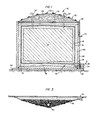
- Figure 1 is a cross sectional view of one installation ;
- Figure 2 is a perspective view partially in cross-sectional of another above ground vault installation;
- Figure 3 is an incomplete view showing a cross-section of an outer liner integrity detection system;
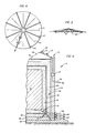
- Figure 4 is a plan of a preferred outer liner integrity detection system;
- Figure 5 is a side view of the preferred outer liner integrity detection system shown in Figure 4; and,
- Figure 6 is a cross-sectional view showing portions of the water and leachate monitoring system of the preferred construction of installation .
- An above
ground vault structure 12, for disposing of or storing hazardous waste and isolating that waste from the surrounding environment, is shown in Figure 1. Thevault 12 is designed to containhazardous waste material 14. As will be explained in more detail below, thewaste material 14 is preferably processed into a dry, solidfied, stable, and load-bearing state before it is placed in thevault 12. - As shown in Figure 1, the
hazardous waste material 14 is immediately surrounded by an inner protective layer 15 which spaces the hazardous waste from aliner 18. In the preferred embodiment, theliner 18 forms a barrier to both water and any leachate that the hazardous waste might produce. To the extent possible, that barrier is designed to be impermeable to both water and potential leachates. An outerprotective layer 20 surrounds theliner 18 and serves as a protection barrier, as well as an infiltration layer. Thelayer 20 is pervious and the top and sides of the liner are designed to permit the gravitational flow and run off of water and other fluids that might enter that layer. The solidifiedwaste material 14,protective layers liner 18 are enclosed and held in place by one or moreperimeter support walls 24. As further shown in Figure 1, the structure also includes aprotective cap 26 at the top of the structure, and asupport base 28 at the bottom. Thecap 26 protects the hazardous waste from the surface environment, and thesupport base 28 forms an impervious barrier between the hazardous waste and the ground water. - The installation includes means for collecting, measuring and removing any water, leachate or other fluids that enter or exit from the
vault 12. Preferably, the structure includes a runoffwater detection system 29, a capintegrity detction system 30, an inner linerintegrity detction system 31 and an outer linerintegrity detction system 32. The runoffwater detection system 29 can collect and measure all of the water which falls on the vault and ultimately runs off the cap. The capintegrity detection system 30 collects and measures any surface water which might leak through the cap and seep through theinfiltration layer 20. The inner linerintegrity detection system 31 collects and measures any leachate that might seep to the bottom of theliner 18. The outer linerintegrity detction system 32 is formed under theouter protection layer 20 to collect and measure any leachate that might flow through the bottom ofliner 18. - As will be explained in more detail below, each of the above detection systems operate on gravitational flow principles. For example, as shown in Figure 1, the outer liner
integrity detection system 32 is placed on an impervious,inclined platform 38 formed over thebase 28. Theinclined platform 38 provides a raised, inclined support for the outer linerintegrity detection system 36. Preferably, theinclined platform 38 and the base 28 are formed of strong but resilient materials which are resistant to earthquakes and lesser seismic tremors and which will accept minor subsidence of the surrounding earth. - As shown in Figure 1, the
base support 28 is formed above thetop ground layer 50 and therefore above the water table and the liquid flow of ground water. As will become more apparent from the discussion below, the structure isolates the waste from both surface and ground water. Placing the hazardous waste and all encapsulating material above the ground on theimpervious base 28 markedly minimizes the risks that contaminant can leach to the ground water. The above ground system also makes it easier to discover any leakage in the vault and take corrective action, if leakages occur. The above ground cell is designed to isolate the hazardous waste from the surrounding environment for indefinite periods. - The structure is designed to dispose of and isolate a wide variety of hazardous waste. Classes of waste that can be safely held by the vault are identified in a later section of this application. Generally, hazardous wastes have a very low load-bearing capacity and exhibit a high incidence of slippage, when in their original form. Often these hazardous wastes include a high concentration of water. If these wastes are mixed with earth, the resultant mixture generally continues to exhibit non-load-bearing characteristics. Therefore, if a load-bearing structure is desired, the waste must be treated.
- A partial perspective view illustrating another structure is shown generally in Figure 2, where like numbers are used to refer to the elements previously discussed with reference to Figure 1. As shown in Figure 2, the structure or
vault 12 is above ground and is covered by acap 26 which can include vegetation. Thecap 26 is designed to promote water run-off, and preferablytop soil 22 andvegetation 23 are placed on thecap 26 to add to the durability of the vault and to minimize the potential for erosion. Thestructure 12 includes a plurality ofpipes water detection system 29, capintegrity detection system 30, inner linerintegrity detection system 31, and outer linerintegrity detection system 32, respectively. The structure also includesvent pipes 37 which allow gas to vent off from the hazardous waste. - In addition to the elements previously described, the preferred embodiment in Figure 2 includes an optional load-
bearing structure 70 to provide increased strength in the cap and to protect further the hazardous waste from the exterior environment. The structure may additionally include ananimal barrier 72 to prevent any burrowing animals from burrowing to or through theliner 18.Barrier 72 could be a wire mesh or a similar barrier which an animal could not penetrate. As an alternative, the cap or other areas surrounding thehazardous waste 14 and itsliner 18 could be laced with a rodenticide. - As shown in Figure 2, the
cap 26, the top surface of theliner 18, the surface of the inner linerintegrity detection system 31, the outer linerintegrity detection system 32 and theplatform 38 are all inclined to promote the rapid run off of any water, fluids or leachates. While the inclination could be in a single direction or in multiple directions, in the preferred embodiment the respective surfaces all incline from their centres outwardly and downwardly. The structure includes water run off-pipes 33 as part of the run-offwater detection system 29 andpipes 34 as part of the capintegrity detection system 30. In addition, the structure includes leachate run-offpipes integrity detection system 31 and outer linerintegrity detection system 32, respectively. Preferably a plurality of these pipes are uniformly spaced about the periphery of the vault, and afluid flow meter 27 can be integrated in the piping to measure fluid flow through each pipe. Any fluid flow through these pipes can be collected so that the fluid can be measured and analyzed. - The design and purpose of the structural elements and the materials from which those elements can be made will now be discussed in further detail.
- The structure can dispose of or store hazardous waste in a viscous liquid, sludge or solid form. In the preferred embodiment, however, the waste is solidified. Depending upon the form of the hazardous waste and material comprising that waste, different methods are available for solidifying the waste. Generally, the waste is solidified by de-watering the waste and then mixing the de-watered waste with a fixing agent. If a hazardous waste is high in water content, standing water is first pumped away from the waste. The presently preferred method of solidification is then to mix the hazardous waste with a fixing agent such as cement flue dust. Cement flue dust has a high surface area and therefore will absorb water and dehydrate the waste. Flue dust will solidify the waste, increase the pH of the waste mixture, convert metals in the waste to insoluble hydroxides, carbonate, and similar compounds and physically absorb non-volatile organics. Further, over a period of several hours, the mixture of hazardous waste and cement flue dust will cure into a hydraulic cement-like substance. Thus, the flue dust acts as a pozzolanic material. The resultant hardening occurs because cement flue dust contains appreciable quantities of anhydrous calcium and metal silicates which dehydrate with water in the hazardous waste to form a stable crystalline material. Once hardened, the hazardous waste will not redisperse, even when exposed to water.
- Under certain circumstances it is desirable to add certain materials to flue dust before mixing the flue dust or other fixing agent with the waste. Some inorganic absorbents have a large surface area and when in contact with the waste will absorb significant quantities of water and oil. Such absorbents lessen the fluidity of the waste and permit the use of lesser quantities of flue dust, often with improved results. Certain organic absorbents will draw the oil in the hazardous waste out from the water, while not reacting with the water. The flue dust then can react primarily with the water and other materials in the waste, often providing an improved solidified waste. By means of example only, calcined rice hulls, activated carbon, and/or granulated calcined oil shale could be added to flue dust to be mixed with inorganic wastes, and activated carbon and/or LOCK SORB could be added with flue to be mixed with organic wastes. The amount of absorbents that should be added to flue dust would depend upon the waste involved and the result desired. Generally, these materials could be added to flue dust in amounts equal to 5-20% of the combined weight of the absorbent material and flue dust.
- For particular hazardous wastes or applications, other types of solidification agents may be used. For instance, coal-fired boiler fly ash can serve as a fixing agent and has similar properties to those of cement flue dust. The properties of fly ash vary from coal to coal, however, and therefore the fixing quantities of fly ash are not always uniform.
- Chemical solidification agents such as CHEMFIX and STABLEX maye be used to solidify the mass of some hazardous wastes. Chemical solidification agents are primarly used for inorganic materials such as metal oxides and salts.
- Regardless of the method of fixation, the resultant solidified waste must be bonded together so that it will resist returning to a fluid state. A sufficient amount of fixing material, such as flue dust, must be added to the material so that it is dry, solidified, and has load-bearing characteristics similar to earth. Generally, the waste, when solidified, will have a bulk density of approximately 1,800 to 2,400 pounds per cubic yard (1070 to 1427 kg/cu m). The exact weight will of course depend upon the particular density of the hazardous waste. Nevertheless, because the solidified waste of most materials will fall within the above range, the design of the vault and the required thicknesses and strength of the various layers which form the vault can be standardized to some degree.
- When placed in the structure, any solidified waste should be compacted to achieve at 95% Proctor or similar soil load-bearing standard. For certain applications it may be preferable to form the hazardous waste in lifts or layers. For other applications, it might be preferable to have several separate compartments with the vault to hold and separate waste which are or might become coreactive. Once placed within the above ground vault, the waste itself becomes a major supporting structural component of the vault.
- The solidified hazardous waste material is surrounded by
protective layer 16.Layer 16 provides a buffering layer between the waste and theliner 18 to prevent reactivity between the waste liner. It also provides an anti-shock cushion, as well as a separate layer which can serve as a construction support mechanism. Thelayer 16 is pervious and preferably is inclined so that it will act as part of an inner linerintegrity detection system 31. Any leachate in the waste or liner will ultimately flow to the outer periphery of thelayer 16 where it can be collected and measured by one ormore pipes 35. Each junction between thepipes 35 and theliner 18 must be carefully sealed to prevent leakage. - By means of example only, the
layer 16 can be made of sand, sand solified with fly ash, constructive fabric materials, and inorganic sorbents such as OIL DRI and SORB ALL. The layer can be formed from one material or a combination several materials, and, if desired, the layer can include perforated run-off pipes to collect and drain any fluids. Thelayer 16 is positioned about the waste by pouring as the lifts of waste are constructed. Generally, thelayer 16 should be thick enough safely to separate the liner from the waste and cushion the waste from shocks during construction. Thelayer 16 also should be sufficiently pervious to permit the free flow of any leachate in the liner. To some degree, the desired thickness will depend upon the weight of the waste and the load-bearing characteristics of the material forming the layer. Typically, the layer would have a thickness in the range of 6 to 18 inches (152 to 457 mm). - The relatively
impermeable liner 18 is designed to isolate the waste from water and to prevent the flow of leachates to or from the wastes. Theliner 18 must be made from material that is resistant to any leachate that might be generated. Generally, clays, asphalts and synthetic sheets are the major types of materials that might be appropriate liners for specific hazardous waste and their respective leachates. Since theliner 18 is expected to function for decades, it must be protected from weathering processes, sharp objects, and biological activities that could penetrate it. - The particular liner used would depend upon the waste and the potential leachates. A solvent cut of high molecular weight aspahlt sprayed upon unwoven fabric mat might serve as a good liner for some waste. The present preferred liners can be made from polyvinylchloride (PVC), low density polyethylene (LDPE), medium density polyethylene (MDPE), ethylene propylene dimer (EPDM), butyl rubber, and chloro-sulphonated polyethylene, such as HYPALON. If desired or necessary for a particular application, the liner can be reinforced. For example, the liner could be laminated to a fabric backing. Generally, plastic liner films should be at least 0.006 inches (0.152 mm)thick and preferably would be in the range of 0.006 to 0.1875 inches (0.152 to 4.762 mm) thick. The liner should be flexible and have the ability to withstand a significant range of climatic conditions.
- The
liner 18 is spaced from the outer linerintegrity detection system 32 by aprotective layer 20.Layer 20 performs many of the same functions as doeslayer 16, and can be made from the materials previously listed forlayer 16. If sand is used for eitherlayer layer 20 acts as a collection pathway to thedetection system 32 and will filter out leachate solids to prevent clogging of the outer linerintegrity detection system 32. Thelayer 20 should cushion theliner 18 from any rocks or pointed articles included as part ofdetection system 32 and should permit water or leachate to flow freely. In the preferred embodiment, the layer, to provide the desired protection, cushioning, and filtration effect, has a thickness in the range of 6 to 8 inches (152 to 203 mm). For most vaults, thelayers - The side and top portions of
layer 20 provide an infiltration channel for the run off of any water which might happen to leak throughcap 26.Layer 20 also provides a channel for any leachate that might leak through the top or sides ofliner 18. As shown in Figure 2, the top and side portions oflayer 20 are separated from the bottom portion oflayer 20 by abarrier 21 which is impervious to water and potential leachates. The top and side portions of thelayer 20 and thebarrier 21 constitute part of the capintegrity detection system 30 and therefore must be constructed to remain stable as water flows through them and as temperatures change. These portions oflayer 20 can be made of a wide variety of porous materials. If necessary, theintegrity detection system 30 can include piping and even water monitors in the interior of the system which would indicate when and generally where any leakage in the cap occurs. Such monitors would enable the repair of the cap before any water leaks through the liner to the hazardous material. As should be apparent, leakage of water to the solidified waste is the main source of contaminated leachate. - The outer liner
integrity detection system 32 should provide a layer which will quickly remove leachate from the vault for many years and preferably never allow the leachate to accumulate. Thesystem 32 may consist of perforated piping embedded in porous media such as gravel or sand. The grain size of the porous medium or media, the pipe placement, the pipe cross-sectional shape, and the size, shape, pattern and screening of the system may vary, depending upon the type of waste, the environmental conditions and the size of the vault. The pipes in the system should be designed so that they are amenable to a periodic cleanout operation. For example, the design should permit snakes or similar mechanical devices to be inserted in the pipes or should allow for the application of a flushing operation. Preferably, the leachate collection layer will be designed to function by gravity alone. If desirable, however, pumping could be added as an ancillary method of leachate removal. - As an example illustrating aspects of the detection systems, the preferred embodiment of the outer liner
integrity detection system 32 is shown in Figures 3, 4 and 5. The leachate system as shown includes gradedgravel 40,separators 41, and perforatescollection pipes 42. Thegravel 40 should be sufficiently large to provide large pore spaces throughout the system. Theperforated collection pipes 42 should be resistant to the potential leachates and should be sufficiently large to allow rapid run-off. The system and piping are inclined to promote gravity flow, and the angle of inclination could be in the range of 1 to 5 degrees, depending upon the size and shape of the vault. - As can be seen in Figures 4 and 5, in the preferred arrangement, the
system 32 includes a plurality of radially extendingpipes 42 and a plurality ofseparators 41. Theseparators 41 are impervious to water and potential leachates and divide thesystem 32 into a number of separate segments. One or more pipes are placed in each separate segment of the system, and in the preferred embodiment each pipe connects with anindividual exit pipe 36 leading through theperimeter wall 24 so that any leachate flowing through the pipe can be collected and measured. Thus, to the extent that any leachate is collected at any pipe, the system will indicate the general section where leakage from the waste material is occurring. This would enable one to determine where a rupture occurs and then limit any remedial action to the area of concern. - Although not shown, it is contemplated that each of
detection systems system 32. For example, separators similar toseparator 41 could be included in the top and side portions oflayer 20, in the bottom portion oflayer 16, and in thecap 26. If desired, collection pipes could also be added to those systems. A plurality ofexit pipes - The
inclined platform 38 serves as an impervious inclined base for the outer linerintegrity detecting system 32 and as an impervious inclined bottom of theinfiltration layer 20. Theplatform 38 provides a head pressure for any fluid in either of these detection systems and serves as an additional safety barrier between the waste or any leachate and the base. The platform preferably is made from clay or asphalt, both of which are impermeable and have excellent sealing characteristics. Theplatform 38 preferably would have a minimum thickness in the range of 1-3 feet (305-914 mm). - The
support base 28 of the vault should be impervious to water and any potential leachates and should provide a strong and solid base for the vault. The base should preferably be made to support at least 1,845 pounds per square foot (9004 kg/sq m). Preferably, the base would be a road base construction with an impervious top layer of clay or asphalt. Depending upon the size of the vault, the base might be made from several layers of a typical road base construction, including graded bases, gravel layers, reinforcement bars, road fabric, and so forth. The base could be made with standard road construction machines and materials. - Solidified waste bearing material will exhibit good vertical load-bearing characteristics when properly confined. However, it is believed that solidified waste does not have strong horizontal stability and strength. Therefore, the structure of the vault must include
perimeter support walls 24 to stop any slippage of the material in a horizontal direction. These structural walls can be made from a wide variety of materials such as precast concrete slabs (reinforced or stressed), cinderblocks, poured concrete, logs, telephone poles, pilings, metal sheets, or even thick clay. To increase the strength of the walls, buttresses, cables, reinforcement bars, and dead man reinforcements migh be added. The perimeter wall may have to withstand lateral pressures of from 200 to 1,000 pounds per square foot (976 to 4880 kg/sq m). The actual value would depend upon the geometry of the structure and the structural cohesiveness of the waste. - The
cap layer 26 will be exposed to the greatest temperature extremes as well as erosion action of sunlight, rain fall, overland water flow, wind and freeze/thaw action. The cap must protect the inner layers from erosive action and yet remain stable itself. To the extent possible, the cap should be designed to be completely impermeable. The main component of thecap 26 can be made from alayer 25 of compacted clays, sparayed urethane foam, asphalt or a reinforced concrete slab. Generally, thecap 26 would have a thickness within the range of 6 inches to 3 feet (152 to 914 mm). Sprayed urethane foam would require ground cover and a positive attachment. Liners similar toliner 18 could be included at the bottom surface of the cap. - As shown in Figure 2 the vault includes a run-off
water detection system 29. Any precipitation on the vault should run-off theinclined cap 26 to the gutter 43 formed about the perimeter of the vault. Thesystem 29 includes a plurality of gravity feddrainage pipes 33 spaced about the periphery of the vault. Eachpipe 33 can include aflow meter 27, such as a vane-type meter, which in turn can be connected to a recording device. The system, therefore, should collect and measure all the precipitation which falls on the vault. - If the top of the vault is to serve as a park or grassy area,
top soil 22 andground cover 23 should be added tolayer 25 of the cap. The top soil and cover combine to serve as a excellent water run-off system and stabilizethe exterior of the vault. If the top of the vault is to be used as a support for a vehicle park, tank farm, or similar structure, aadditonal support structure 70 may be formed under the base, if needed. The load bearing capacity of a vault, without additional support structure, would be approximately 2,800 pounds per square foot (13664 kg/sq m) when the vault contains load-bearing, solidified waste. The cap can be surfaced with a number of exterior construction surfaces, as desired. - Additional fabric can be used to strength the vault. Such fabric typically would be a synthetic fibre fabric, such as construction fabrics for road based construction. Such materials are readily available and can also be supplied as a filter or drainage fabric. Fabrics could be used to add an additional impervious barrier between the cap and the liner or could be used to distribute point loading or cancel stresses.
- The hazardous waste material will be significantly insulated from exterior temperatures. However, even assuming that the material is subject to differences in temperature between 1200 and -20° Fahrenheit (490 and -290C), the thermal expansion and contraction of the waste would not present a significant problem. Solidified hazardous waste in most circumstances would have a coefficient of thermal expansion of approximately 2.5 X 10 in./in./°F (4.5/°C). For hazardous waste having a length of 930 feet (283 m), the largest potential expansion over the range of 1200 to -20° Fahrenheit (490 to -29°C) would be 3-1/2 inches (89 mm). This small degree of expansion should not present significant problems and the effects of the expansion could be further minimized by including expansion joints between vertical and/or horizontal layers of waste. The expansion joints could be formed of sand and similar materials.
- The vault provides a multi-step monitoring system which previously has not been possible with below ground containments. As previously discussed, the system includes four separate detection systems steps which detect fluid leakage before any contamination of the ground or ground water occurs. Referring now to Figure 6, the monitoring system will be briefly explained.
- The first line of safeguard monitoring is provided by run-off
water detection system 29. Under normal operating conditions, all of the precipitation which falls uponvault 12, except that which evaporates, will be collected and measured bysystem 29. By periodically checking the amount of water collected and measured bysystem 29 and comparing that amount with actual precipitation, a water balance can be computed. If the water collected balances with the precipitation, theclay cap 26 is properly protecting the waste from surface water. If the balance is not correct, then there may be a rupture in the cap. By analyzing the measured water run-off, the approximate area of a rupture in the clay cap can be determined. This data can be combined with data collected by the cap integrity detection system, as will be discussed below. - The second monitor, the cap
integrity detection system 30 will collect and measure water and/or leachate only if surface water leaks through the cap 26 (or in flood situations the perimeter walls 24). Thus, ifsystem 29 shows a water imbalance and water is collected atcertain outlet pipes 34 ofsystem 30, it is possible to locate at least roughly where thecap 24 is ruptured by reviewing the data collected bysystems integrity detection system 30 is not contaminated by waste, then the only rupture would be in the cap, and not the liner. If contaminated leachate is collected, then thesystem 30 would indicate that the top or side of the liner was ruptured. Again, the approximate location of the rupture could be determined through an engineering analysis of the data collected bysystem 30. - The third monitor, the inner-liner
integrity detection liner 31, will collect and measure leachate atoutlet pipes 35 only if the liner ruptures at some location abovelayer 16. The system will quickly remove any leachate collected in the liner and also will provide information concerning the location of rupture and the size of the rupture. - Finally, the fourth monitor, the outer-liner
integrity detection liner 32, will collect and measure leachate atoutlet pipes 36 only if the bottom ofliner 18 ruptures. The system again provides for the rapid run-off of any leachate. Any leachate collected is still far removed from the ground and ground water, and the system provides information concerning the location of any ruptures and the degree of contamination. - Through the use of all four detection systems, one can carefully monitor the vault and prevent contamination of the ground and ground water. The system gives an early warning of any problem and allows minor problems to be completely remedied with minimum costs and without any contamination. For example, with the system any ruptures in the cap can be sensed, located, and corrected before any water even reaches the waste itself. To the extent that a line does rupture, the extent of leachate generation can be closely monitored and corrective steps can be taken long before any leachate reaches the ground.
- The above ground vault can be used to dispose of a wide variety of wastes, including the following types: (A) Petroleum Heavy Oils and Tars (e.g., API separator sludges, petroleum still bottoms, oil reclaiming sludges); (B) Aromatic Heavy Oils and Tars (e.g., creosote sludges and tars, scrubber sludges from coke ovens, resorcinol refining sludges, aromatic hydrocarbon still bottoms); (C) Petrochemical Heavy Oils and Tars (e.g., polymer manufacturing tars and sludges, solvent recovery still bottoms, chemical production still bottoms, isocyanate production tars); (D) Halogenated Organic Sludges and tars (e.g., PCB containing sludges, vinyl chloride manufacturing bottoms, dioxin containing sludges, chlorinated solvent manufacturing bottoms); (E) Pesticide/Herbicide Sludges (e.g., arsenic chemicals manufacture, halogenated pesticide manufacture, phosphorous based pesticide manufacture, pesticide/herbicide repackaging); (F) Organic/Inorganic Sludges (e.g., paint sludges, railcar cleanout sludge, dewatering sludges, headed petroleum tank bottoms); (G) Inorganic Sludges (e.g., metal finishing and plating wastes, wastewater treatment sludges, chrome sludges from polymer manufacture, waste sludges from metals smelting); and (H) Contaminated Soils (e.g., massive chemical spills, heavy metals contaminated soils, organic contaminated soils).
- For the above types of waste, the following tables show the preferred methods of solidiferation and preferred materials from which the vault can be made:

- 1 Dependent on concentration any type of dirt contamination.
- The above rating on the choice of liners is made upon a review of the various overall properties of the materials and a comparison of those properties with the desire that the
line 18 be resistant to solvation, plasticization, stress cracking, and chemical attack.

- As is apparent from the above discussion, the structure can safely contain a wide variety of hazardous wastes and can be made in a wide variety of shapes and sizes. The height of the cell will depend upon the amount of hazardous waste to be contained and the asthetic effect desired. Normally the height of solidified waste could be between 5 feet and 20 feet (1524 and 6096 mm).
- The present invention offers many advantages over conventional remedial action such as slurry-wall containment and off-site disposal. The vaults can be built either at private on-site locations or at larger publically available sites. With on site vaults, a generator will not have to pay to transport the wastes, and the public will not be subjected to the hazard that contamination will occur during the transportation step. The waste in the vault is solidified and encapsulated above ground, away from the ground water. The prevention and collection of waste leachate are simplified greatly over the landfill method. Significantly, there is less risk of contaminating ground water because the entire system is above ground, with a larger buffer zone between the waste and the ground and ground water. Access for maintenance is easier, and the top, walls and all fluids in the system can be visually inspected. Any leachate can be detected prior to ground water contamination. Additionally, the leachate collection systems need not be dependent upon pumps but instead can rely upon gravitional flow. Further, the risk of ground water contamination in the event of geological action such as fault slippage, slumping, or any other massive earth movement is reduced.
- When the above ground encapsulation method is used, the site can be cleaned up and made available for other uses. In contrast, when a company uses ground water containment barriers and similar remedial actions, the site must remain useless for other purposes. With vegetation and landscaping techniques, above ground encapsulation can enhance the asthetics of an area and serve as bird sanctuaries, car parks, or anything within the creative capabilities of designers and planners. Above ground encapsulation is safe, simple and an economic remedial method that can be used at on-site locaations and abandoned waste sites.
Claims (22)
Priority Applications (1)
| Application Number | Priority Date | Filing Date | Title |
|---|---|---|---|
| AT84304298T ATE41798T1 (en) | 1983-06-29 | 1984-06-25 | DEVICE AND METHOD FOR CONTAINING HAZARDOUS WASTE. |
Applications Claiming Priority (2)
| Application Number | Priority Date | Filing Date | Title |
|---|---|---|---|
| US509137 | 1983-06-29 | ||
| US06/509,137 US4464081A (en) | 1983-06-29 | 1983-06-29 | Process and structure for storing and isolating hazardous waste |
Publications (3)
| Publication Number | Publication Date |
|---|---|
| EP0130773A2 true EP0130773A2 (en) | 1985-01-09 |
| EP0130773A3 EP0130773A3 (en) | 1986-06-04 |
| EP0130773B1 EP0130773B1 (en) | 1989-03-29 |
Family
ID=24025437
Family Applications (1)
| Application Number | Title | Priority Date | Filing Date |
|---|---|---|---|
| EP84304298A Expired EP0130773B1 (en) | 1983-06-29 | 1984-06-25 | Installation and method for containing hazardous waste |
Country Status (6)
| Country | Link |
|---|---|
| US (1) | US4464081A (en) |
| EP (1) | EP0130773B1 (en) |
| JP (1) | JPS6087101A (en) |
| AT (1) | ATE41798T1 (en) |
| CA (1) | CA1225219A (en) |
| DE (1) | DE3477496D1 (en) |
Cited By (8)
| Publication number | Priority date | Publication date | Assignee | Title |
|---|---|---|---|---|
| DE3505687A1 (en) * | 1985-02-19 | 1986-08-21 | Basf Ag, 6700 Ludwigshafen | SEALING SCREEN FOR DEPONIES |
| EP0204895A2 (en) * | 1985-06-14 | 1986-12-17 | Philipp Holzmann AG | Container for dumpable wastes |
| EP0226880A1 (en) * | 1985-12-21 | 1987-07-01 | Nukem GmbH | Process for conditioning of water-soluble, special waste |
| DE3616377A1 (en) * | 1986-05-15 | 1987-11-19 | Zueblin Ag | Arrangement and method of sealing landfills and operating sites containing environmentally hazardous substances |
| EP0303591A2 (en) * | 1987-08-12 | 1989-02-15 | Alpine Baugesellschaft Mbh | Method for the treatment of dumped material, dump receptacle for carrying out said method and removable cover for a dump receptacle |
| FR2641559A1 (en) * | 1989-01-06 | 1990-07-13 | Lecomte Michel | Method and installation for decompressing the hydrostatic pressure exerted on the sealing cladding of a concrete volume buried in the ground |
| EP0390377A2 (en) * | 1989-03-30 | 1990-10-03 | Westinghouse Electric Corporation | Inspectable vault system for the disposal of radioactive waste formed from vault cells having a liquid collection system |
| DE4213585A1 (en) * | 1992-04-24 | 1993-10-28 | Siemens Ag | Landfill monitoring device and leak detection method |
Families Citing this family (60)
| Publication number | Priority date | Publication date | Assignee | Title |
|---|---|---|---|---|
| US5116414A (en) * | 1981-10-26 | 1992-05-26 | Battelle Memorial Institute | Long-term control of root growth |
| US4618284A (en) * | 1984-05-24 | 1986-10-21 | Marks Alvin M | Device and method for the reclamation of polluted land areas |
| DE3423438A1 (en) * | 1984-06-26 | 1986-04-30 | Klaus Dr. 6242 Kronberg Wiemer | DEVICE FOR DETERMINATING SEPARATE WATER AND GAS FROM LANDFILLS |
| US4784802A (en) * | 1984-07-05 | 1988-11-15 | Westinghouse Electric Corp. | Nuclear waste disposal site |
| DE3445127A1 (en) * | 1984-12-11 | 1986-06-19 | Karl Dipl.-Ing. Dr.techn. 6238 Hofheim Grund | SOLE CONSTRUCTION FOR A WASTE DISCHARGE |
| US4650086A (en) * | 1984-12-19 | 1987-03-17 | Morrison Jr James B | Portable hazardous waste container |
| DE3508824A1 (en) * | 1985-03-13 | 1986-09-18 | Erhard Dipl.-Ing. Beyerl | Landfill site for environmentally polluting substance |
| US4682492A (en) * | 1985-07-08 | 1987-07-28 | Green Marion C | Means and method for detecting leaks in tanks |
| US4584102A (en) * | 1985-09-05 | 1986-04-22 | Bogart John D | Process for the biological degradation of hazardous waste by-products |
| AT384963B (en) * | 1985-09-19 | 1988-02-10 | Oemv Ag | METHOD FOR NON-DAY SITU SEALING OR SEALING OR RECOVERY OF OLD DESTINATIONS, i.e. OLD, PROTECTED WASTE DEPOSITS, SOG. OLD BAD AND CONTAMINATED LOCATIONS |
| US4778628A (en) * | 1986-05-15 | 1988-10-18 | The United States Of America As Represented By The United States Department Of Energy | Underground waste barrier structure |
| US4696599A (en) * | 1986-07-14 | 1987-09-29 | Waste Resource Associates, Inc. | Secure landfill and method of operating a landfill for hazardous waste |
| US4867604A (en) * | 1986-11-06 | 1989-09-19 | Bell Gordon L | Unified monitoring system for hazardous and toxic waste |
| US4741395A (en) * | 1986-12-08 | 1988-05-03 | Reed Robert W | Vent-well system |
| JPH0611604B2 (en) * | 1987-02-24 | 1994-02-16 | 守 小林 | Waste site structure |
| US4908129A (en) * | 1987-05-27 | 1990-03-13 | Dyckerhoff & Widmann Aktiengesellschaft | Impervious layer formation process and landfill adsorption system |
| US4787772A (en) * | 1987-06-26 | 1988-11-29 | Eljen Corporation | Device for detecting leaks in underground fluid tanks |
| US4842774A (en) * | 1987-08-07 | 1989-06-27 | The United States Of America As Represented By The United States Department Of Energy | Pyramiding tumuli waste disposal site and method of construction thereof |
| US4844840A (en) * | 1987-08-14 | 1989-07-04 | Bechtel Group, Inc. | Method and structure for hazardous waste containment |
| DE3802086C1 (en) * | 1988-01-25 | 1989-08-03 | Alfred Kunz Gmbh & Co, 8000 Muenchen, De | |
| US5356452A (en) * | 1988-06-07 | 1994-10-18 | Fahey Robert E | Method and apparatus for reclaiming waste material |
| US4875805A (en) * | 1988-09-06 | 1989-10-24 | Robert Gross | Toxic waste storage facility |
| CA2005376C (en) * | 1989-12-13 | 1996-11-19 | James Russell Baird | Subductive waste disposal method |
| US5010776A (en) * | 1989-05-04 | 1991-04-30 | Iit Research Institute | Environmental contamination detection and analyzing system and method |
| US5030033A (en) * | 1989-09-12 | 1991-07-09 | Heintzelman Stephen D | Material containment system |
| US4973195A (en) * | 1989-10-27 | 1990-11-27 | Bbj Company, Inc. | Storage facility for hazardous waste and the like |
| GB8926116D0 (en) * | 1989-11-18 | 1990-01-10 | Tarmac Econowaste Ltd | Lining of landfill sites |
| US5068912A (en) * | 1990-06-04 | 1991-11-26 | Unisys Corp. | Track gauges for aligning and focussing the imaging system in a high speed document handling system |
| US5201609A (en) * | 1991-07-23 | 1993-04-13 | Johnson Research And Development Corp. | Cellular landfill process and apparatus |
| JP3331364B2 (en) * | 1992-04-27 | 2002-10-07 | 繁樹 森 | Industrial waste pit |
| US5340238A (en) * | 1992-08-04 | 1994-08-23 | Tanknology Corporation International | Method and apparatus for testing above ground liquid storage tanks for leaks |
| US5387741A (en) * | 1993-07-30 | 1995-02-07 | Shuttle; Anthony J. | Method and apparatus for subterranean containment of hazardous waste material |
| US5419655A (en) * | 1993-08-02 | 1995-05-30 | Westinghouse Electric Corporation | Collection of liquid from below-ground location |
| US5388931A (en) * | 1993-10-18 | 1995-02-14 | Carlson; Robert J. | Cutoff wall system to isolate contaminated soil |
| AU2763795A (en) * | 1995-06-05 | 1996-12-24 | Morris E. Lewis | Method and apparatus for leak prevention and remediation in storage tank systems |
| US5599139A (en) * | 1995-06-07 | 1997-02-04 | The Tensar Corporation | Method of constructing a liner system and waste containment facility incorporating same |
| JP2869431B2 (en) * | 1995-11-17 | 1999-03-10 | 株式会社環境アセスメントセンター | Underground dam |
| US5890840A (en) * | 1995-12-08 | 1999-04-06 | Carter, Jr.; Ernest E. | In situ construction of containment vault under a radioactive or hazardous waste site |
| US5632715A (en) * | 1995-12-15 | 1997-05-27 | J. R. Simplot Company | In situ immobilization of metals in waste stacks and waste stack affected zones |
| DE19617902C1 (en) * | 1996-05-03 | 1997-07-10 | Empac Verpackungs Gmbh | Polymer film liner for bulk material container |
| US6071043A (en) * | 1998-03-13 | 2000-06-06 | Hunt; James R. | System for securing landfills |
| US6238137B1 (en) * | 1999-04-01 | 2001-05-29 | New Mexico Tech Research Foundation | Containment system for spills |
| US6213685B1 (en) * | 1999-11-04 | 2001-04-10 | Peter W. Ingalls | Mechanical boot system |
| KR20020013168A (en) * | 2000-08-11 | 2002-02-20 | 엄기형 | A drainage construction method of ground floor |
| US6749368B2 (en) * | 2000-09-05 | 2004-06-15 | Daniel B. Stephens & Associates, Inc. | Design, monitoring and control of soil carburetors for degradation of volatile compounds |
| NL1016327C2 (en) * | 2000-10-04 | 2002-04-08 | Insulation Consulting & Procur | Pre-insulated storage tank for cold liquids. |
| US6595723B2 (en) * | 2001-08-31 | 2003-07-22 | Peter J. Ianniello | Conversion of gypsum stacks to waste containment facilities and related construction and business methods |
| JP4697671B2 (en) * | 2007-06-04 | 2011-06-08 | 株式会社大林組 | Hazardous substance separation and removal equipment |
| WO2009100529A1 (en) * | 2008-02-11 | 2009-08-20 | Marc-Antoine Pelletier | Gas and liquid extraction system and method |
| JP5398710B2 (en) * | 2008-06-19 | 2014-01-29 | 国立大学法人群馬大学 | Artificial multiple barriers for radioactive waste disposal facilities. |
| MY161488A (en) * | 2009-11-20 | 2017-04-14 | Red Leaf Resources Inc | Subsidence control systems |
| US20120045285A1 (en) * | 2010-08-23 | 2012-02-23 | Oil Well Closure And Protection As | Offshore structure |
| WO2012025911A2 (en) * | 2010-08-24 | 2012-03-01 | Thierry Labrosse | Method for manufacturing a tank, and storage tank |
| JP5250724B1 (en) * | 2013-03-14 | 2013-07-31 | 株式会社フジコーポレーション | Bottom plate structure of final disposal site |
| JP5250725B1 (en) * | 2013-03-14 | 2013-07-31 | 株式会社フジコーポレーション | Vertical wall structure of final disposal site |
| CN103195103B (en) * | 2013-04-10 | 2015-07-22 | 中广核工程有限公司 | Drainage system of solid waste disposal site |
| CN106061616B (en) * | 2014-01-28 | 2020-09-25 | 红叶资源公司 | Long term storage of waste by adsorption with high surface area materials |
| US9901963B2 (en) * | 2016-06-07 | 2018-02-27 | Tom McBride | System for groundwater protection |
| CN106836171B (en) * | 2017-03-24 | 2018-05-04 | 中国矿业大学(北京) | Opencast coal mine dump water level real-time monitoring system and its foundation and application method |
| CN110902184A (en) * | 2019-11-14 | 2020-03-24 | 安徽环嘉天一再生资源有限公司 | Renewable resource recycling and classifying system based on big data |
Citations (7)
| Publication number | Priority date | Publication date | Assignee | Title |
|---|---|---|---|---|
| CH418989A (en) * | 1964-10-06 | 1966-08-15 | Metallwerk Ag | Process for the production of a foundation for a standing metal tank that is sealed against seepage water |
| CH587389A5 (en) * | 1974-10-30 | 1977-04-29 | Spaeth Peter | Underground toxic waste disposal in sealed containers - in excavation with watertight base compacted backfill and returned topsoil |
| CH616124A5 (en) * | 1976-04-15 | 1980-03-14 | Grennard Alf H | Method for the safe subterranean storage of cold products and corresponding storage system |
| US4335978A (en) * | 1981-04-07 | 1982-06-22 | Mutch Robert D | Induced intragradient system for secure landfill |
| US4352601A (en) * | 1980-08-18 | 1982-10-05 | Stabatrol Corporation | Permanent bin for temporary storage of hazardous materials |
| US4362434A (en) * | 1980-10-28 | 1982-12-07 | Stabatrol Corporation | Permanent disposal vault for hazardous chemical waste materials |
| US4375930A (en) * | 1980-12-03 | 1983-03-08 | Stabatrol Corp. | Permanent disposal vault for containers |
Family Cites Families (5)
| Publication number | Priority date | Publication date | Assignee | Title |
|---|---|---|---|---|
| US3136135A (en) * | 1961-08-22 | 1964-06-09 | Shell Oil Co | Shipping liquefied gases |
| US3505820A (en) * | 1967-12-28 | 1970-04-14 | Phillips Petroleum Co | Leak detection for lined reservoirs |
| US3701262A (en) * | 1970-10-12 | 1972-10-31 | Systems Capital Corp | Means for the underground storage of liquified gas |
| US4425743A (en) * | 1980-11-17 | 1984-01-17 | Joseph Bartur | Inground fluid storage tank and method of erection thereof |
| US4430021A (en) * | 1981-11-23 | 1984-02-07 | Ecological Professional Industries, Inc. | Secure chemical waste landfill |
-
1983
- 1983-06-29 US US06/509,137 patent/US4464081A/en not_active Expired - Lifetime
-
1984
- 1984-06-14 CA CA000456629A patent/CA1225219A/en not_active Expired
- 1984-06-25 AT AT84304298T patent/ATE41798T1/en active
- 1984-06-25 DE DE8484304298T patent/DE3477496D1/en not_active Expired
- 1984-06-25 EP EP84304298A patent/EP0130773B1/en not_active Expired
- 1984-06-29 JP JP59134990A patent/JPS6087101A/en active Pending
Patent Citations (7)
| Publication number | Priority date | Publication date | Assignee | Title |
|---|---|---|---|---|
| CH418989A (en) * | 1964-10-06 | 1966-08-15 | Metallwerk Ag | Process for the production of a foundation for a standing metal tank that is sealed against seepage water |
| CH587389A5 (en) * | 1974-10-30 | 1977-04-29 | Spaeth Peter | Underground toxic waste disposal in sealed containers - in excavation with watertight base compacted backfill and returned topsoil |
| CH616124A5 (en) * | 1976-04-15 | 1980-03-14 | Grennard Alf H | Method for the safe subterranean storage of cold products and corresponding storage system |
| US4352601A (en) * | 1980-08-18 | 1982-10-05 | Stabatrol Corporation | Permanent bin for temporary storage of hazardous materials |
| US4362434A (en) * | 1980-10-28 | 1982-12-07 | Stabatrol Corporation | Permanent disposal vault for hazardous chemical waste materials |
| US4375930A (en) * | 1980-12-03 | 1983-03-08 | Stabatrol Corp. | Permanent disposal vault for containers |
| US4335978A (en) * | 1981-04-07 | 1982-06-22 | Mutch Robert D | Induced intragradient system for secure landfill |
Cited By (15)
| Publication number | Priority date | Publication date | Assignee | Title |
|---|---|---|---|---|
| WO1986004943A1 (en) * | 1985-02-19 | 1986-08-28 | Bilfinger + Berger Bauaktiengesellschaft | Protective screen for waste matter |
| DE3505687A1 (en) * | 1985-02-19 | 1986-08-21 | Basf Ag, 6700 Ludwigshafen | SEALING SCREEN FOR DEPONIES |
| US4753551A (en) * | 1985-02-19 | 1988-06-28 | Basf Aktiengesellschaft | Sealing screen for waste dumps |
| EP0204895A3 (en) * | 1985-06-14 | 1988-03-16 | Philipp Holzmann Ag | Container for dumpable wastes |
| EP0204895A2 (en) * | 1985-06-14 | 1986-12-17 | Philipp Holzmann AG | Container for dumpable wastes |
| EP0226880A1 (en) * | 1985-12-21 | 1987-07-01 | Nukem GmbH | Process for conditioning of water-soluble, special waste |
| DE3616377A1 (en) * | 1986-05-15 | 1987-11-19 | Zueblin Ag | Arrangement and method of sealing landfills and operating sites containing environmentally hazardous substances |
| DE3616377C2 (en) * | 1986-05-15 | 1998-07-02 | Zueblin Ag | Device for sealing storage and operating facilities containing environmentally hazardous substances |
| EP0303591A2 (en) * | 1987-08-12 | 1989-02-15 | Alpine Baugesellschaft Mbh | Method for the treatment of dumped material, dump receptacle for carrying out said method and removable cover for a dump receptacle |
| EP0303591A3 (en) * | 1987-08-12 | 1990-03-28 | Alpine Baugesellschaft Mbh | Method for the treatment of dumped material, dump receptacle for carrying out said method and removable cover for a dump receptacle |
| FR2641559A1 (en) * | 1989-01-06 | 1990-07-13 | Lecomte Michel | Method and installation for decompressing the hydrostatic pressure exerted on the sealing cladding of a concrete volume buried in the ground |
| EP0390377A2 (en) * | 1989-03-30 | 1990-10-03 | Westinghouse Electric Corporation | Inspectable vault system for the disposal of radioactive waste formed from vault cells having a liquid collection system |
| EP0390377A3 (en) * | 1989-03-30 | 1991-06-05 | Westinghouse Electric Corporation | Inspectable vault system for the disposal of radioactive waste formed from vault cells having a liquid collection system |
| DE4213585A1 (en) * | 1992-04-24 | 1993-10-28 | Siemens Ag | Landfill monitoring device and leak detection method |
| US5570974A (en) * | 1992-04-24 | 1996-11-05 | Siemens Aktiengesellschaft | Assembly for monitoring a landfill and a method of locating leaks |
Also Published As
| Publication number | Publication date |
|---|---|
| US4464081A (en) | 1984-08-07 |
| EP0130773B1 (en) | 1989-03-29 |
| EP0130773A3 (en) | 1986-06-04 |
| CA1225219A (en) | 1987-08-11 |
| DE3477496D1 (en) | 1989-05-03 |
| JPS6087101A (en) | 1985-05-16 |
| ATE41798T1 (en) | 1989-04-15 |
Similar Documents
| Publication | Publication Date | Title |
|---|---|---|
| EP0130773B1 (en) | Installation and method for containing hazardous waste | |
| EP2764164B1 (en) | Fluid containment and management system | |
| Bouazza et al. | Geosynthetics in waste containment facilities: recent advances | |
| US4810131A (en) | Landfill leachate collection and leak detection sump system | |
| US5201609A (en) | Cellular landfill process and apparatus | |
| US4844840A (en) | Method and structure for hazardous waste containment | |
| US6599058B1 (en) | Landfill leachate collection apparatus | |
| KR100459077B1 (en) | A Method for construction of Waste landfills | |
| Fluet Jr et al. | A review of geosynthetic liner system technology | |
| Slimak | Landfill disposal systems | |
| JP2000015209A (en) | Waste disposal facility | |
| US10145079B1 (en) | Berm and method of manufacturing a berm | |
| LAND | CANCELLED | |
| Schneck | Technical standards for the construction of hazardous waste landfills in Germany documented at the hazardous waste landfill site at Raindorf | |
| Broder | Building a secondary containment system | |
| Gerber et al. | In Situ Remediation Integrated Program: Evaluation and Assessment of Containment Technology | |
| Hartley | Technical Resource Document: Design, Construction, and Operation of Hazardous and Non-hazardous Waste Surface Impoundments | |
| Cretan et al. | SEALING SOLUTIONS FOR COMPLIANT LANDFILL FOUNDATION, ACTIVITIES UNDERTAKEN TO PROTECT ENVIRONMENTAL FACTORS IN OPERATING AND AFTER CLOSING A LANDFILL | |
| Broder | Containment of fertilizers and pesticides at retail operations | |
| Legge et al. | Pollution prevention awareness for municipal managers in South Africa: urban and rural engineering | |
| Authority | Containment of Fertilizers and Pesticides at Retail Operations | |
| Gossow | The refurbishment of contaminated sites and high-safety waste dump technology | |
| Plant | Supplemental Waste Plan | |
| Corcoran et al. | Unique geosynthetic liner system for uranium mill tailings disposal | |
| Paulica et al. | DESIGNING AN INFRASTRUCTURE FOR THE HANDLING OF LARGE QUANTITIES OF OILY WASTE-PART II |
Legal Events
| Date | Code | Title | Description |
|---|---|---|---|
| PUAI | Public reference made under article 153(3) epc to a published international application that has entered the european phase |
Free format text: ORIGINAL CODE: 0009012 |
|
| AK | Designated contracting states |
Designated state(s): AT BE CH DE FR GB IT LI LU NL SE |
|
| PUAL | Search report despatched |
Free format text: ORIGINAL CODE: 0009013 |
|
| AK | Designated contracting states |
Kind code of ref document: A3 Designated state(s): AT BE CH DE FR GB IT LI LU NL SE |
|
| 17P | Request for examination filed |
Effective date: 19860603 |
|
| 17Q | First examination report despatched |
Effective date: 19871207 |
|
| GRAA | (expected) grant |
Free format text: ORIGINAL CODE: 0009210 |
|
| AK | Designated contracting states |
Kind code of ref document: B1 Designated state(s): AT BE CH DE FR GB IT LI LU NL SE |
|
| REF | Corresponds to: |
Ref document number: 41798 Country of ref document: AT Date of ref document: 19890415 Kind code of ref document: T |
|
| ITF | It: translation for a ep patent filed |
Owner name: JACOBACCI & PERANI S.P.A. |
|
| REF | Corresponds to: |
Ref document number: 3477496 Country of ref document: DE Date of ref document: 19890503 |
|
| ET | Fr: translation filed | ||
| PLBE | No opposition filed within time limit |
Free format text: ORIGINAL CODE: 0009261 |
|
| STAA | Information on the status of an ep patent application or granted ep patent |
Free format text: STATUS: NO OPPOSITION FILED WITHIN TIME LIMIT |
|
| 26N | No opposition filed | ||
| ITTA | It: last paid annual fee | ||
| PGFP | Annual fee paid to national office [announced via postgrant information from national office to epo] |
Ref country code: SE Payment date: 19920518 Year of fee payment: 9 |
|
| PGFP | Annual fee paid to national office [announced via postgrant information from national office to epo] |
Ref country code: CH Payment date: 19920519 Year of fee payment: 9 Ref country code: AT Payment date: 19920519 Year of fee payment: 9 |
|
| PGFP | Annual fee paid to national office [announced via postgrant information from national office to epo] |
Ref country code: LU Payment date: 19920520 Year of fee payment: 9 |
|
| PGFP | Annual fee paid to national office [announced via postgrant information from national office to epo] |
Ref country code: BE Payment date: 19920522 Year of fee payment: 9 |
|
| PGFP | Annual fee paid to national office [announced via postgrant information from national office to epo] |
Ref country code: NL Payment date: 19920630 Year of fee payment: 9 |
|
| EPTA | Lu: last paid annual fee | ||
| PG25 | Lapsed in a contracting state [announced via postgrant information from national office to epo] |
Ref country code: LU Free format text: LAPSE BECAUSE OF NON-PAYMENT OF DUE FEES Effective date: 19930625 Ref country code: AT Effective date: 19930625 |
|
| PG25 | Lapsed in a contracting state [announced via postgrant information from national office to epo] |
Ref country code: SE Effective date: 19930626 |
|
| PG25 | Lapsed in a contracting state [announced via postgrant information from national office to epo] |
Ref country code: LI Effective date: 19930630 Ref country code: CH Effective date: 19930630 Ref country code: BE Effective date: 19930630 |
|
| BERE | Be: lapsed |
Owner name: ROLLINS ENVIRONMENTAL SERVICES INC. Effective date: 19930630 |
|
| PG25 | Lapsed in a contracting state [announced via postgrant information from national office to epo] |
Ref country code: NL Effective date: 19940101 |
|
| NLV4 | Nl: lapsed or anulled due to non-payment of the annual fee | ||
| REG | Reference to a national code |
Ref country code: CH Ref legal event code: PL |
|
| EUG | Se: european patent has lapsed |
Ref document number: 84304298.7 Effective date: 19940110 |
|
| PGFP | Annual fee paid to national office [announced via postgrant information from national office to epo] |
Ref country code: FR Payment date: 19970521 Year of fee payment: 14 |
|
| PGFP | Annual fee paid to national office [announced via postgrant information from national office to epo] |
Ref country code: DE Payment date: 19970522 Year of fee payment: 14 |
|
| PGFP | Annual fee paid to national office [announced via postgrant information from national office to epo] |
Ref country code: GB Payment date: 19970527 Year of fee payment: 14 |
|
| PG25 | Lapsed in a contracting state [announced via postgrant information from national office to epo] |
Ref country code: GB Free format text: LAPSE BECAUSE OF NON-PAYMENT OF DUE FEES Effective date: 19980625 |
|
| GBPC | Gb: european patent ceased through non-payment of renewal fee |
Effective date: 19980625 |
|
| PG25 | Lapsed in a contracting state [announced via postgrant information from national office to epo] |
Ref country code: FR Free format text: LAPSE BECAUSE OF NON-PAYMENT OF DUE FEES Effective date: 19990226 |
|
| PG25 | Lapsed in a contracting state [announced via postgrant information from national office to epo] |
Ref country code: DE Free format text: LAPSE BECAUSE OF NON-PAYMENT OF DUE FEES Effective date: 19990401 |
|
| REG | Reference to a national code |
Ref country code: FR Ref legal event code: ST |