EP0130744A2 - Trennsieb und Verfahren zu seiner Herstellung - Google Patents
Trennsieb und Verfahren zu seiner Herstellung Download PDFInfo
- Publication number
- EP0130744A2 EP0130744A2 EP84304200A EP84304200A EP0130744A2 EP 0130744 A2 EP0130744 A2 EP 0130744A2 EP 84304200 A EP84304200 A EP 84304200A EP 84304200 A EP84304200 A EP 84304200A EP 0130744 A2 EP0130744 A2 EP 0130744A2
- Authority
- EP
- European Patent Office
- Prior art keywords
- frame
- screen
- wall
- screen cloth
- assembly
- Prior art date
- Legal status (The legal status is an assumption and is not a legal conclusion. Google has not performed a legal analysis and makes no representation as to the accuracy of the status listed.)
- Withdrawn
Links
Images
Classifications
-
- B—PERFORMING OPERATIONS; TRANSPORTING
- B07—SEPARATING SOLIDS FROM SOLIDS; SORTING
- B07B—SEPARATING SOLIDS FROM SOLIDS BY SIEVING, SCREENING, SIFTING OR BY USING GAS CURRENTS; SEPARATING BY OTHER DRY METHODS APPLICABLE TO BULK MATERIAL, e.g. LOOSE ARTICLES FIT TO BE HANDLED LIKE BULK MATERIAL
- B07B1/00—Sieving, screening, sifting, or sorting solid materials using networks, gratings, grids, or the like
- B07B1/46—Constructional details of screens in general; Cleaning or heating of screens
- B07B1/48—Stretching devices for screens
-
- B—PERFORMING OPERATIONS; TRANSPORTING
- B07—SEPARATING SOLIDS FROM SOLIDS; SORTING
- B07B—SEPARATING SOLIDS FROM SOLIDS BY SIEVING, SCREENING, SIFTING OR BY USING GAS CURRENTS; SEPARATING BY OTHER DRY METHODS APPLICABLE TO BULK MATERIAL, e.g. LOOSE ARTICLES FIT TO BE HANDLED LIKE BULK MATERIAL
- B07B1/00—Sieving, screening, sifting, or sorting solid materials using networks, gratings, grids, or the like
- B07B1/46—Constructional details of screens in general; Cleaning or heating of screens
- B07B1/4609—Constructional details of screens in general; Cleaning or heating of screens constructional details of screening surfaces or meshes
- B07B1/4618—Manufacturing of screening surfaces
-
- B—PERFORMING OPERATIONS; TRANSPORTING
- B29—WORKING OF PLASTICS; WORKING OF SUBSTANCES IN A PLASTIC STATE IN GENERAL
- B29C—SHAPING OR JOINING OF PLASTICS; SHAPING OF MATERIAL IN A PLASTIC STATE, NOT OTHERWISE PROVIDED FOR; AFTER-TREATMENT OF THE SHAPED PRODUCTS, e.g. REPAIRING
- B29C37/00—Component parts, details, accessories or auxiliary operations, not covered by group B29C33/00 or B29C35/00
- B29C37/0078—Measures or configurations for obtaining anchoring effects in the contact areas between layers
- B29C37/0082—Mechanical anchoring
- B29C37/0085—Mechanical anchoring by means of openings in the layers
-
- B—PERFORMING OPERATIONS; TRANSPORTING
- B29—WORKING OF PLASTICS; WORKING OF SUBSTANCES IN A PLASTIC STATE IN GENERAL
- B29C—SHAPING OR JOINING OF PLASTICS; SHAPING OF MATERIAL IN A PLASTIC STATE, NOT OTHERWISE PROVIDED FOR; AFTER-TREATMENT OF THE SHAPED PRODUCTS, e.g. REPAIRING
- B29C65/00—Joining or sealing of preformed parts, e.g. welding of plastics materials; Apparatus therefor
- B29C65/02—Joining or sealing of preformed parts, e.g. welding of plastics materials; Apparatus therefor by heating, with or without pressure
- B29C65/44—Joining a heated non plastics element to a plastics element
-
- B—PERFORMING OPERATIONS; TRANSPORTING
- B29—WORKING OF PLASTICS; WORKING OF SUBSTANCES IN A PLASTIC STATE IN GENERAL
- B29C—SHAPING OR JOINING OF PLASTICS; SHAPING OF MATERIAL IN A PLASTIC STATE, NOT OTHERWISE PROVIDED FOR; AFTER-TREATMENT OF THE SHAPED PRODUCTS, e.g. REPAIRING
- B29C65/00—Joining or sealing of preformed parts, e.g. welding of plastics materials; Apparatus therefor
- B29C65/56—Joining or sealing of preformed parts, e.g. welding of plastics materials; Apparatus therefor using mechanical means or mechanical connections, e.g. form-fits
- B29C65/64—Joining a non-plastics element to a plastics element, e.g. by force
-
- B—PERFORMING OPERATIONS; TRANSPORTING
- B29—WORKING OF PLASTICS; WORKING OF SUBSTANCES IN A PLASTIC STATE IN GENERAL
- B29C—SHAPING OR JOINING OF PLASTICS; SHAPING OF MATERIAL IN A PLASTIC STATE, NOT OTHERWISE PROVIDED FOR; AFTER-TREATMENT OF THE SHAPED PRODUCTS, e.g. REPAIRING
- B29C66/00—General aspects of processes or apparatus for joining preformed parts
- B29C66/01—General aspects dealing with the joint area or with the area to be joined
- B29C66/05—Particular design of joint configurations
- B29C66/10—Particular design of joint configurations particular design of the joint cross-sections
- B29C66/11—Joint cross-sections comprising a single joint-segment, i.e. one of the parts to be joined comprising a single joint-segment in the joint cross-section
- B29C66/112—Single lapped joints
-
- B—PERFORMING OPERATIONS; TRANSPORTING
- B29—WORKING OF PLASTICS; WORKING OF SUBSTANCES IN A PLASTIC STATE IN GENERAL
- B29C—SHAPING OR JOINING OF PLASTICS; SHAPING OF MATERIAL IN A PLASTIC STATE, NOT OTHERWISE PROVIDED FOR; AFTER-TREATMENT OF THE SHAPED PRODUCTS, e.g. REPAIRING
- B29C66/00—General aspects of processes or apparatus for joining preformed parts
- B29C66/01—General aspects dealing with the joint area or with the area to be joined
- B29C66/05—Particular design of joint configurations
- B29C66/10—Particular design of joint configurations particular design of the joint cross-sections
- B29C66/11—Joint cross-sections comprising a single joint-segment, i.e. one of the parts to be joined comprising a single joint-segment in the joint cross-section
- B29C66/114—Single butt joints
-
- B—PERFORMING OPERATIONS; TRANSPORTING
- B29—WORKING OF PLASTICS; WORKING OF SUBSTANCES IN A PLASTIC STATE IN GENERAL
- B29C—SHAPING OR JOINING OF PLASTICS; SHAPING OF MATERIAL IN A PLASTIC STATE, NOT OTHERWISE PROVIDED FOR; AFTER-TREATMENT OF THE SHAPED PRODUCTS, e.g. REPAIRING
- B29C66/00—General aspects of processes or apparatus for joining preformed parts
- B29C66/01—General aspects dealing with the joint area or with the area to be joined
- B29C66/05—Particular design of joint configurations
- B29C66/303—Particular design of joint configurations the joint involving an anchoring effect
- B29C66/3032—Particular design of joint configurations the joint involving an anchoring effect making use of protrusions or cavities belonging to at least one of the parts to be joined
- B29C66/30325—Particular design of joint configurations the joint involving an anchoring effect making use of protrusions or cavities belonging to at least one of the parts to be joined making use of cavities belonging to at least one of the parts to be joined
-
- B—PERFORMING OPERATIONS; TRANSPORTING
- B29—WORKING OF PLASTICS; WORKING OF SUBSTANCES IN A PLASTIC STATE IN GENERAL
- B29C—SHAPING OR JOINING OF PLASTICS; SHAPING OF MATERIAL IN A PLASTIC STATE, NOT OTHERWISE PROVIDED FOR; AFTER-TREATMENT OF THE SHAPED PRODUCTS, e.g. REPAIRING
- B29C66/00—General aspects of processes or apparatus for joining preformed parts
- B29C66/50—General aspects of joining tubular articles; General aspects of joining long products, i.e. bars or profiled elements; General aspects of joining single elements to tubular articles, hollow articles or bars; General aspects of joining several hollow-preforms to form hollow or tubular articles
- B29C66/51—Joining tubular articles, profiled elements or bars; Joining single elements to tubular articles, hollow articles or bars; Joining several hollow-preforms to form hollow or tubular articles
- B29C66/53—Joining single elements to tubular articles, hollow articles or bars
- B29C66/534—Joining single elements to open ends of tubular or hollow articles or to the ends of bars
- B29C66/5346—Joining single elements to open ends of tubular or hollow articles or to the ends of bars said single elements being substantially flat
-
- B—PERFORMING OPERATIONS; TRANSPORTING
- B29—WORKING OF PLASTICS; WORKING OF SUBSTANCES IN A PLASTIC STATE IN GENERAL
- B29C—SHAPING OR JOINING OF PLASTICS; SHAPING OF MATERIAL IN A PLASTIC STATE, NOT OTHERWISE PROVIDED FOR; AFTER-TREATMENT OF THE SHAPED PRODUCTS, e.g. REPAIRING
- B29C66/00—General aspects of processes or apparatus for joining preformed parts
- B29C66/50—General aspects of joining tubular articles; General aspects of joining long products, i.e. bars or profiled elements; General aspects of joining single elements to tubular articles, hollow articles or bars; General aspects of joining several hollow-preforms to form hollow or tubular articles
- B29C66/61—Joining from or joining on the inside
- B29C66/612—Making circumferential joints
-
- B—PERFORMING OPERATIONS; TRANSPORTING
- B29—WORKING OF PLASTICS; WORKING OF SUBSTANCES IN A PLASTIC STATE IN GENERAL
- B29C—SHAPING OR JOINING OF PLASTICS; SHAPING OF MATERIAL IN A PLASTIC STATE, NOT OTHERWISE PROVIDED FOR; AFTER-TREATMENT OF THE SHAPED PRODUCTS, e.g. REPAIRING
- B29C69/00—Combinations of shaping techniques not provided for in a single one of main groups B29C39/00 - B29C67/00, e.g. associations of moulding and joining techniques; Apparatus therefore
-
- B—PERFORMING OPERATIONS; TRANSPORTING
- B29—WORKING OF PLASTICS; WORKING OF SUBSTANCES IN A PLASTIC STATE IN GENERAL
- B29C—SHAPING OR JOINING OF PLASTICS; SHAPING OF MATERIAL IN A PLASTIC STATE, NOT OTHERWISE PROVIDED FOR; AFTER-TREATMENT OF THE SHAPED PRODUCTS, e.g. REPAIRING
- B29C70/00—Shaping composites, i.e. plastics material comprising reinforcements, fillers or preformed parts, e.g. inserts
- B29C70/68—Shaping composites, i.e. plastics material comprising reinforcements, fillers or preformed parts, e.g. inserts by incorporating or moulding on preformed parts, e.g. inserts or layers, e.g. foam blocks
- B29C70/82—Forcing wires, nets or the like partially or completely into the surface of an article, e.g. by cutting and pressing
-
- B—PERFORMING OPERATIONS; TRANSPORTING
- B29—WORKING OF PLASTICS; WORKING OF SUBSTANCES IN A PLASTIC STATE IN GENERAL
- B29C—SHAPING OR JOINING OF PLASTICS; SHAPING OF MATERIAL IN A PLASTIC STATE, NOT OTHERWISE PROVIDED FOR; AFTER-TREATMENT OF THE SHAPED PRODUCTS, e.g. REPAIRING
- B29C48/00—Extrusion moulding, i.e. expressing the moulding material through a die or nozzle which imparts the desired form; Apparatus therefor
- B29C48/03—Extrusion moulding, i.e. expressing the moulding material through a die or nozzle which imparts the desired form; Apparatus therefor characterised by the shape of the extruded material at extrusion
- B29C48/09—Articles with cross-sections having partially or fully enclosed cavities, e.g. pipes or channels
-
- B—PERFORMING OPERATIONS; TRANSPORTING
- B29—WORKING OF PLASTICS; WORKING OF SUBSTANCES IN A PLASTIC STATE IN GENERAL
- B29C—SHAPING OR JOINING OF PLASTICS; SHAPING OF MATERIAL IN A PLASTIC STATE, NOT OTHERWISE PROVIDED FOR; AFTER-TREATMENT OF THE SHAPED PRODUCTS, e.g. REPAIRING
- B29C48/00—Extrusion moulding, i.e. expressing the moulding material through a die or nozzle which imparts the desired form; Apparatus therefor
- B29C48/03—Extrusion moulding, i.e. expressing the moulding material through a die or nozzle which imparts the desired form; Apparatus therefor characterised by the shape of the extruded material at extrusion
- B29C48/12—Articles with an irregular circumference when viewed in cross-section, e.g. window profiles
-
- B—PERFORMING OPERATIONS; TRANSPORTING
- B29—WORKING OF PLASTICS; WORKING OF SUBSTANCES IN A PLASTIC STATE IN GENERAL
- B29C—SHAPING OR JOINING OF PLASTICS; SHAPING OF MATERIAL IN A PLASTIC STATE, NOT OTHERWISE PROVIDED FOR; AFTER-TREATMENT OF THE SHAPED PRODUCTS, e.g. REPAIRING
- B29C48/00—Extrusion moulding, i.e. expressing the moulding material through a die or nozzle which imparts the desired form; Apparatus therefor
- B29C48/15—Extrusion moulding, i.e. expressing the moulding material through a die or nozzle which imparts the desired form; Apparatus therefor incorporating preformed parts or layers, e.g. extrusion moulding around inserts
-
- B—PERFORMING OPERATIONS; TRANSPORTING
- B29—WORKING OF PLASTICS; WORKING OF SUBSTANCES IN A PLASTIC STATE IN GENERAL
- B29C—SHAPING OR JOINING OF PLASTICS; SHAPING OF MATERIAL IN A PLASTIC STATE, NOT OTHERWISE PROVIDED FOR; AFTER-TREATMENT OF THE SHAPED PRODUCTS, e.g. REPAIRING
- B29C66/00—General aspects of processes or apparatus for joining preformed parts
- B29C66/01—General aspects dealing with the joint area or with the area to be joined
- B29C66/05—Particular design of joint configurations
- B29C66/10—Particular design of joint configurations particular design of the joint cross-sections
- B29C66/11—Joint cross-sections comprising a single joint-segment, i.e. one of the parts to be joined comprising a single joint-segment in the joint cross-section
- B29C66/112—Single lapped joints
- B29C66/1122—Single lap to lap joints, i.e. overlap joints
-
- B—PERFORMING OPERATIONS; TRANSPORTING
- B29—WORKING OF PLASTICS; WORKING OF SUBSTANCES IN A PLASTIC STATE IN GENERAL
- B29C—SHAPING OR JOINING OF PLASTICS; SHAPING OF MATERIAL IN A PLASTIC STATE, NOT OTHERWISE PROVIDED FOR; AFTER-TREATMENT OF THE SHAPED PRODUCTS, e.g. REPAIRING
- B29C66/00—General aspects of processes or apparatus for joining preformed parts
- B29C66/70—General aspects of processes or apparatus for joining preformed parts characterised by the composition, physical properties or the structure of the material of the parts to be joined; Joining with non-plastics material
- B29C66/71—General aspects of processes or apparatus for joining preformed parts characterised by the composition, physical properties or the structure of the material of the parts to be joined; Joining with non-plastics material characterised by the composition of the plastics material of the parts to be joined
-
- B—PERFORMING OPERATIONS; TRANSPORTING
- B29—WORKING OF PLASTICS; WORKING OF SUBSTANCES IN A PLASTIC STATE IN GENERAL
- B29C—SHAPING OR JOINING OF PLASTICS; SHAPING OF MATERIAL IN A PLASTIC STATE, NOT OTHERWISE PROVIDED FOR; AFTER-TREATMENT OF THE SHAPED PRODUCTS, e.g. REPAIRING
- B29C66/00—General aspects of processes or apparatus for joining preformed parts
- B29C66/80—General aspects of machine operations or constructions and parts thereof
- B29C66/83—General aspects of machine operations or constructions and parts thereof characterised by the movement of the joining or pressing tools
- B29C66/832—Reciprocating joining or pressing tools
- B29C66/8322—Joining or pressing tools reciprocating along one axis
-
- B—PERFORMING OPERATIONS; TRANSPORTING
- B29—WORKING OF PLASTICS; WORKING OF SUBSTANCES IN A PLASTIC STATE IN GENERAL
- B29K—INDEXING SCHEME ASSOCIATED WITH SUBCLASSES B29B, B29C OR B29D, RELATING TO MOULDING MATERIALS OR TO MATERIALS FOR MOULDS, REINFORCEMENTS, FILLERS OR PREFORMED PARTS, e.g. INSERTS
- B29K2105/00—Condition, form or state of moulded material or of the material to be shaped
- B29K2105/06—Condition, form or state of moulded material or of the material to be shaped containing reinforcements, fillers or inserts
- B29K2105/20—Inserts
- B29K2105/206—Meshes, lattices or nets
-
- B—PERFORMING OPERATIONS; TRANSPORTING
- B29—WORKING OF PLASTICS; WORKING OF SUBSTANCES IN A PLASTIC STATE IN GENERAL
- B29K—INDEXING SCHEME ASSOCIATED WITH SUBCLASSES B29B, B29C OR B29D, RELATING TO MOULDING MATERIALS OR TO MATERIALS FOR MOULDS, REINFORCEMENTS, FILLERS OR PREFORMED PARTS, e.g. INSERTS
- B29K2705/00—Use of metals, their alloys or their compounds, for preformed parts, e.g. for inserts
-
- B—PERFORMING OPERATIONS; TRANSPORTING
- B29—WORKING OF PLASTICS; WORKING OF SUBSTANCES IN A PLASTIC STATE IN GENERAL
- B29L—INDEXING SCHEME ASSOCIATED WITH SUBCLASS B29C, RELATING TO PARTICULAR ARTICLES
- B29L2012/00—Frames
-
- B—PERFORMING OPERATIONS; TRANSPORTING
- B29—WORKING OF PLASTICS; WORKING OF SUBSTANCES IN A PLASTIC STATE IN GENERAL
- B29L—INDEXING SCHEME ASSOCIATED WITH SUBCLASS B29C, RELATING TO PARTICULAR ARTICLES
- B29L2031/00—Other particular articles
- B29L2031/14—Filters
-
- B—PERFORMING OPERATIONS; TRANSPORTING
- B29—WORKING OF PLASTICS; WORKING OF SUBSTANCES IN A PLASTIC STATE IN GENERAL
- B29L—INDEXING SCHEME ASSOCIATED WITH SUBCLASS B29C, RELATING TO PARTICULAR ARTICLES
- B29L2031/00—Other particular articles
- B29L2031/737—Articles provided with holes, e.g. grids, sieves
Definitions
- the field of the present invention is screening structures and their method of manufacture.
- the Hansen device is uncomplicated and inexpensive but does require partial disassembly of the screening device for replacement of the screen. Caught between providing a very rigid supporting structure for the screen assemblies and providing an easily disassembled system, most modern commercial screening systems generally have exhibited either overcomplicated placement mechanisms or overcomplicated disassembly and assembly requirements.
- the present invention pertains to screening structures and their manufacture.
- Screen assemblies of the present invention include frames which can be expanded by inflation in a manner controlled in large part by the very structure of the frame. This directed expansion may also act to fix the assembly within a screening device.
- screen assemblies are available which do not require expensive fabricating techniques, are not required to carry fully tensioned loads when not in position within the screening device, and are easily placed, retained and removed from the screening device. The ease of fabrication and the structural simplicity result in low cost screen assemblies and screening devices with low maintenance and replacement costs.
- Screen assemblies fabricated to create a device of the present invention may be made by heating the screen cloth with a thermoplastic screen frame pressed thereagainst. Concentric electrodes can be employed to properly heat the screen cloth for fusion of the frame material. When the screen frame begins to fuse, the cloth is embedded within the frame, at which time the assembly may be cooled. This procedure locks the screen cloth into the body of the frame member such that tension on the screen cloth is easily withstood. Furthermore, the act of moving the screen cloth into the fused portion of the frame resulted in a lip being formed through plastic deformation of the inner edge of the frame. As the lip is relatively thin, it provides a force transition area to reduce the stress concentration at the intersection of the screen cloth with the frame member. As the screen cloth is embedded in the lip, abrasion at this critical location is reduced.
- the screen frame may be fabricated, if desired, from extruded stock. As substantial deformation is contemplated in use of the device, tolerance requirements are minimized. Furthermore, the screen need not be tensioned prior to assembly and can, therefore, rely in part on the structural rigidity of the housing for support. These factors make possible inexpensive fabrication of screen assemblies through the use of such extruded stock. When thermoplastic materials are used, the fabrication steps are also greatly simplified. The abutting ends of the extrusion may be easily fused to form the frame.
- a separate rigid frame member may be employed with the expansible frame.
- This member may be used to provide a base of sufficient rigidity for directing the expansion of the expansible frame to advantageously tension the screen.
- the rigidity of this frame member can be incorporated into the expansible frame where desired.
- the present invention advantageously reduces the need for complicated and expensive frame members and assembly procedures and makes placement and removal of the screen assemblies in the associated screening devices very easy. Furthermore, abrasion and vibrational loading forces are appropriately controlled. Accordingly, it is an object of the present invention to provide improved screening assemblies, screening devices incorporating such assemblies and methods of manufacture. Other and further objects and advantages will appear hereinafter.
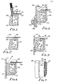
- a screening device including a substantially cylindrical housing 10 is contemplated for use with the present invention.
- a device specifically structured for the screen assembly of the present invention is shown in Figures 3 and 4 as including an inwardly extending flange 12 which is conveniently welded to the substantially cylindrical housing 10.
- the housing 10 need not be exactly cylindrical because of the expandable nature of the resulting screen assembly to fit or even round out any slightly ovular shape of the cylindrical cross-section.
- a screen assembly Positioned within the substantially cylindrical housing 10 of the screening device is a screen assembly.
- the screen assembly is deflated in Figure 3 and is inflated in Figure 4.
- This screen assembly includes an expansible frame, generally designated 14.
- This frame 14 is generally rectangular in cross-section, as can be seen in the figures.
- the overall shape of the frame 14 is a closed planar curve which may approximate a rectangular shape but is a circular curve in the most preferred embodiment. That is to say, the frame is circular and generally lies in a plane such that the screen cloth of the assembly will lie in a plane as well.
- the maximum outside diameter of the frame 14 is relatively equal to the nominal inside diameter of the housing 10 for easy placement and removal of the screen assembly when in the deflated condition. Thus, it can be positioned as seen in the figures.
- the frame 14 is preferably of a thermoplastic elastomer which is resiliently expansible.
- the thermoplastic nature of the material is employed principally for ease of fabrication as will be discussed below.
- the resilient and expansible nature of the material is designed to accommodate some deformation when subjected to inflation.
- the structure must also be rigid enough in thick cross-section to provide the required structural support.
- the proper selection of material and corresponding structural thicknesses useful for any given use of the present invention must be determined from empirical analysis and conventional design considerations.
- the somewhat rectangular cross-section of the frame 14 is defined by four integral walls.
- a first wall 16 is relatively thin in relationship to the remaining portions of the structure and is located on the inside of the frame 14.
- a second or outer wall 18 is thicker than the inner wall 16 by at least two times. In this way, inflation of the frame 14 results in controlled deformation with less resistance to deformation presented by the inner wall 16 than by the outer wall 18.
- Third and fourth walls 20 and 22 extend between the walls 16 and 18 to complete the rectangular cross-section.
- the walls 20 and 22 need not be as thick as outer wall 18 or as thin as inner wall 16. That is to say, there is no need for the walls 20 and 22 to be as deformable as the inner wall 16 or as inflexible as the outer wall 18.
- the upper wall 20 should be of sufficient rigidity to prevent extreme distortion when the screen assembly is inflated and the screen tensioned.
- the hollow cavity defined by walls 16, 18, 20 and 22 is maintained in a closed state such that the device may be inflated as intended.
- an upstanding ridge 24 is used for convenient assembly with the screen cloth.
- a lip 26 extends inwardly in relatively thin section.
- the lip 26 provides a transitional area where the screen cloth is received.
- the lip 26 becomes progressively thicker, it joins with the main body of the frame 14.
- the increase in structural resistance to flexure is provided such that there is no one point or line flexure is provided such that there is no one point or line of intersection between the exposed screen cloth and the inner edge of the frame 14 where flexure forces are concentrated. In this manner, screen life at this difficult intersection is enhanced.
- a rigid frame member 28 is, as can be seen in the figures, positioned concentrically inwardly of the frame 14.
- This frame member 28 is relatively rigid compared to the frame 14 and may conveniently be a metallic ring.
- the width of the metallic ring 28 is preferably shorter than the height of the inside wall of the frame 14. For improved screen life, it is preferred that the upper edge of the metallic ring 28 not come in contact with the screen cloth itself, which would result in excessive stresses and abrasions.
- the ring 28 may, on the other hand, extend downwardly below the bottom of the frame 14 but would serve no purpose specifically related to the present invention and would make insertion to the proper depth within the frame 14 more difficult.
- the frame member 28 is preferably of sufficient overall width to provide an interference fit with the inner wall 16 of the frame 14 when in the uninflated state. With such an interference fit, the frame 14 and the frame member 28 may be handled without specifically making provision for the retention of the two parts together. However, the fit need only be close so that the frame 14, when inflated, will come into contact with the frame member 28 and still have sufficient expansion to tension the screen.
- the screen assembly is completed by the addition of screen cloth 30 which, in a preferred embodiment employing thermoplastic elastomer, is embedded within the upstanding wide ridge 24.
- the excess screen cloth 30 which extends radially outwardly from the upstanding wide ridge 24 is removed.
- the screen cloth 30 may be of any useful mesh size as determined by the intended use of the assembly.
- a means for admitting and retaining pressure is employed.
- This means is illustrated in Figure 1 in the preferred embodiment as a valve stem 32.
- the valve stem is positioned through the upper wall 20.
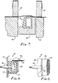
- An alternate location and assembly for the valve stem is illustrated in Figures 8 and 9.
- a hole is provided in the cylindrical housing 10 to accommodate the outward extension of the valve in this second embodiment.
- the illustrated valve 32 is a pneumatic device. However, it is contemplated within the present invention to employ whatever useful fluid may be chosen. Shop air is normally the most convenient fluid. However, for high load applications as might be required by very heavy screen cloth, hydraulic fluid may be employed. It is also contemplated that a chemically reactive mixture in fluid form may be introduced into the hollow cavity which expands and solidifies into a permanently expanded state.
- an outer surface is provided on the wall 18 which is tapered inwardly as it approaches the wall 20 to which the screen 30 is anchored.
- a taper 36 is illustrated in Figure 3 in the uninflated assembly. Inflation of the frame 14 causes the inner wall 16 to force itself against the frame member 28. The relative strength of the frame member 28 is such that it will resist such expansion of this inner wall. Consequently, the only remaining area for expansion is the space defined between the inner side of the cylindrical housing 10 and the taper of the outer wall 18. This room for expansion is greatest at the area adjacent the upper wall 20 containing the screen 30. Consequently, the frame 14 will move outwardly to contact and press against the cylindrical housing 10. This motion results in a tensioning of the screen cloth 30 and in the retention of the frame 14 in the cylindrical housing 10. Thus, rigid placement and screen tensioning is effected by mere inflation of the assembly.
- the wall 18 is also beveled to form a bevel surface 37.
- the bevel moves the location of the maximum outside diameter up and away from the corner of the screening device where the screen frame must fit.
- the corner treatment of the screening device is less critical as is the diameter of the frame itself.
- a taper on the top at 38 is employed to give added space for trimming of the screen once assembled with the frame.
- the rigid placement also provides structural rigidity to the frame member through its association with the cylindrical housing 10.
- the material and structural size of the frame 14 must be such that it can, with inflation, expand against the cylindrical housing 10.
- the frame member 28 must be of sufficient rigidity to resist expansion in an inward direction so as to insure the proper end result.
- a preferred embodiment for the frame member 28 includes a cross section of 1" x 1/4" for a ring approximately 44 inches in diameter.
- Fabrication of the frame 14 is, in the preferred embodiment, by extrusion.
- Extrusion is a relatively continuous process and is considered inexpensive when used in a commercial application.
- the extrusion is cut to the appropriate length. It is then formed into a circle and joined at a seam 39 as seen in Figure 5.
- the seam 39 is preferably formed by fusing both ends of the extruded section with rapid placement together.
- An alternate seam 39 is illustrated in Figure 9 as having a bevel.
- the bevel performs two primary functions. First, it provides an increased weld surface. Secondly, it provides access to the outer wall 18 of the frame 14 for the alternate placement of the valve 32 as shown in Figure 8 prior to welding of the two ends together.
- the frame 14 employed with a 100 mesh screen has an overall height of 1.437 in., an overall width across the top of .78 in. and a taper 36 of 10° on the outside surface thereof.
- the inner wall 16 is .093 in. thick
- the outer wall 18 is .41 in. thick at the widest point
- the third and fourth walls 20 and 22 are somewhat tapered with fourth wall 22 having a minimum thickness of .156 in.
- the upstanding wide ridge 24 is .50 in. in width and .046 in. in height.
- the top tapers downwardly from the back of the wide ridge 24 at a 20° angle.
- the bevel 37 is taken at 30° from the vertical and has a height of .187 in.
- Figure 6 illustrates an alternate embodiment which is compatible with screening devices presently on the market.
- the variation is simply to employ a cylindrical housing 10a which is provided in segments with outwardly extending flanges 48a which receive the inwardly extending flange 12a. The assembly is then held together by clamp bands 50a.
- a preferred method for the manufacture of screens of the present invention employs the set up as illustrated in Figure 7.
- the Figure is illustrated to be a cross section taken of a circular arrangement.
- Each of the components illustrated with the exception of the screen cloth is circular in arrangement about a common axis.
- the process employed is designed to provide maximum bonding integrity between the screen cloth and the frame. At the same time, inexpensive material and minimum labor is contemplated for the manufacture of each screen.
- a first circular electrode 52 is arranged about the outside of the frame while a concentric circular electrode 50 is positioned about the inside of the screen frame.
- An electrical potential of four volts is then designed to be applied between the electrodes 52 and 54 resulting in a current of approximately 2200 amps moving radially across the annular portion of the screen cloth extending between the electrodes.
- the current is applied for approximately 48 seconds; however, this time can vary substantially with variations in screen cloth, mesh size, thermoplastic material and the like.
- the sizable current required has a tendency to burn holes in the screen cloth if full contact is not made. Therefore, backup, insulated blocks 56 and 58 are employed below the screen cloth 30 to allow the electrodes 52 and 54 to press against the screen cloth before current is applied to achieve sufficient contact to avoid burning and arcing. Additionally, it may be advantageous to place some tension on the screen cloth, particularly with fine mesh screens, to insure proper bonding. This may be accomplished by placing a light pressure in the upward direction on the screen frame 14 by its supporting jig 60. The light pressure may allow additional plastic to move upwardly through the screen cloth as it is fused to insure proper bonding.
- the voltage is withdrawn and the heat required to fuse the thermoplastic quickly dissipates.
- the newly assembled screen is thus immediately able to be withdrawn for trimming of the excess screen cloth outwardly of the wide ridge 24.
- the valve assembly 32 is assembled with the frame 14 on the upper wall 20 of the frame outwardly of the trimmed screen 30.
- a thermoplastic tube is attached to the frame 14 by heating the frame 14 and one end of the thermoplastic tube.
- the frame may be heated with a heat gun while the tube may be placed against a hot plate.
- the tube and frame are then quickly fused together.
- a hole is then drilled through the upper wall 20 of the frame 14 as guided by the bore of the tube.
- a valve is then forced into the tube to complete the valve assembly 32.
Landscapes
- Engineering & Computer Science (AREA)
- Mechanical Engineering (AREA)
- Manufacturing & Machinery (AREA)
- Chemical & Material Sciences (AREA)
- Composite Materials (AREA)
- Folding Of Thin Sheet-Like Materials, Special Discharging Devices, And Others (AREA)
- Combined Means For Separation Of Solids (AREA)
Applications Claiming Priority (4)
| Application Number | Priority Date | Filing Date | Title |
|---|---|---|---|
| US51025683A | 1983-07-01 | 1983-07-01 | |
| US510380 | 1983-07-01 | ||
| US06/510,380 US4568455A (en) | 1983-07-01 | 1983-07-01 | Screening device |
| US510256 | 1990-04-17 |
Publications (2)
| Publication Number | Publication Date |
|---|---|
| EP0130744A2 true EP0130744A2 (de) | 1985-01-09 |
| EP0130744A3 EP0130744A3 (de) | 1986-03-05 |
Family
ID=27056841
Family Applications (1)
| Application Number | Title | Priority Date | Filing Date |
|---|---|---|---|
| EP19840304200 Withdrawn EP0130744A3 (de) | 1983-07-01 | 1984-06-21 | Trennsieb und Verfahren zu seiner Herstellung |
Country Status (1)
| Country | Link |
|---|---|
| EP (1) | EP0130744A3 (de) |
Cited By (5)
| Publication number | Priority date | Publication date | Assignee | Title |
|---|---|---|---|---|
| FR2599993A1 (fr) * | 1986-06-17 | 1987-12-18 | Kanzaki Paper Mfg Co Ltd | Chassis pour dispositif de tamisage sous pression |
| EP0218315A3 (de) * | 1985-06-13 | 1988-05-11 | Thule United Limited | Siebklemmvorichtung |
| WO1992019392A1 (en) * | 1991-05-06 | 1992-11-12 | Sweco, Inc. | Circular vibratory screen separator |
| EP1068942A1 (de) * | 1998-04-06 | 2001-01-17 | Aichi Co., Ltd. | Verfahren zum Anspannen einer Folie an einem Rahmen, und Verfahren zur Herstellung eines Sitzes durch dieses Anspannungsverfahren |
| WO2008042729A1 (en) | 2006-09-29 | 2008-04-10 | M-I Llc | Composite screen with integral inflatable seal |
Family Cites Families (5)
| Publication number | Priority date | Publication date | Assignee | Title |
|---|---|---|---|---|
| FR883576A (fr) * | 1941-07-01 | 1943-07-08 | Franz Zimmer S Erben K G | Procédé et dispositif pour fixer avec une tension uniforme des tissus ou treillis sur un châssis |
| US3176843A (en) * | 1962-01-09 | 1965-04-06 | Entoleter | Screen tensioner |
| US3255810A (en) * | 1962-05-14 | 1966-06-14 | Francis W Rowbottam | Screen assembly and method of making the same |
| AT239161B (de) * | 1963-07-18 | 1965-03-25 | Erich O Riedel | Vorrichtung zum Spannen von Sieb- und Filtergeweben |
| AT329474B (de) * | 1974-02-25 | 1976-05-10 | Oesterr Amerikan Magnesit | Spannvorrichtung fur siebboden |
-
1984
- 1984-06-21 EP EP19840304200 patent/EP0130744A3/de not_active Withdrawn
Cited By (8)
| Publication number | Priority date | Publication date | Assignee | Title |
|---|---|---|---|---|
| EP0218315A3 (de) * | 1985-06-13 | 1988-05-11 | Thule United Limited | Siebklemmvorichtung |
| FR2599993A1 (fr) * | 1986-06-17 | 1987-12-18 | Kanzaki Paper Mfg Co Ltd | Chassis pour dispositif de tamisage sous pression |
| WO1992019392A1 (en) * | 1991-05-06 | 1992-11-12 | Sweco, Inc. | Circular vibratory screen separator |
| US5226546A (en) * | 1991-05-06 | 1993-07-13 | Sweco, Incorporated | Circular vibratory screen separator |
| US5255789A (en) * | 1991-05-06 | 1993-10-26 | Janssens Eduard X J | Circular vibratory screen separator |
| EP1068942A1 (de) * | 1998-04-06 | 2001-01-17 | Aichi Co., Ltd. | Verfahren zum Anspannen einer Folie an einem Rahmen, und Verfahren zur Herstellung eines Sitzes durch dieses Anspannungsverfahren |
| WO2008042729A1 (en) | 2006-09-29 | 2008-04-10 | M-I Llc | Composite screen with integral inflatable seal |
| EP2066459A4 (de) * | 2006-09-29 | 2014-09-17 | Mi Llc | Verbundbildschirm mit integralem aufblasbarem verschluss |
Also Published As
| Publication number | Publication date |
|---|---|
| EP0130744A3 (de) | 1986-03-05 |
Similar Documents
| Publication | Publication Date | Title |
|---|---|---|
| US4568455A (en) | Screening device | |
| US4832317A (en) | Fluid pressure devices | |
| EP0295393B1 (de) | Montage der Endplatten für eine Luftfeder | |
| US5730444A (en) | Seal with embedded garter spring | |
| EP0130744A2 (de) | Trennsieb und Verfahren zu seiner Herstellung | |
| FI81538B (fi) | Expanderbar locksvetsningskolv. | |
| GB2119674A (en) | Air filter element | |
| US4238039A (en) | Railway car coupler wear liner | |
| US7005025B2 (en) | Welded item | |
| US3915775A (en) | Method of bonding a plastic tension ring for a screen | |
| JP2000193007A (ja) | 板バネ一体型コアおよびその製造方法 | |
| GB1572399A (en) | Plastic container | |
| EP0259449A1 (de) | Formdichtungsgestaltung zum einkapseln einer glasscheibe mit einer flachdichtung | |
| JP4733106B2 (ja) | ベントピース及び前記ベントピースが装着された金型 | |
| JPH06137426A (ja) | ダイアフラム部材及びその製作方法 | |
| ES2319194T3 (es) | Molde de vulcanizacion de tipo dividido. | |
| US4989394A (en) | Press plunger having separable press ring | |
| US4582470A (en) | Apparatus for vulcanizing a tire | |
| US4555055A (en) | Method of making centrifuge screen baskets | |
| US5958173A (en) | Method of fabricating a filter screen | |
| EP0210679A1 (de) | Verfahren und Vorrichtung zum Stumpfschweissen eines extrudierten Behälterkörpers und seines Deckels mit Heizspiegeln | |
| US3236411A (en) | Expansion tank | |
| GB2335477A (en) | Coil spring insulator and method of molding the same | |
| US3473660A (en) | Tensioning means for circular separator screens | |
| AU2003203731A1 (en) | Collapsible mechanism for molding a tire bead |
Legal Events
| Date | Code | Title | Description |
|---|---|---|---|
| PUAI | Public reference made under article 153(3) epc to a published international application that has entered the european phase |
Free format text: ORIGINAL CODE: 0009012 |
|
| AK | Designated contracting states |
Designated state(s): BE DE FR GB IT NL |
|
| PUAL | Search report despatched |
Free format text: ORIGINAL CODE: 0009013 |
|
| AK | Designated contracting states |
Kind code of ref document: A3 Designated state(s): BE DE FR GB IT NL |
|
| 17P | Request for examination filed |
Effective date: 19860811 |
|
| 17Q | First examination report despatched |
Effective date: 19870720 |
|
| STAA | Information on the status of an ep patent application or granted ep patent |
Free format text: STATUS: THE APPLICATION IS DEEMED TO BE WITHDRAWN |
|
| 18D | Application deemed to be withdrawn |
Effective date: 19880201 |
|
| RIN1 | Information on inventor provided before grant (corrected) |
Inventor name: RACINE, BILL ALBERT Inventor name: HUBER, GENE ALFRED Inventor name: SALLADIN, GERALD PAUL |