EP0129468A1 - Verfahren zum Vorwärmen eines Behälters und der inneren Bauteile eines mit flüssigem Metall gekühlten Kernreaktors mit schnellen Neutronen, sowie Vorwärmungseinrichtungen - Google Patents
Verfahren zum Vorwärmen eines Behälters und der inneren Bauteile eines mit flüssigem Metall gekühlten Kernreaktors mit schnellen Neutronen, sowie Vorwärmungseinrichtungen Download PDFInfo
- Publication number
- EP0129468A1 EP0129468A1 EP84401186A EP84401186A EP0129468A1 EP 0129468 A1 EP0129468 A1 EP 0129468A1 EP 84401186 A EP84401186 A EP 84401186A EP 84401186 A EP84401186 A EP 84401186A EP 0129468 A1 EP0129468 A1 EP 0129468A1
- Authority
- EP
- European Patent Office
- Prior art keywords
- tank
- preheating
- gas
- slab
- reactor
- Prior art date
- Legal status (The legal status is an assumption and is not a legal conclusion. Google has not performed a legal analysis and makes no representation as to the accuracy of the status listed.)
- Granted
Links
- 238000000034 method Methods 0.000 title claims abstract description 20
- 239000007788 liquid Substances 0.000 title claims description 12
- 230000007935 neutral effect Effects 0.000 claims abstract description 15
- 229910001338 liquidmetal Inorganic materials 0.000 claims abstract description 14
- 230000008018 melting Effects 0.000 claims abstract description 5
- 238000002844 melting Methods 0.000 claims abstract description 5
- 239000007789 gas Substances 0.000 claims description 69
- DGAQECJNVWCQMB-PUAWFVPOSA-M Ilexoside XXIX Chemical compound C[C@@H]1CC[C@@]2(CC[C@@]3(C(=CC[C@H]4[C@]3(CC[C@@H]5[C@@]4(CC[C@@H](C5(C)C)OS(=O)(=O)[O-])C)C)[C@@H]2[C@]1(C)O)C)C(=O)O[C@H]6[C@@H]([C@H]([C@@H]([C@H](O6)CO)O)O)O.[Na+] DGAQECJNVWCQMB-PUAWFVPOSA-M 0.000 claims description 45
- 229910052708 sodium Inorganic materials 0.000 claims description 45
- 239000011734 sodium Substances 0.000 claims description 45
- IJGRMHOSHXDMSA-UHFFFAOYSA-N Atomic nitrogen Chemical compound N#N IJGRMHOSHXDMSA-UHFFFAOYSA-N 0.000 claims description 33
- 229910052757 nitrogen Inorganic materials 0.000 claims description 17
- 238000010438 heat treatment Methods 0.000 claims description 14
- 238000007664 blowing Methods 0.000 claims description 11
- 238000009434 installation Methods 0.000 claims description 8
- 238000003303 reheating Methods 0.000 abstract description 7
- 238000001816 cooling Methods 0.000 description 5
- 230000002093 peripheral effect Effects 0.000 description 4
- 229910052751 metal Inorganic materials 0.000 description 2
- 239000002184 metal Substances 0.000 description 2
- 230000001869 rapid Effects 0.000 description 2
- 238000007789 sealing Methods 0.000 description 2
- 230000035939 shock Effects 0.000 description 2
- 230000008023 solidification Effects 0.000 description 2
- 238000007711 solidification Methods 0.000 description 2
- 230000000712 assembly Effects 0.000 description 1
- 238000000429 assembly Methods 0.000 description 1
- 239000011324 bead Substances 0.000 description 1
- 238000005485 electric heating Methods 0.000 description 1
- 238000000605 extraction Methods 0.000 description 1
- 230000008014 freezing Effects 0.000 description 1
- 238000007710 freezing Methods 0.000 description 1
- 239000000446 fuel Substances 0.000 description 1
- 230000001939 inductive effect Effects 0.000 description 1
- 239000011261 inert gas Substances 0.000 description 1
- QJGQUHMNIGDVPM-UHFFFAOYSA-N nitrogen group Chemical group [N] QJGQUHMNIGDVPM-UHFFFAOYSA-N 0.000 description 1
- 125000006850 spacer group Chemical group 0.000 description 1
- 230000008646 thermal stress Effects 0.000 description 1
- 238000011144 upstream manufacturing Methods 0.000 description 1
Images


Classifications
-
- G—PHYSICS
- G21—NUCLEAR PHYSICS; NUCLEAR ENGINEERING
- G21D—NUCLEAR POWER PLANT
- G21D1/00—Details of nuclear power plant
- G21D1/02—Arrangements of auxiliary equipment
-
- Y—GENERAL TAGGING OF NEW TECHNOLOGICAL DEVELOPMENTS; GENERAL TAGGING OF CROSS-SECTIONAL TECHNOLOGIES SPANNING OVER SEVERAL SECTIONS OF THE IPC; TECHNICAL SUBJECTS COVERED BY FORMER USPC CROSS-REFERENCE ART COLLECTIONS [XRACs] AND DIGESTS
- Y02—TECHNOLOGIES OR APPLICATIONS FOR MITIGATION OR ADAPTATION AGAINST CLIMATE CHANGE
- Y02E—REDUCTION OF GREENHOUSE GAS [GHG] EMISSIONS, RELATED TO ENERGY GENERATION, TRANSMISSION OR DISTRIBUTION
- Y02E30/00—Energy generation of nuclear origin
Definitions
- the invention relates to a process for preheating a tank and internal structures of a fast neutron nuclear reactor cooled by liquid metal and means for preheating for the implementation of this process.
- Fast neutron nuclear reactors generally include a large tank called the main tank with symmetry of revolution around a vertical axis containing liquid metal which is generally sodium inside which the reactor core consisting of assemblies is immersed. combustibles.
- This main tank also contains a set of structures constituting the internal tank and making it possible to separate the zones containing hot liquid sodium leaving the core from the zones containing cold liquid sodium coming from the intermediate exchangers of the reactor.
- the main tank also contains passageways for the passage of components, pumps and intermediate exchangers, which plunge into the liquid sodium filling the tank.
- the initial filling of the reactor vessel with liquid sodium poses technical problems which are difficult to solve, owing to the fact that the sodium has a melting point close to 98 ° C. and that the vessel, all of its internal structures and the components qu 'it contains initially at room temperature.
- Electric heating cords are commonly used for maintaining the temperature of liquid sodium transport pipes, but such heating cords would only be very ineffective in the case of very large tanks, such as the tanks of fast neutron nuclear reactors. which generally have diameters on the order of twenty meters. Such tanks in fact provide extremely large empty spaces between the various elements of the internal structure. In in addition, it is desirable to leave the external surface of the tank as accessible as possible, in particular so as to be able to subsequently carry out the control of critical areas such as the weld beads.
- the main tank is most often surrounded by a safety tank which leaves only a space of small width to access the external surface of the main tank.
- the object of the invention is therefore to propose a process for preheating a tank and the internal structures of a fast neutron nuclear reactor cooled by liquid metal to fill it with liquid metal, the preheating should make it possible to avoid risks of solidification of the liquid metal during filling of the tank and thermal shocks in the wall of this tank and in its internal structures.
- a neutral gas is continuously circulated at a temperature above the melting point of the liquid metal, on the one hand in contact with the external surface of the tank and on the other hand in contact with its internal surface and its internal structures, the neutral gas having circulated in contact with the tank is recovered and heated outside the tank before putting it back into circulation.
- the invention also relates to preheating means making it possible to implement the method according to the invention.
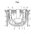
- the nuclear reactor vessel has been shown in the state it is in during the operation of the reactor.
- the tank is then filled with sodium to a level 7 and the core 8 of the reactor is completely immersed in liquid sodium.
- the main tank contains an internal tank 6 of complex shape providing inside the tank a zone 10 called hot collector containing the reactor core and in which the hot sodium having passed through the heart from bottom to top.
- Zone 11 of the main tank located outside the internal tank is called a cold collector and receives the cooled sodium leaving the intermediate heat exchangers 12 entering the tank through openings in the slab 2 and passing through the wall of the tank internal 6 thanks to a crossing device 14 whose sealing is ensured by pressurized gas.
- the internal tank 6 is generally constituted by two walls between which there remains a space filled with cold sodium at high pressure.
- Part of the cold sodium discharged by the pumps 15 circulates in contact with the internal wall of the main tank 1 for cooling.
- the main tank 1 is empty of sodium at the start of the preheating operation and contains all of its internal structures except for a pump 15 replaced by a device 20 for blowing hot gas which will be described in more detail below.
- this device 20 consists of two vertical coaxial tubular casings providing a central insufflation duct and an annular peripheral duct.
- the annular peripheral duct is closed at its lower part while the central duct opens into the bulb 15a of the pump in place of which the insufflation means 20 are arranged.
- a single pump 15 is replaced by an insufflation device 20, the other three pumps, in the case of a nuclear reactor comprising four pumps and eight heat exchangers, are placed in the tank before the start of preheating.
- the eight intermediate exchangers 12 are placed in their sealed passage chimney 14 connected to the internal tank 6.
- Nitrogen at high temperature is introduced into the intercuve space through six orifices 23 passing through the slab and opening into the upper part of this space.
- the nitrogen having circulated in the space between the tanks 1 and 3 is recovered by flexible tubes 21 of nitrogen extraction introduced into the space formed between the main tank 1 and the safety tank 3 by six through holes 25 the slab and opening into the intercuve space.
- the orifices 23 and 25 are arranged alternately on the periphery of the slab.
- Nitrogen can also be blown into the inteercuve space through openings distributed along the tube 21, the suction then taking place at the top by the tubes introduced through the orifices 23. In this configuration the circulation is reversed with respect to to the previous one.
- the nitrogen recovered by the tubes 21 (or 23) is sent to a heating installation.
- High temperature nitrogen is also blown through the device 20, into the bed base 17 supporting the core 8 of the reactor and into the cold manifold of the reactor. After circulation in contact with the internal structures of the reactor, the nitrogen is recovered by a tube 27 crossing the slab through the access hole of the fuel evacuation station and down dant substantially to the level of the assembly heads of the core.
- FIG. 5 we see such a heating installation which includes a battery of heaters 60 arranged in parallel.
- Each of the electrically heated heaters 60 is arranged on a branch of a heating circuit where the circulation of nitrogen is controlled by a set of valves.
- Each branch of the circuit includes a blower 61 for circulating the gas; on the upstream side, the branches are connected in parallel to a pipe 62 for recovering the heating gas from the inter-tank space and to a pipe 63 for recovering the heating gas from the interior of the main tank 1; on the downstream side, the branches are connected to a pipe 64 for transporting the heated gas to the inter-tank space and to a pipe 6 $ for transporting the heated gas to the internal space of the main tank.
- Valves 66 and 67 are arranged at the entrance to each of the branches on the conduits 62 and 63 respectively.
- valves 68 and 69 are arranged at the outlet of each of the branches on the pipes 64 and 65 respectively.
- conduits 62 and 64 are connected to the inter-tank space each by means of six tubes passing through the slab through the orifices 23 and 25 respectively.
- the lines 63 and 65 are connected to the tube 27 for recovering the gas in the hot manifold and by means of insufflation 20 respectively.
- Valves 70 and 71 allow the conduits 62 and 63 to be closed to the circulation of gas, respectively.
- Two pipes 73, 74 for exhaust to the atmosphere of the heated nitrogen provided with valves are also placed in bypass on the pipes 62 and 63 respectively.
- a nitrogen tank 75 is placed in bypass on line 62 for the initial supply of nitrogen to the circuit and to possibly compensate for leaks during use of the installation.
- the heating installation shown in FIG. 5 makes it possible to put into service, during the different phases of preheating, all or part of the branches of the circuit.
- the inlet and outlet valves of the branches make it possible to direct the nitrogen heated in the branches preferably in the inter-tank space or in the internal space of the main tank.
- the insufflation device 20 comprises an outer tube 31 whose diameter is substantially equivalent to the diameter of a pump secured to its upper part by a flange 32 which rests on the support 34 of the pump itself fixed on the slab 2, when the device 20 is in place in the tank.
- the orifice for the passage of the pump in the slab 2 is closed in leaktight manner by the flange 32.
- the outer tube 31 of the insufflation device 20 is connected at its upper part to a high temperature nitrogen inlet pipe. coming from the nitrogen heating station. Between this pipe and the tube 31 is interposed a butterfly valve 35 allowing the adjustment of the flow rate in the tube 31 and the closing of this tube 31 at its upper part.
- a butterfly valve 39 which allows the adjustment of the flow rate of the hot inert gas in the tube 37 and the closing of this tube at its upper part.
- Openings 40 and 41 are provided in the wall of the external tube 31 for the exit of the hot gas circulating in the peripheral annular space between the tubes 31 and 37, in the internal space of the tank. These openings 40 and 41 can be closed by flaps 40a and 4la respectively, the movement of which takes place in the annular space between the tubes 31 and 37 as shown in FIG. 6.
- FIG. 6 there is an opening 40 in the upper part of the device 20, at a level situated a little below the upper level of sodium when the tank is filled and two openings 41 located in the part bottom of the device 20 a little above the part of this device engaging in the bulb 15a of the pump.
- the opening 40 can be closed by a flap 40a secured to a rod 42 allowing it to be opened or closed and blocked in these positions.
- the two lower openings 41 can be closed by shutters 41a secured to a rod 43 allowing the shutters 41 to be opened and closed and locked in these positions.
- the vertical rods 42 and 43 are articulated on the inner surface of the tube 31 at their lower part and at their upper part and are integral with control devices for opening or closing the flaps at their upper end.
- FIGS. 3 and 4 describe the implementation of the method according to the invention using the device described with reference to FIGS. 6 and 7.
- One of the four pumps 15 of the nuclear reactor has been replaced by a gas blowing device as described with reference to FIGS. 6 and 7. All of the internal structures with the exception of this pump replaced by the device insufflation is in place in the tank. Preheating is prior to filling the tank with sodium.
- the hot gas path between the main tank 1 and the safety tank 3 has also been represented by arrows 51.
- FIG. 3 shows the path of the hot gas, which here is nitrogen at a temperature slightly above 140 ° C., inside the main tank 1 and in the inter-tank space, during a first phase of preheating where most of the hot gas is blown into the cold manifold of the internal tank.
- the lower windows 41 of the device 20 are open, the upper window 40 is closed and the valve 39 of the central duct 37 of the device 20 is partially closed.
- the outlets of the three pumps 15 which are not replaced by the insufflation device 20 opening into the cold manifold are closed.
- the valve opening setting is such that most of the hot gas enters the cold manifold through the windows 41. The rest of the hot gas is injected into the bed base 17 through the pump piping 18.
- the hot gas blown into the cold manifold leaves it to enter the hot manifold either by the pump pipes or by the exchangers, or by the sealing devices 14 of the exchangers. heat ers and for the very small part remaining by the flow space of the sodium for cooling the main tank.
- the hot gas blown into the bed base 17 for supporting the heart passes through the heart almost entirely to find itself in the hot collector. A very small part of this gas is blown into the deck and from there into the cooling sodium flow space of the main tank.
- All of the hot gas is found in the hot manifold and is extracted by the pipe 27 to return to the heating installation.
- the hot gas arriving through the orifices 23 is recovered by the tube 21 in the inter-tank space after having heated the external surface of the main tank 1.
- FIG. 4 shows the distribution of the hot gas flow rates in a second phase of the preheating where the gas is blown in roughly equal parts into the bed base and into the cold manifold of the reactor.
- a pump 15 is shown in solid lines at its location and in dotted lines at the same location, the device 20 replacing one of the four pumps 15 of the reactor.
- the windows 40 and 41 of the device 20 are all closed and consequently the hot gas is sent to the bulb 15a of the pump replaced by the insufflation device 20, the upper valves 35 and 39 of which are fully open. .
- the flow of hot gas therefore arrives both through the central space and the peripheral space in the bulb of the pump 15a so that the arrows 53 shown in dotted lines correspond to 100 X of the total flow.
- the hot gas is then sent to the bed base 17 of the reactor and part of this gas passes through the core of the reactor for its reheating to a temperature close to 140 ° C. A small part of this gas crosses the deck and heats the circulation spaces of the cooling sodium of the main tank.
- the rest of the heating gas passes through the conduits 18 of the three pumps which have not been replaced by the insufflation device 20 (arrows 54).
- the suction outlets 56 of these three pumps opening into the cold manifold are open so that the preheating gas entering through the pipes 18 in these pumps comes out in the cold manifold where it is distributed as before between the pump stacks, the exchangers and their chimneys, and the sodium return space for cooling the main tank.
- the whole of the main vessel of the reactor and its internal structures including the pumps and exchangers is at a temperature in the region of 140 °.
- valve 29 of the central tube 37 When the sodium arrives at the level of the bed base 17, the valve 29 of the central tube 37 is put in the closed position and the gas is no longer blown except through the windows 40 and 41 of the device 20, above the sodium.
- insufflation outside the internal tank, in the inter-tank space can be carried out constantly during the entire filling of the tank and that it is even possible to maintain this blowing for some time to maintain the tank and the sodium filling it at temperature, in concomittance with the heat input from the secondary circuit.
- This blowing from the outside of the tank can be adjusted with respect to the internal blowing of hot gas in contact with the internal structures.
- the invention is not limited to the embodiment which has just been described; on the contrary, it includes all variants. This is how one can imagine the use of several hot gas blowing devices arranged in place of reactor pumps. For example, it is possible to use two devices such as 20 replacing two pumps placed symmetrically with respect to the axis of the tank. Such an arrangement makes it possible to better balance the reheating by reducing the asymmetries during the circulation of the preheating gas.
- the invention applies not only in the case of a fast type neutron nuclear reactor of the integrated type but also in the case of fast type neutron nuclear reactors of the loop type.
- the process and the insufflation devices must be adapted to each case according to the structure of the tank and its internal components.
Landscapes
- Physics & Mathematics (AREA)
- Engineering & Computer Science (AREA)
- Plasma & Fusion (AREA)
- General Engineering & Computer Science (AREA)
- High Energy & Nuclear Physics (AREA)
- Filling Or Discharging Of Gas Storage Vessels (AREA)
- Heat-Exchange Devices With Radiators And Conduit Assemblies (AREA)
- Furnace Details (AREA)
- Monitoring And Testing Of Nuclear Reactors (AREA)
Applications Claiming Priority (2)
| Application Number | Priority Date | Filing Date | Title |
|---|---|---|---|
| FR8309733A FR2547448B1 (fr) | 1983-06-13 | 1983-06-13 | Procede de prechauffage d'une cuve et des structures internes d'un reacteur nucleaire a neutrons rapides refroidi par du metal liquide et moyens de prechauffage correspondants |
| FR8309733 | 1983-06-13 |
Publications (2)
| Publication Number | Publication Date |
|---|---|
| EP0129468A1 true EP0129468A1 (de) | 1984-12-27 |
| EP0129468B1 EP0129468B1 (de) | 1987-09-02 |
Family
ID=9289716
Family Applications (1)
| Application Number | Title | Priority Date | Filing Date |
|---|---|---|---|
| EP84401186A Expired EP0129468B1 (de) | 1983-06-13 | 1984-06-08 | Verfahren zum Vorwärmen eines Behälters und der inneren Bauteile eines mit flüssigem Metall gekühlten Kernreaktors mit schnellen Neutronen, sowie Vorwärmungseinrichtungen |
Country Status (4)
| Country | Link |
|---|---|
| EP (1) | EP0129468B1 (de) |
| JP (1) | JPS608794A (de) |
| DE (1) | DE3465813D1 (de) |
| FR (1) | FR2547448B1 (de) |
Cited By (1)
| Publication number | Priority date | Publication date | Assignee | Title |
|---|---|---|---|---|
| FR2684789A1 (fr) * | 1991-12-09 | 1993-06-11 | Doryokuro Kakunenryo | Reacteur nucleaire refroidi par metal liquide. |
Families Citing this family (1)
| Publication number | Priority date | Publication date | Assignee | Title |
|---|---|---|---|---|
| JPH068919B2 (ja) * | 1985-02-06 | 1994-02-02 | 株式会社日立製作所 | 原子炉構造予熱方法 |
Citations (5)
| Publication number | Priority date | Publication date | Assignee | Title |
|---|---|---|---|---|
| US3155595A (en) * | 1959-12-04 | 1964-11-03 | Babcock & Wilcox Co | Preheating and cooling a nuclear reactor system |
| FR2189821A1 (de) * | 1972-05-10 | 1974-01-25 | Westinghouse Electric Corp | |
| FR2365863A1 (fr) * | 1976-09-27 | 1978-04-21 | Westinghouse Electric Corp | Installation d'isolation et de prechauffage pour reacteur nucleaire |
| JPS5374694A (en) * | 1976-12-15 | 1978-07-03 | Power Reactor & Nuclear Fuel Dev Corp | Preheating method for liquid metal cooled type reactor |
| DE2734665A1 (de) * | 1977-08-01 | 1979-02-15 | Kraftwerk Union Ag | Vorrichtung zur verlaengerung der lebensdauer eines druckbehaelters, insbesondere eines reaktordruckbehaelters |
Family Cites Families (1)
| Publication number | Priority date | Publication date | Assignee | Title |
|---|---|---|---|---|
| JPS556255A (en) * | 1978-06-30 | 1980-01-17 | Tokyo Shibaura Electric Co | Nuclear reactor |
-
1983
- 1983-06-13 FR FR8309733A patent/FR2547448B1/fr not_active Expired
-
1984
- 1984-06-06 JP JP59116335A patent/JPS608794A/ja active Granted
- 1984-06-08 DE DE8484401186T patent/DE3465813D1/de not_active Expired
- 1984-06-08 EP EP84401186A patent/EP0129468B1/de not_active Expired
Patent Citations (5)
| Publication number | Priority date | Publication date | Assignee | Title |
|---|---|---|---|---|
| US3155595A (en) * | 1959-12-04 | 1964-11-03 | Babcock & Wilcox Co | Preheating and cooling a nuclear reactor system |
| FR2189821A1 (de) * | 1972-05-10 | 1974-01-25 | Westinghouse Electric Corp | |
| FR2365863A1 (fr) * | 1976-09-27 | 1978-04-21 | Westinghouse Electric Corp | Installation d'isolation et de prechauffage pour reacteur nucleaire |
| JPS5374694A (en) * | 1976-12-15 | 1978-07-03 | Power Reactor & Nuclear Fuel Dev Corp | Preheating method for liquid metal cooled type reactor |
| DE2734665A1 (de) * | 1977-08-01 | 1979-02-15 | Kraftwerk Union Ag | Vorrichtung zur verlaengerung der lebensdauer eines druckbehaelters, insbesondere eines reaktordruckbehaelters |
Cited By (1)
| Publication number | Priority date | Publication date | Assignee | Title |
|---|---|---|---|---|
| FR2684789A1 (fr) * | 1991-12-09 | 1993-06-11 | Doryokuro Kakunenryo | Reacteur nucleaire refroidi par metal liquide. |
Also Published As
| Publication number | Publication date |
|---|---|
| FR2547448A1 (fr) | 1984-12-14 |
| JPH0429039B2 (de) | 1992-05-15 |
| DE3465813D1 (en) | 1987-10-08 |
| FR2547448B1 (fr) | 1985-08-30 |
| JPS608794A (ja) | 1985-01-17 |
| EP0129468B1 (de) | 1987-09-02 |
Similar Documents
| Publication | Publication Date | Title |
|---|---|---|
| FR2635906A1 (fr) | Dispositif d'instrumentation du coeur d'un reacteur nucleaire a eau sous pression et procede et dispositif d'extraction et de mise en place de ce dispositif d'instrumentation | |
| EP0477066A1 (de) | Verfahren zum Austauschen eines Rohres eines Wärmetauschers und Anwendung dieses Verfahrens | |
| EP0129468B1 (de) | Verfahren zum Vorwärmen eines Behälters und der inneren Bauteile eines mit flüssigem Metall gekühlten Kernreaktors mit schnellen Neutronen, sowie Vorwärmungseinrichtungen | |
| EP0055963B1 (de) | Flüssigmetallgekühlter Kernreaktor mit einem am Boden gekühlten Behälter | |
| FR2535510A1 (fr) | Dispositif de purification du metal liquide de refroidissement d'un reacteur nucleaire a neutrons rapides | |
| EP0190075B1 (de) | Dampferzeuger mit flüssigem Metall als Wärmetransportmittel und mit Leckfeststellung durch Entnahme eines solchen flüssigen Metalles | |
| EP0258131B1 (de) | Notkühleinrichtung für schnellen Neutronenreaktor | |
| EP0144256B1 (de) | Anordnung zur thermischen Abschirmung einer Komponente eines Kernreaktors mit schnellen Neutronen | |
| EP0048672B1 (de) | Atomkernreaktor mit Wärmetauschern in integrierter Bauweise | |
| FR2721746A1 (fr) | Réacteur nucléaire à neutrons rapides de type intégré comportant des éléments de structure interne démontables. | |
| EP0064920B1 (de) | Vorrichtung zur Dampferzeugung und zur Ableitung von Wärme in einem schnellen Brüter | |
| EP0108690B1 (de) | Wärmetauscher für Fluide hoher Temperatur, wobei eines der Fluide an der Oberseite des Wärmetauschers ein- und austritt | |
| EP0018262A1 (de) | Schneller Kernreaktor mit einem zylindrischen Innenbehälter | |
| FR2665758A1 (fr) | Procede de bouchage d'un tube d'un echangeur de chaleur a tubes droits et utilisation de ce procede. | |
| WO2009083675A2 (fr) | Cuve reacteur d'un reacteur nucleaire a neutrons rapides de type a boucles | |
| FR2555794A1 (fr) | Reacteur nucleaire a neutrons rapides equipe de moyens de refroidissement de secours | |
| FR2505078A1 (fr) | Dispositif de refroidissement de la cuve principale d'un reacteur nucleaire a neutrons rapides | |
| EP0325879B1 (de) | Schneller Neutronenkernreaktor mit Zwischenwärmetauscher | |
| WO2014037363A1 (fr) | Reacteur nucleaire rapide integre, refroidi par un metal liquide, a echangeur intermediaire annulaire et moyens de surete passifs | |
| FR2750790A1 (fr) | Reacteur nucleaire comportant une cuve dans laquelle est dispose le coeur du reacteur et procede de refroidissement du coeur du reacteur a l'arret | |
| EP0184488B1 (de) | Integrierte Reinigungsvorrichtung für Flüssigmetallkühlmittel eines schnellen Neutronenreaktors | |
| FR2464539A1 (fr) | Ensemble de traversee de dalle de confinement pour transfert de combustible nucleaire irradie | |
| FR2542911A1 (fr) | Dispositif de purification integree du metal liquide de refroidissement d'un reacteur nucleaire a neutrons rapides | |
| EP0055969A1 (de) | Verfahren und Einrichtung zur Kühlung des Primärkreislaufs eines Druckwasserkernreaktors | |
| EP0090743A1 (de) | Schutzvorrichtung gegen Wärme und Radiation für einen in einem Kernreaktorbehälter eingetauchten Wärmeübertrager |
Legal Events
| Date | Code | Title | Description |
|---|---|---|---|
| PUAI | Public reference made under article 153(3) epc to a published international application that has entered the european phase |
Free format text: ORIGINAL CODE: 0009012 |
|
| AK | Designated contracting states |
Designated state(s): BE DE GB IT NL |
|
| 17P | Request for examination filed |
Effective date: 19841215 |
|
| 17Q | First examination report despatched |
Effective date: 19860120 |
|
| GRAA | (expected) grant |
Free format text: ORIGINAL CODE: 0009210 |
|
| AK | Designated contracting states |
Kind code of ref document: B1 Designated state(s): BE DE GB IT NL |
|
| ITF | It: translation for a ep patent filed | ||
| REF | Corresponds to: |
Ref document number: 3465813 Country of ref document: DE Date of ref document: 19871008 |
|
| GBT | Gb: translation of ep patent filed (gb section 77(6)(a)/1977) | ||
| PLBE | No opposition filed within time limit |
Free format text: ORIGINAL CODE: 0009261 |
|
| STAA | Information on the status of an ep patent application or granted ep patent |
Free format text: STATUS: NO OPPOSITION FILED WITHIN TIME LIMIT |
|
| 26N | No opposition filed | ||
| ITPR | It: changes in ownership of a european patent |
Owner name: FUSIONI;FRAMATOME |
|
| NLS | Nl: assignments of ep-patents |
Owner name: FRAMATOME TE COURBEVOIE, FRANKRIJK. |
|
| PGFP | Annual fee paid to national office [announced via postgrant information from national office to epo] |
Ref country code: GB Payment date: 19910531 Year of fee payment: 8 |
|
| PGFP | Annual fee paid to national office [announced via postgrant information from national office to epo] |
Ref country code: DE Payment date: 19910603 Year of fee payment: 8 |
|
| PGFP | Annual fee paid to national office [announced via postgrant information from national office to epo] |
Ref country code: BE Payment date: 19910626 Year of fee payment: 8 |
|
| ITTA | It: last paid annual fee | ||
| REG | Reference to a national code |
Ref country code: GB Ref legal event code: 732 |
|
| PG25 | Lapsed in a contracting state [announced via postgrant information from national office to epo] |
Ref country code: GB Effective date: 19920608 |
|
| PG25 | Lapsed in a contracting state [announced via postgrant information from national office to epo] |
Ref country code: BE Effective date: 19920630 |
|
| PGFP | Annual fee paid to national office [announced via postgrant information from national office to epo] |
Ref country code: NL Payment date: 19920630 Year of fee payment: 9 |
|
| BERE | Be: lapsed |
Owner name: FRAMATOME Effective date: 19920630 |
|
| PG25 | Lapsed in a contracting state [announced via postgrant information from national office to epo] |
Ref country code: NL Effective date: 19930101 |
|
| GBPC | Gb: european patent ceased through non-payment of renewal fee |
Effective date: 19920608 |
|
| NLV4 | Nl: lapsed or anulled due to non-payment of the annual fee | ||
| PG25 | Lapsed in a contracting state [announced via postgrant information from national office to epo] |
Ref country code: DE Effective date: 19930302 |