EP0129187B1 - Protecting device against the running dry of a diaphragm piston pump - Google Patents
Protecting device against the running dry of a diaphragm piston pump Download PDFInfo
- Publication number
- EP0129187B1 EP0129187B1 EP84106687A EP84106687A EP0129187B1 EP 0129187 B1 EP0129187 B1 EP 0129187B1 EP 84106687 A EP84106687 A EP 84106687A EP 84106687 A EP84106687 A EP 84106687A EP 0129187 B1 EP0129187 B1 EP 0129187B1
- Authority
- EP
- European Patent Office
- Prior art keywords
- sensor
- pump
- level
- warning
- measurement
- Prior art date
- Legal status (The legal status is an assumption and is not a legal conclusion. Google has not performed a legal analysis and makes no representation as to the accuracy of the status listed.)
- Expired
Links
Images

Classifications
-
- F—MECHANICAL ENGINEERING; LIGHTING; HEATING; WEAPONS; BLASTING
- F04—POSITIVE - DISPLACEMENT MACHINES FOR LIQUIDS; PUMPS FOR LIQUIDS OR ELASTIC FLUIDS
- F04B—POSITIVE-DISPLACEMENT MACHINES FOR LIQUIDS; PUMPS
- F04B23/00—Pumping installations or systems
- F04B23/04—Combinations of two or more pumps
- F04B23/06—Combinations of two or more pumps the pumps being all of reciprocating positive-displacement type
-
- F—MECHANICAL ENGINEERING; LIGHTING; HEATING; WEAPONS; BLASTING
- F04—POSITIVE - DISPLACEMENT MACHINES FOR LIQUIDS; PUMPS FOR LIQUIDS OR ELASTIC FLUIDS
- F04B—POSITIVE-DISPLACEMENT MACHINES FOR LIQUIDS; PUMPS
- F04B49/00—Control, e.g. of pump delivery, or pump pressure of, or safety measures for, machines, pumps, or pumping installations, not otherwise provided for, or of interest apart from, groups F04B1/00 - F04B47/00
- F04B49/10—Other safety measures
Definitions
- the invention relates to a dry-running protection device for the metering piston of a piston diaphragm pump designed for conveying liquid media.
- Such a protective device to avoid the dry running of the metering piston and thus possible damage to the sealing elements and thus also overloading of the electrical or pneumatic pump drive is necessary in a large number of pumps designed to convey liquid media.
- the signal from this protective device is generally used to switch off the pump motor and / or to signal the acoustic or optical product empty warning.
- the protective devices are designed as electrical or thermal overload safeguards when using an electric drive motor. Such protective devices are limited to use with electrical drives. Another disadvantage is that the fuses only respond when mechanical damage to the sealing elements and thus stiffness has usually occurred.
- Another protective device is designed as a pressure switch with a throttle or pressure maintaining valve in the metering line.
- a control body monitors whether the product is being conveyed when the drive energy is applied and whether pressure is being built up. However, in this case, too, an interference signal is only emitted when the set metering quantity is no longer reached or no metering is carried out at all.
- the invention has for its object to provide a protective device that issues a warning signal and / or the pump independently of the drive energy, before the drop or failure of the metering performance due to product shortage and without the connection of disruptive external electrical lines from the product supply container to the metering pump switches off automatically in the event of danger.
- the solution is characterized by at least one measuring sensor integrated in the pump head body in the area of the pre-delivery chamber above a minimum liquid level which just just covers the metering piston, with downstream empty warning and / or pump shutdown means . Improvements and further refinements are described in the subclaims.
- one, two or three sensors should be attached in the pump head body in the area of the pre-delivery chamber, depending on the type of pumped medium and depending on the desired shutdown signal, so that when the liquid level slowly drops in the pre-delivery chamber, one or more signals are emitted which are transmitted via corresponding, e.g. electronic translation elements for visual or acoustic product empty warning and / or safety shutdown of the pump are to be used.
- the dosing time remaining from a product empty pre-warning until the dosing plunger emerges and thus the pump runs dry can be specified differently depending on the design of the volume ratio between the pre-delivery chamber and dosing plunger and depending on the stroke set.
- electrically conductive carbon or metal pins are sufficient as measuring sensors, i.e. as measuring electrodes.
- an additional sensor can be arranged as a reference sensor in the lower region of the pumped medium below the lowest level of the metering piston.
- a sensor for product empty warning i.e. a prewarning sensor and a sensor for safety shutdown of the pump, i.e. a switch-off sensor can be provided.
- a certain electrical resistance is measured and reported to an electronic transmission element via the respective measuring lines.
- the downstream warning device is put into operation - via an electronic translation element or the like.
- the prewarning sensor is, by definition, placed far above the level dangerous for the dosing piston to run dry, the dosing piston is still fully within the medium during the prewarning, and at this time the sealing elements of the dosing piston are not damaged.
- the level of the switch-off sensor is finally reached. If the liquid level falls below this level, the cut-off sensor gives a signal to the downstream cut-off means and the pump or the pump drive is stopped. It is then not possible for the metering piston to emerge and run dry, and thus damage to the sealing elements or even blockage of the pump.
- the product empty warning and safety shutdown can be provided or prepared individually or at the same time, depending on the requirements.
- a pump to be protected according to the invention is used to convey non-conductive liquids
- the reference sensor inserted into the liquid which is clearly below the lowest level of the metering pump, is generally not required.
- a prewarning sensor and / or a switch-off sensor can, however, be provided in the same way as for operation with electrically conductive liquid and can be switched to prewarning or switch-off means.
- the prewarning sensors or switch-off sensors are preferably used as semiconductor components, eg. designed as PTC or NTO elements.
- the level drops below the level to be measured when using PTC sensors, so that the corresponding sensor dips and is no longer cooled by the fluid, it heats up to its switching point (PTC 60 e.g. 60 ° C) and gives a signal to a downstream, eg electronic translation link.
- PTC 60 e.g. 60 ° C
- NTC elements the reverse is done.
- the measuring line consists of two strands for each measuring point, since the outgoing and return lines must be run separately for each measuring point. Even when measuring in non-conductive media, you can work with one or two measuring points.
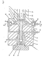
- the piston-diaphragm pump consists of a pump head body 1 with pre-feed chamber 2, the metering piston 6 with sealing elements 7 and the metering piston 6 opposite pressure maintaining valve with stroke adjusting screw 15, spring 16 and ball 17 and sealing element 8 for the ball 17.
- the metering piston 6 is via a Drive piston 21 mounted in a slide bearing 20 is actuated, the conveying medium 12 being introduced to the metering piston 6 with the aid of a pre-delivery membrane 13 fastened in the pump head receptacle 14.
- the pre-delivery chamber 2 is assigned a suction valve 18 with a ball and seal, via which the delivery medium 12 can be drawn into the pump in the direction of arrow 22.
- the pre-delivery chamber also has a return valve 19 with ball and seal, from which the delivery medium 12 is to be expelled in the direction of arrow 23.
- the metering takes place on the back of the pressure control valve in the direction of arrow 24.
- the pump according to FIGS. 1 and 2 contains an upper measuring sensor or pre-warning sensor 3, a middle measuring sensor or shut-off sensor 4 and a lower measuring sensor or reference sensor 5 in the pre-delivery chamber 2 located in the pump head body 1.
- the pre-warning sensor 3 is at a level 111 within the measuring liquid or the conveying medium 12 far above the metering piston 6 or of its sealing elements 7 or sealing elements 8 of the pressure control valve.
- the switch-off sensor 4 is at a level IV, which the medium 12 must not fall below if the metering piston 6 and the seals 7 and 8 are not to be in danger.
- the conveying medium 12 is electrically conductive and the sensors 3 to 5 are electrical measuring electrodes, to which measuring lines 9 to 10 are connected downstream to an electronic translation element (not shown).
Abstract
Description
Die Erfindung betrifft eine Trockenlauf-Schutzvorrichtung für den Dosierkolben einer zum Fördern flüssiger Medien ausgelegten Kolben-Membranpumpe.The invention relates to a dry-running protection device for the metering piston of a piston diaphragm pump designed for conveying liquid media.
Eine solche Schutzvorrichtung zum Vermeiden des Trockenlaufs des Dosierkolbens und somit einer möglichen Beschädigung der Dichtungselemente sowie damit auch Überlastung des elektrischen oder pneumatischen Pumpenantriebs ist bei einer Vielzahl zum Fördern flüssiger Medien ausgelegter Pumpen erforderlich. Das Signal dieser Schutzvorrichtung wird in der Regel zum Abschalten das Pumpenmotors und/oder zur akustischen bzw. optischen Produkt-Leermeldevorwarnung verwendet.Such a protective device to avoid the dry running of the metering piston and thus possible damage to the sealing elements and thus also overloading of the electrical or pneumatic pump drive is necessary in a large number of pumps designed to convey liquid media. The signal from this protective device is generally used to switch off the pump motor and / or to signal the acoustic or optical product empty warning.
Zum großen Teil werden die Schutzvorrichtungen als elektrische oder thermische Überlastsicherungen bei Verwendung eines elektrischen Antriebsmotors ausgeführt. Solche Schutzvorrichtungen sind auf den Eingatz bei elektrischen Antrieben beschränkt. Ein weiterer Nachteil besteht darin, daß die Sicherungen erst ansprechen, wenn meist schon eine mechanische Beschädigung der Dichtungselemente und somit eine Schwergängigkeit eingetreten ist.For the most part, the protective devices are designed as electrical or thermal overload safeguards when using an electric drive motor. Such protective devices are limited to use with electrical drives. Another disadvantage is that the fuses only respond when mechanical damage to the sealing elements and thus stiffness has usually occurred.
Eine andere Schutzvorrichtung ist als Druckschalter mit Drossel- oder Druckhalteventil in der Dosierleitung ausgebildet. Durch ein Kontrollorgan wird hierbei überwacht, ob bei Anlegen der Antriebsenergie Produkt gefördert und somit Druck aufgebaut wird. Jedoch wird auch in diesem Fall ein Störsignal erst dann abgegeben, wenn die eingestellte Dosiermenge nicht mehr erreicht wird oder gar keine Dosierung mehr erfolgt.Another protective device is designed as a pressure switch with a throttle or pressure maintaining valve in the metering line. A control body monitors whether the product is being conveyed when the drive energy is applied and whether pressure is being built up. However, in this case, too, an interference signal is only emitted when the set metering quantity is no longer reached or no metering is carried out at all.
Wieder weitere Schutzvorrichtungen, die mit externer Produkt-Leermeldevorwarnung bzw. mit einem in das Produktvorratsgebinde einzusetzenden Niveautaster arbeiten, benötigen eine externe elektrische Verkabelung, die bei großen Entfernungen zwischen Pumpe und Produktvorratsgebinde nachteilig ist. Der Erfindung liegt die Aufgabe zugrunde, eine Schutzvorrichtung zu schaffen, die unabhängig von der Antriebsenergie, zeitlich vor Abfall bzw. Ausfall der Dosierleistung auf Grund von Produktmangel und ohne die Verbindung störender externer elektrischer Zuleitungen vom Produktvorratsgebinde zur Dosierpumpe ein Vorwarnsignal abgibt und/ oder die Pumpe bei Gefahr automatisch abschaltet. Für die Trockenlauf-Schutzvorrichtung für den Dosierkolben einer Kolben-Membranpumpe eingangs genannter Art ist die Lösung gekennzeichnet durch mindestens einen in den Pumpenkopfkörper im Bereich der Vorförderkammer oberhalb eines den Dosierkolben noch gerade ganz bedeckenden Flüssigkeits-Minimalniveaus integrierten Meßfühler mit nachgeschalteten Leermeldevorwarn- und/oder Pumpenabschaltmitteln. Verbesserungen und weitere Ausgestaltungen werden in den Unteransprüchen beschrieben.Further protective devices that work with external product empty warning or with a level sensor to be inserted into the product supply container require external electrical wiring, which is disadvantageous in the case of large distances between the pump and the product supply container. The invention has for its object to provide a protective device that issues a warning signal and / or the pump independently of the drive energy, before the drop or failure of the metering performance due to product shortage and without the connection of disruptive external electrical lines from the product supply container to the metering pump switches off automatically in the event of danger. For the dry-running protection device for the metering piston of a piston diaphragm pump of the type mentioned at the outset, the solution is characterized by at least one measuring sensor integrated in the pump head body in the area of the pre-delivery chamber above a minimum liquid level which just just covers the metering piston, with downstream empty warning and / or pump shutdown means . Improvements and further refinements are described in the subclaims.
Erfindungsgemäß sollen im Pumpenkopfkörper im Bereich der Vorförderkammer je nach Art des Fördermediums und je nach gewünschtem Abschaltsignal ein, zwei oder drei Meßfühler wahlweise so angebracht werden, daß bei langsamem Absinken des Flüssigkeitsniveaus in der Vorförderkammer ein oder mehrere Signale abgegeben werden, die über entsprechende, z.B. elektronische Übersetzungsglieder zur optischen oder akustischen Produkt-Leermeidevorwarnung und/oder Sicherheitsabschaltung der Pumpe heranzuziehen sind. Die von einer Produkt-Leermeldevorwarnung bis zum Austauchen des Dosierkolbens und somit zum Trockenlauf der Pumpe verbleibende Dosierzeit kann je nach Auslegung des Volumenverhältnisses zwischen Vorförderkammer und Dosierkolben und je nach dem eingestellten Hub verschieden vorgegeben werden.According to the invention, one, two or three sensors should be attached in the pump head body in the area of the pre-delivery chamber, depending on the type of pumped medium and depending on the desired shutdown signal, so that when the liquid level slowly drops in the pre-delivery chamber, one or more signals are emitted which are transmitted via corresponding, e.g. electronic translation elements for visual or acoustic product empty warning and / or safety shutdown of the pump are to be used. The dosing time remaining from a product empty pre-warning until the dosing plunger emerges and thus the pump runs dry can be specified differently depending on the design of the volume ratio between the pre-delivery chamber and dosing plunger and depending on the stroke set.
Bei leitfähigen zu fördernden Flüssigkeiten genügen elektrisch leitende Kohle- oder Metallstifte als Meßfühler, d.h. als Meßelektroden. In diesem Falle kann ein zusätzlicher Meßfühler als Bezugsmeßfühler im unteren Bereich des Fördermediums unterhalb des untersten Niveaus des Dosierkolbens angeordnet werden. Ferner können ein Meßfühler zur Produkt-Leermeldevorwarnung, d.h. ein Vorwamfühler, und ein Meßfühler zur Sicherheitsabschaltung der Pumpe, d.h. ein Abschaltfühler, vorgesehen werden. Wenn in diesem Fall die Vorförderkammer ausreichend mit Flüssigkeit gefüllt ist und zwischen den drei Meßfühlern, nämlich dem Bezugsfühler, dem Vorwarnfühler und dem Abschaltfühler, leitfähiges Fördermedium anliegt, wird ein gewisser elektrischer Widerstand gemessen und über die jeweiligen Meßleitungen an ein elektronisches Ubersetzungsglied gemeldet. Sinkt jedoch das Niveau des Fördermediums unter das Niveau des Vorwarnfühlers ab, so daß keine leitfähige Verbindung zwischen den Meßfühlern mehr besteht, so steigt der elektrische Widerstand gegen unendlich an. Dadurch wird das nachgeschaltete Vorwarnmittel - über ein elektronisches Übersetzungsglied oder dergleichen - in Betrieb gesetzt. Da jedoch der Vorwarnfühler definitionsgemäß weit über dem für das Trockenlaufen des Dosierkolbens gefährlichen Niveau angebracht wird, befindet sich der Dosierkolben während der Vorwarnung immer noch voll innerhalb des Fördermediums, und zu dieser Zeit tritt eine Schädigung der Dichtelemente des Dosierkolbens noch nicht ein.For conductive liquids to be pumped, electrically conductive carbon or metal pins are sufficient as measuring sensors, i.e. as measuring electrodes. In this case, an additional sensor can be arranged as a reference sensor in the lower region of the pumped medium below the lowest level of the metering piston. Furthermore, a sensor for product empty warning, i.e. a prewarning sensor and a sensor for safety shutdown of the pump, i.e. a switch-off sensor can be provided. In this case, if the pre-delivery chamber is sufficiently filled with liquid and there is a conductive medium between the three sensors, namely the reference sensor, the pre-warning sensor and the shut-off sensor, a certain electrical resistance is measured and reported to an electronic transmission element via the respective measuring lines. However, if the level of the pumped medium drops below the level of the pre-warning sensor, so that there is no longer a conductive connection between the sensors, the electrical resistance increases to infinity. As a result, the downstream warning device is put into operation - via an electronic translation element or the like. However, since the prewarning sensor is, by definition, placed far above the level dangerous for the dosing piston to run dry, the dosing piston is still fully within the medium during the prewarning, and at this time the sealing elements of the dosing piston are not damaged.
Wird jedoch die Produkt-Leermeldevorwarnung nicht beachtet und das Niveau in der Vorförderkammer sinkt weiter ab, so wird schließlich das Niveau des Abschaltfühlers erreicht. Wenn das Flüssigkeitsniveau unterhalb dieses Niveau fällt, gibt der Abschaltfühler ein Signal an die nachgeschalteten Abschaltmittel, und die Pumpe bzw. der Pumpenantrieb wird stillgesetzt. Es kann dann also ein Austauchen und Trockenlaufen des Dosierkolbens und damit eine Schädigung der Dichtelemente bzw. sogar ein Blockieren der Pumpe nicht eintreten.However, if the product empty warning warning is ignored and the level in the pre-feed chamber continues to drop, the level of the switch-off sensor is finally reached. If the liquid level falls below this level, the cut-off sensor gives a signal to the downstream cut-off means and the pump or the pump drive is stopped. It is then not possible for the metering piston to emerge and run dry, and thus damage to the sealing elements or even blockage of the pump.
Die Produkt-Leermeldevorwarnung und Sicherheitsabschaltung kann je nach Erfordernis einzeln oder zugleich vorgesehen bzw. vorbereitet werden.The product empty warning and safety shutdown can be provided or prepared individually or at the same time, depending on the requirements.
Wenn eine erfindungsgemäß zu schützende Pumpe zum Fördern nicht leitfähiger Flüssigkeiten eingesetzt wird, entfällt in der Regel der deutlich unterhalb des untersten Niveaus der Dosierpumpe in die Flüssigkeit eingesetzte Bezugsfühler. Ein Vorwarnfühler und/oder ein Abschaltfühler können jedoch in gleicher Weise wie bei dem Betrieb mit elektrisch leitfähiger Flüssigkeit vorgesehen und auf Vorwarn- bzw. Abschaltmittel geschaltet werden. Vorzugsweise werden die Vorwarnnfühler bzw. Abschaltfühler in solchen Fällen als Halbleiterbauelemente, z,B. als PTC-oder NTO-Elemente ausgebildet.If a pump to be protected according to the invention is used to convey non-conductive liquids, the reference sensor inserted into the liquid, which is clearly below the lowest level of the metering pump, is generally not required. A prewarning sensor and / or a switch-off sensor can, however, be provided in the same way as for operation with electrically conductive liquid and can be switched to prewarning or switch-off means. In such cases, the prewarning sensors or switch-off sensors are preferably used as semiconductor components, eg. designed as PTC or NTO elements.
Sinkt bei Einsatz von PTC-Meßfühlern das Niveau unterhalb des jeweils zu erfassenden Pegels ab, so daß der entsprechende Meßfühler austaucht und nicht mehr vom Fördermedium gekühlt wird, so heizt er sich bis zu seinem Schaltpunkt (PTC 60 z.B. 60° C) auf und gibt über eine entsprechende Meßleitung ein Signal an ein nachgeschaltetes, z.B. elektronisches Übersetzungsglied ab. Bei NTC-Elementen wird genau umgekehrt geschaltet. Die Meßleitung besteht in diesen Fällen für jeden Meßpunkt aus jeweils zwei Litzen, da die Hin- und Rückleitung hierfür jeden Meßpunkt separat zu führen ist. Auch bei der Messung in nicht leitfähigen Fördermedien kann sowohl mit einem als auch mit zwei Meßpunkten gearbeitet werden.If the level drops below the level to be measured when using PTC sensors, so that the corresponding sensor dips and is no longer cooled by the fluid, it heats up to its switching point (PTC 60 e.g. 60 ° C) and gives a signal to a downstream, eg electronic translation link. In the case of NTC elements, the reverse is done. In these cases, the measuring line consists of two strands for each measuring point, since the outgoing and return lines must be run separately for each measuring point. Even when measuring in non-conductive media, you can work with one or two measuring points.
Anhand der schematischen Darstellung eines Ausführungsbeispiels werden Einzelheiten der Erfindung erläutert. Es zeigen:
- Fig. 1 einen Längsschnitt durch eine Kolben-Membranpumpe; und
- Fig. 2 einen Schnitt längs der Linie 11-11 von Fig. 1.
- 1 shows a longitudinal section through a piston diaphragm pump. and
- 2 shows a section along the line 11-11 of FIG. 1st
Die Kolben-Membranpumpe gemäß Ausführungsbeispiel besteht aus einem Pumpenkopfkörper 1 mit Vorförderkammer 2, dem Dosierkolben 6 mit Dichtungselementen 7 und dem Dosierkolben 6 gegenüberstehendem Druckhalteventil mit Hubeinstellschraube 15, Feder 16 und Kugel 17 sowie Dichtungselement 8 für die Kugel 17. Der Dosierkolben 6 wird über einen in einem Gleitlager 20 gelagerten Antriebskolben 21 betätigt, wobei das Fördermedium 12 dem Dosierkolben 6 mit Hilfe einer in der Pumpenkopfaufnahme 14 befestigten Vorfördermembrane 13 vorgelegt wird. Der Vorförderkammer 2 wird ein Saugventil 18 mit Kugel und Dichtung zugeordnet, über das das Fördermedium 12 in Pfeilrichtung 22 in die Pumpe einzusaugen ist. Die Vorförderkammer besitzt ferner ein Rücklaufventil 19 mit Kugel und Dichtung, aus der das Fördermedium 12 in Pfeilrichtung 23 auszutreiben ist. Die Dosierung erfolgt auf der Rückseite des Druckhalteventils in Pfeilrichung 24.The piston-diaphragm pump according to the exemplary embodiment consists of a pump head body 1 with
Die Pumpe nach Fig. 1 und 2 enthält in der im Pumpenkopfkörper 1 befindlichen Vorförderkammer 2 einen oberen Meßfühler bzw. Vorwarnfühler 3, einen mittleren Meßfühler bzw. Abschaltfühler 4 und einen unteren Meßfühler bzw. Bezugsfühler 5. Der Vorwarnfühler 3 befindet sich in einem Pegelniveau 111 innerhalb der Meßflüssigkeit bzw. des Fördermediums 12 weit oberhalb des Dosierkolbens 6 bzw. von dessen Dichtungselementen 7 oder Dichtungselementen 8 des Druckhalteventils. Demgegenüber befindet sich der Abschaltfühler 4 auf einem Pegelniveau IV, das von dem Fördermedium 12 keinesfalls unterschritten werden darf, wenn nicht der Dosierkolben 6 sowie die Dichtungen 7 und 8 in Gefahr kommen sollen.The pump according to FIGS. 1 and 2 contains an upper measuring sensor or pre-warning
Im Ausführungsbeispiel wird angenommen, das Fördermedium 12 sei elektrisch leitend und die Meßfühler 3 bis 5 seien elektrische Meßelektroden, denen Meßleitungen 9 bis 10 zu einem nicht gezeichneten elektronischen Übersetzungsglied nachgeschaltet werden.In the exemplary embodiment it is assumed that the

Claims (8)
Priority Applications (1)
| Application Number | Priority Date | Filing Date | Title |
|---|---|---|---|
| AT84106687T ATE22484T1 (en) | 1983-06-18 | 1984-06-12 | DRY RUNNING PROTECTION DEVICE OF A PISTON DIAPHRAGM PUMP. |
Applications Claiming Priority (2)
| Application Number | Priority Date | Filing Date | Title |
|---|---|---|---|
| DE3321959 | 1983-06-18 | ||
| DE3321959A DE3321959A1 (en) | 1983-06-18 | 1983-06-18 | DRY RUN PROTECTION OF A PISTON DIAPHRAGM PUMP |
Publications (3)
| Publication Number | Publication Date |
|---|---|
| EP0129187A2 EP0129187A2 (en) | 1984-12-27 |
| EP0129187A3 EP0129187A3 (en) | 1985-04-10 |
| EP0129187B1 true EP0129187B1 (en) | 1986-09-24 |
Family
ID=6201751
Family Applications (1)
| Application Number | Title | Priority Date | Filing Date |
|---|---|---|---|
| EP84106687A Expired EP0129187B1 (en) | 1983-06-18 | 1984-06-12 | Protecting device against the running dry of a diaphragm piston pump |
Country Status (3)
| Country | Link |
|---|---|
| EP (1) | EP0129187B1 (en) |
| AT (1) | ATE22484T1 (en) |
| DE (2) | DE3321959A1 (en) |
Cited By (1)
| Publication number | Priority date | Publication date | Assignee | Title |
|---|---|---|---|---|
| EP1510698A2 (en) | 2003-08-26 | 2005-03-02 | Herborner Pumpenfabrik J.H.Hoffmann GmbH & Co. | Device for protecting a pump against dry running |
Families Citing this family (1)
| Publication number | Priority date | Publication date | Assignee | Title |
|---|---|---|---|---|
| DE29708906U1 (en) | 1997-05-21 | 1997-07-17 | Lang Apparatebau Gmbh | Piston diaphragm pump with sealless piston-cylinder unit |
Family Cites Families (3)
| Publication number | Priority date | Publication date | Assignee | Title |
|---|---|---|---|---|
| CH498297A (en) * | 1969-05-06 | 1970-10-31 | Jacques Tobler Ag | Method and device for monitoring the function of a metering pump and the storage supply of the liquid to be metered |
| US3862571A (en) * | 1973-08-06 | 1975-01-28 | Agridustrial Electronics | Multielectrode capacitive liquid level sensing system |
| DE2651614C2 (en) * | 1976-11-12 | 1984-10-04 | Lang Apparatebau GmbH, 8227 Siegsdorf | Dosing pump |
-
1983
- 1983-06-18 DE DE3321959A patent/DE3321959A1/en not_active Withdrawn
-
1984
- 1984-06-12 EP EP84106687A patent/EP0129187B1/en not_active Expired
- 1984-06-12 AT AT84106687T patent/ATE22484T1/en not_active IP Right Cessation
- 1984-06-12 DE DE8484106687T patent/DE3460814D1/en not_active Expired
Cited By (1)
| Publication number | Priority date | Publication date | Assignee | Title |
|---|---|---|---|---|
| EP1510698A2 (en) | 2003-08-26 | 2005-03-02 | Herborner Pumpenfabrik J.H.Hoffmann GmbH & Co. | Device for protecting a pump against dry running |
Also Published As
| Publication number | Publication date |
|---|---|
| EP0129187A2 (en) | 1984-12-27 |
| EP0129187A3 (en) | 1985-04-10 |
| DE3321959A1 (en) | 1984-12-20 |
| ATE22484T1 (en) | 1986-10-15 |
| DE3460814D1 (en) | 1986-10-30 |
Similar Documents
| Publication | Publication Date | Title |
|---|---|---|
| WO1999049206A2 (en) | Flange for fuel delivery module and fuel delivery module | |
| DE3509225A1 (en) | ONE-PIECE OIL PRESSURE MEASURING DEVICE | |
| EP0129187B1 (en) | Protecting device against the running dry of a diaphragm piston pump | |
| DE2125809A1 (en) | Pressostat | |
| DE10224142A1 (en) | Inline flow switch using magnetic forces | |
| EP0425866A2 (en) | Process and apparatus to bring small quantities of a paste on a circuit board | |
| DE19848234A1 (en) | Compression of potentially explosive gases through injection of liquid into a common vessel | |
| DE4027027C2 (en) | Method for detecting a break in a membrane and membrane conveyor unit | |
| DE8317712U1 (en) | DRY RUN PROTECTION OF A PISTON DIAPHRAGM PUMP | |
| EP1041595A2 (en) | Centrifugal pump unit | |
| EP0499347B1 (en) | Central lubricating unit | |
| DE102007014450B3 (en) | Retaining device for bulk materials i.e. fuel pellets, has filling-level meter i.e. capacitive sensor, arranged close to emptying opening and connected with electrical circuit of controller, and pressure sensor integrated in pressure line | |
| DE2847431A1 (en) | DOSING DEVICE | |
| DE2826271A1 (en) | ARRANGEMENT FOR MOUNTING ELECTRICAL OR ELECTRONIC DEVICES IN DEVICES FOR DISPENSING FUEL OR FUEL | |
| EP0126708A2 (en) | Device for checking the functioning of a central lubrication system | |
| DE2934301A1 (en) | DEVICE FOR CHARGING PRESSURE STORAGE WITH HIGH-COMPRESSED GAS IN HYDRAULIC SYSTEMS. | |
| DE2513846A1 (en) | CONTROL DEVICE FOR OIL PRESSURE ACCUMULATOR | |
| DE3209845A1 (en) | Liquid-delivery device with a sensor | |
| DE3829291C1 (en) | Apparatus for producing a reaction mixture for forming multi-component plastics, in particular polyurethane | |
| EP0370136B1 (en) | Lubricant supply device | |
| DD260548A1 (en) | DEVICE FOR PREVENTING THE DRY RUN OF PUMPS | |
| DE2032715A1 (en) | Suspension strut with automatic level control | |
| DE3201588A1 (en) | Safety device for containers and conveying systems | |
| DE3921231A1 (en) | Flow monitor, e.g. for buffer soln. in high pressure - LC has chamber with inlet, outlet and contact electrode arrangement | |
| DE8408789U1 (en) | OSCILLATING DISPLACEMENT PUMP |
Legal Events
| Date | Code | Title | Description |
|---|---|---|---|
| PUAI | Public reference made under article 153(3) epc to a published international application that has entered the european phase |
Free format text: ORIGINAL CODE: 0009012 |
|
| AK | Designated contracting states |
Designated state(s): AT CH DE FR IT LI |
|
| PUAL | Search report despatched |
Free format text: ORIGINAL CODE: 0009013 |
|
| AK | Designated contracting states |
Designated state(s): AT CH DE FR IT LI |
|
| 17P | Request for examination filed |
Effective date: 19850424 |
|
| RTI1 | Title (correction) | ||
| GRAA | (expected) grant |
Free format text: ORIGINAL CODE: 0009210 |
|
| AK | Designated contracting states |
Kind code of ref document: B1 Designated state(s): AT CH DE FR IT LI |
|
| REF | Corresponds to: |
Ref document number: 22484 Country of ref document: AT Date of ref document: 19861015 Kind code of ref document: T |
|
| REF | Corresponds to: |
Ref document number: 3460814 Country of ref document: DE Date of ref document: 19861030 |
|
| ITF | It: translation for a ep patent filed |
Owner name: STUDIO JAUMANN |
|
| ET | Fr: translation filed | ||
| PLBE | No opposition filed within time limit |
Free format text: ORIGINAL CODE: 0009261 |
|
| STAA | Information on the status of an ep patent application or granted ep patent |
Free format text: STATUS: NO OPPOSITION FILED WITHIN TIME LIMIT |
|
| 26N | No opposition filed | ||
| PG25 | Lapsed in a contracting state [announced via postgrant information from national office to epo] |
Ref country code: AT Effective date: 19880612 |
|
| PG25 | Lapsed in a contracting state [announced via postgrant information from national office to epo] |
Ref country code: LI Effective date: 19880630 Ref country code: CH Effective date: 19880630 |
|
| PG25 | Lapsed in a contracting state [announced via postgrant information from national office to epo] |
Ref country code: FR Free format text: LAPSE BECAUSE OF NON-PAYMENT OF DUE FEES Effective date: 19890228 |
|
| REG | Reference to a national code |
Ref country code: CH Ref legal event code: PL |
|
| REG | Reference to a national code |
Ref country code: FR Ref legal event code: ST |
|
| PGFP | Annual fee paid to national office [announced via postgrant information from national office to epo] |
Ref country code: DE Payment date: 19890524 Year of fee payment: 6 |
|
| PG25 | Lapsed in a contracting state [announced via postgrant information from national office to epo] |
Ref country code: DE Effective date: 19910301 |