EP0128912B1 - Hydraulische, pneumatische, pneumatische/hydraulische oder kombinierte pneumatische/explosionspresse - Google Patents
Hydraulische, pneumatische, pneumatische/hydraulische oder kombinierte pneumatische/explosionspresse Download PDFInfo
- Publication number
- EP0128912B1 EP0128912B1 EP84900019A EP84900019A EP0128912B1 EP 0128912 B1 EP0128912 B1 EP 0128912B1 EP 84900019 A EP84900019 A EP 84900019A EP 84900019 A EP84900019 A EP 84900019A EP 0128912 B1 EP0128912 B1 EP 0128912B1
- Authority
- EP
- European Patent Office
- Prior art keywords
- cylinder
- press
- piston
- hydraulic
- section
- Prior art date
- Legal status (The legal status is an assumption and is not a legal conclusion. Google has not performed a legal analysis and makes no representation as to the accuracy of the status listed.)
- Expired
Links
- 238000004880 explosion Methods 0.000 title abstract description 26
- 238000004519 manufacturing process Methods 0.000 abstract description 16
- 238000006073 displacement reaction Methods 0.000 abstract description 3
- 238000012986 modification Methods 0.000 abstract description 2
- 230000004048 modification Effects 0.000 abstract description 2
- 239000012530 fluid Substances 0.000 description 38
- 239000003570 air Substances 0.000 description 22
- 238000002485 combustion reaction Methods 0.000 description 11
- 238000005192 partition Methods 0.000 description 8
- 238000003825 pressing Methods 0.000 description 8
- 239000000446 fuel Substances 0.000 description 7
- 239000002184 metal Substances 0.000 description 6
- 239000000203 mixture Substances 0.000 description 6
- 230000006835 compression Effects 0.000 description 4
- 238000007906 compression Methods 0.000 description 4
- 239000002826 coolant Substances 0.000 description 4
- 238000007789 sealing Methods 0.000 description 4
- 230000003416 augmentation Effects 0.000 description 3
- 238000004891 communication Methods 0.000 description 3
- 239000012809 cooling fluid Substances 0.000 description 3
- 238000009826 distribution Methods 0.000 description 3
- 239000007789 gas Substances 0.000 description 3
- 238000002347 injection Methods 0.000 description 3
- 239000007924 injection Substances 0.000 description 3
- 238000005245 sintering Methods 0.000 description 3
- XLYOFNOQVPJJNP-UHFFFAOYSA-N water Substances O XLYOFNOQVPJJNP-UHFFFAOYSA-N 0.000 description 3
- 238000004049 embossing Methods 0.000 description 2
- 238000007493 shaping process Methods 0.000 description 2
- 230000035939 shock Effects 0.000 description 2
- 241000287107 Passer Species 0.000 description 1
- 230000006978 adaptation Effects 0.000 description 1
- 239000012080 ambient air Substances 0.000 description 1
- 230000005540 biological transmission Effects 0.000 description 1
- 230000000903 blocking effect Effects 0.000 description 1
- 238000010276 construction Methods 0.000 description 1
- 238000001816 cooling Methods 0.000 description 1
- 239000000498 cooling water Substances 0.000 description 1
- 230000007547 defect Effects 0.000 description 1
- 230000001419 dependent effect Effects 0.000 description 1
- 239000002360 explosive Substances 0.000 description 1
- 239000000463 material Substances 0.000 description 1
- 239000011159 matrix material Substances 0.000 description 1
- 239000013641 positive control Substances 0.000 description 1
- 230000000284 resting effect Effects 0.000 description 1
- 230000000630 rising effect Effects 0.000 description 1
- 239000000243 solution Substances 0.000 description 1
- 230000001360 synchronised effect Effects 0.000 description 1
Images




Classifications
-
- F—MECHANICAL ENGINEERING; LIGHTING; HEATING; WEAPONS; BLASTING
- F15—FLUID-PRESSURE ACTUATORS; HYDRAULICS OR PNEUMATICS IN GENERAL
- F15B—SYSTEMS ACTING BY MEANS OF FLUIDS IN GENERAL; FLUID-PRESSURE ACTUATORS, e.g. SERVOMOTORS; DETAILS OF FLUID-PRESSURE SYSTEMS, NOT OTHERWISE PROVIDED FOR
- F15B11/00—Servomotor systems without provision for follow-up action; Circuits therefor
- F15B11/02—Systems essentially incorporating special features for controlling the speed or actuating force of an output member
- F15B11/028—Systems essentially incorporating special features for controlling the speed or actuating force of an output member for controlling the actuating force
- F15B11/032—Systems essentially incorporating special features for controlling the speed or actuating force of an output member for controlling the actuating force by means of fluid-pressure converters
- F15B11/0325—Systems essentially incorporating special features for controlling the speed or actuating force of an output member for controlling the actuating force by means of fluid-pressure converters the fluid-pressure converter increasing the working force after an approach stroke
-
- B—PERFORMING OPERATIONS; TRANSPORTING
- B30—PRESSES
- B30B—PRESSES IN GENERAL
- B30B1/00—Presses, using a press ram, characterised by the features of the drive therefor, pressure being transmitted directly, or through simple thrust or tension members only, to the press ram or platen
- B30B1/002—Presses, using a press ram, characterised by the features of the drive therefor, pressure being transmitted directly, or through simple thrust or tension members only, to the press ram or platen by internal combustion mechanism
-
- B—PERFORMING OPERATIONS; TRANSPORTING
- B30—PRESSES
- B30B—PRESSES IN GENERAL
- B30B1/00—Presses, using a press ram, characterised by the features of the drive therefor, pressure being transmitted directly, or through simple thrust or tension members only, to the press ram or platen
- B30B1/007—Presses, using a press ram, characterised by the features of the drive therefor, pressure being transmitted directly, or through simple thrust or tension members only, to the press ram or platen using a fluid connection between the drive means and the press ram
-
- B—PERFORMING OPERATIONS; TRANSPORTING
- B30—PRESSES
- B30B—PRESSES IN GENERAL
- B30B1/00—Presses, using a press ram, characterised by the features of the drive therefor, pressure being transmitted directly, or through simple thrust or tension members only, to the press ram or platen
- B30B1/32—Presses, using a press ram, characterised by the features of the drive therefor, pressure being transmitted directly, or through simple thrust or tension members only, to the press ram or platen by plungers under fluid pressure
-
- B—PERFORMING OPERATIONS; TRANSPORTING
- B30—PRESSES
- B30B—PRESSES IN GENERAL
- B30B15/00—Details of, or accessories for, presses; Auxiliary measures in connection with pressing
- B30B15/16—Control arrangements for fluid-driven presses
-
- F—MECHANICAL ENGINEERING; LIGHTING; HEATING; WEAPONS; BLASTING
- F15—FLUID-PRESSURE ACTUATORS; HYDRAULICS OR PNEUMATICS IN GENERAL
- F15B—SYSTEMS ACTING BY MEANS OF FLUIDS IN GENERAL; FLUID-PRESSURE ACTUATORS, e.g. SERVOMOTORS; DETAILS OF FLUID-PRESSURE SYSTEMS, NOT OTHERWISE PROVIDED FOR
- F15B15/00—Fluid-actuated devices for displacing a member from one position to another; Gearing associated therewith
- F15B15/20—Other details, e.g. assembly with regulating devices
- F15B2015/208—Special fluid pressurisation means, e.g. thermal or electrolytic
-
- F—MECHANICAL ENGINEERING; LIGHTING; HEATING; WEAPONS; BLASTING
- F15—FLUID-PRESSURE ACTUATORS; HYDRAULICS OR PNEUMATICS IN GENERAL
- F15B—SYSTEMS ACTING BY MEANS OF FLUIDS IN GENERAL; FLUID-PRESSURE ACTUATORS, e.g. SERVOMOTORS; DETAILS OF FLUID-PRESSURE SYSTEMS, NOT OTHERWISE PROVIDED FOR
- F15B2211/00—Circuits for servomotor systems
- F15B2211/20—Fluid pressure source, e.g. accumulator or variable axial piston pump
- F15B2211/205—Systems with pumps
- F15B2211/2053—Type of pump
- F15B2211/20538—Type of pump constant capacity
-
- F—MECHANICAL ENGINEERING; LIGHTING; HEATING; WEAPONS; BLASTING
- F15—FLUID-PRESSURE ACTUATORS; HYDRAULICS OR PNEUMATICS IN GENERAL
- F15B—SYSTEMS ACTING BY MEANS OF FLUIDS IN GENERAL; FLUID-PRESSURE ACTUATORS, e.g. SERVOMOTORS; DETAILS OF FLUID-PRESSURE SYSTEMS, NOT OTHERWISE PROVIDED FOR
- F15B2211/00—Circuits for servomotor systems
- F15B2211/20—Fluid pressure source, e.g. accumulator or variable axial piston pump
- F15B2211/21—Systems with pressure sources other than pumps, e.g. with a pyrotechnical charge
- F15B2211/216—Systems with pressure sources other than pumps, e.g. with a pyrotechnical charge the pressure sources being pneumatic-to-hydraulic converters
-
- F—MECHANICAL ENGINEERING; LIGHTING; HEATING; WEAPONS; BLASTING
- F15—FLUID-PRESSURE ACTUATORS; HYDRAULICS OR PNEUMATICS IN GENERAL
- F15B—SYSTEMS ACTING BY MEANS OF FLUIDS IN GENERAL; FLUID-PRESSURE ACTUATORS, e.g. SERVOMOTORS; DETAILS OF FLUID-PRESSURE SYSTEMS, NOT OTHERWISE PROVIDED FOR
- F15B2211/00—Circuits for servomotor systems
- F15B2211/70—Output members, e.g. hydraulic motors or cylinders or control therefor
- F15B2211/705—Output members, e.g. hydraulic motors or cylinders or control therefor characterised by the type of output members or actuators
- F15B2211/7051—Linear output members
- F15B2211/7053—Double-acting output members
-
- F—MECHANICAL ENGINEERING; LIGHTING; HEATING; WEAPONS; BLASTING
- F15—FLUID-PRESSURE ACTUATORS; HYDRAULICS OR PNEUMATICS IN GENERAL
- F15B—SYSTEMS ACTING BY MEANS OF FLUIDS IN GENERAL; FLUID-PRESSURE ACTUATORS, e.g. SERVOMOTORS; DETAILS OF FLUID-PRESSURE SYSTEMS, NOT OTHERWISE PROVIDED FOR
- F15B2211/00—Circuits for servomotor systems
- F15B2211/70—Output members, e.g. hydraulic motors or cylinders or control therefor
- F15B2211/775—Combined control, e.g. control of speed and force for providing a high speed approach stroke with low force followed by a low speed working stroke with high force, e.g. for a hydraulic press
-
- Y—GENERAL TAGGING OF NEW TECHNOLOGICAL DEVELOPMENTS; GENERAL TAGGING OF CROSS-SECTIONAL TECHNOLOGIES SPANNING OVER SEVERAL SECTIONS OF THE IPC; TECHNICAL SUBJECTS COVERED BY FORMER USPC CROSS-REFERENCE ART COLLECTIONS [XRACs] AND DIGESTS
- Y10—TECHNICAL SUBJECTS COVERED BY FORMER USPC
- Y10S—TECHNICAL SUBJECTS COVERED BY FORMER USPC CROSS-REFERENCE ART COLLECTIONS [XRACs] AND DIGESTS
- Y10S72/00—Metal deforming
- Y10S72/706—Explosive
Definitions
- the present invention relates to a press with hydraulic, pneumatic, pneumatic / hydraulic or pneumatic / explosion combined operation used in particular for manufacturing products by compacting, sintering, pressing, shaping, stamping or embossing.
- the object of the present invention is to propose a press which can be used as a hydraulic press, a pneumatic press or a combined pneumatic / explosion press, having a small footprint and the operation of which can be automated very simply.
- the press of the invention it is possible to obtain several levels of pressure during a work cycle, by a positive control of the pressure exerted on the tool of the press, in particular when it is used as hydraulic press.
- the invention which is defined in claim 1 relates to a press in particular used for manufacturing products by compacting, sintering, pressing, shaping, stamping or embossing.
- the mobile cylinder of the press is mounted coaxially inside a fixed guide cylinder, fixed in a suspended manner coaxially inside a cylinder forming the outer casing of the press, this fixed guide cylinder and the cylinder forming the outer casing being fixed by their respective upper flaring on a platform for supporting the press.
- the central movable cylinder of the press comprises a narrowing on which rests a movable partition 'comprising an outer cylindrical part slidably mounted sealingly against the internal wall of the intermediate cylinder to define a first variable volume chamber filled with hydraulic fluid
- the hydraulic means of the press comprising a plurality of hydraulic cylinders arranged in a ring around the central movable cylinder, in the first variable volume chamber and passing through the movable partition, each hydraulic cylinder comprising a free differential piston defining an upper chamber and a lower chamber, the upper chamber of each cylinder being supplied with pressurized hydraulic fluid by a hydraulic fluid supply pump, and the lower chamber being in fluid communication with the first volume chamber variable.
- the pressurized hydraulic fluid supply pump successively supplies each hydraulic cylinder.
- the cylinder of each cylinder comprises an extension having a reduced section in which slides in substantially sealed manner the rod of the free piston associated with the hydraulic cylinder.
- This extension of reduced internal section opens above the working piston to form with the end of the piston rod a second chamber with variable volume filled with a hydraulic fluid.
- the press can comprise an intermediate cylinder mounted coaxially in the cylinder forming the external envelope of the press, around the hydraulic cylinders, this intermediate cylinder being fixed by its upper flare on the support platform of the press and defines with the cylinder forming the outer envelope an annular chamber containing a cooling fluid, the cylindrical part of the movable partition sliding against the internal surface of this intermediate cylinder.
- the cylinder forming the outer envelope of the press may include a widening also extending towards the interior of the cylinder to define an auxiliary reservoir of cooling fluid such as water, the intermediate cylinder having a collar coming to rest on this enlargement and a cylindrical part of reduced section in contact with the extension part of the hydraulic cylinders to thus define a third chamber with variable volume.
- This third chamber with variable volume comprises an upper chamber defined by the movable partition, the intermediate cylinder and the narrowing thereof and a lower chamber communicating with the upper chamber through orifices formed in the narrowing of the intermediate cylinder, this lower chamber being defined by the enlargement of the cylinder forming the outer envelope, the reduced section of the intermediate cylinder and the driving piston.
- this driving piston comprises an upper cylindrical part extending in a sliding manner in the space defined between the internal wall of the enlargement of the external cylinder and the reduced section part of the intermediate cylinder.
- the pump for supplying pressurized hydraulic fluid to the hydraulic cylinders may comprise a piston fixed to the upper end of the upper section of reduced section of the central movable cylinder of the press, this piston being actuated by a screw press, for example.
- the press may include a piston fitted with seals, slidably mounted in the central movable cylinder of the press below the narrowing thereof, and a piston rod disposed inside the upper section reduced from this central cylinder and from the cylinder integral with the piston of the pump for supplying pressurized hydraulic fluid.
- Means for actuating this piston are connected to the upper part of the piston rod so as to cause the displacement of the rod and of the piston in the movable central cylinder, these means are advantageously a screw press, mounted on the press. screw for actuating the pressurized hydraulic fluid supply pump.
- the explosion means may comprise at least one cylinder formed by a bore in the enlarged part of the cylinder forming the outer casing of the press, this cylinder being provided with a jacket in which slides a piston integral with the press tool and forming a projection on the upper face of an annular part of this press tool, inlet and exhaust valves, ignition means and supplying fuel to the cylinder, and a device for supplying compressed air to each cylinder, and finally an exhaust duct formed at the top of the cylinder of these means of explosion in the enlargement of the cylinder forming the outer press cover.
- the valve seats for the head of the intake valve and the head of the exhaust valve can be formed respectively at the upper end of the piston and at the upper face of the cylinder of the explosion means.
- the intake valve comprises a longitudinal bore in which the body of the cylinder exhaust valve is mounted coaxially and in a sliding manner, the rod of this exhaust valve passing through the annular part of the press tool and comprising a member forming a stop on its part projecting beyond the press tool to cause the opening of the exhaust valve after a predetermined stroke of the press tool and thus limit the stroke of this press tool.
- the device for supplying compressed air to each cylinder can be constituted by a fresh air intake valve, disposed in an orifice in the bottom of the central movable cylinder of the press, the chamber of the central movable cylinder being in fluid communication with the piston chamber through an air intake duct.
- the press of the invention illustrated as a whole in FIGS. 1 and 2 is mounted on a support infrastructure via a platform 1.
- This press can be used alone or in combination with other devices allowing '' feeding a product below the press tool 3 in a mold for the manufacture of molded products by sintering, pressing or the like, the molds can be brought one by one below the press tool by a carousel so allow continuous manufacture of articles.
- the operation of the press of the invention can be easily automated and programmed according to the work rates. of a molded products manufacturing unit.
- This press comprises an outer cylinder 5 forming the envelope of the press; it is fixed in a suspended manner by an upper flaring 5a on the platform 1 by screws and nuts 68.
- the press of the invention also comprises a central mobile cylinder 2 mounted to slide inside a fixed guide cylinder 4 arranged coaxially inside the cylinder 5 and fixed by its upper flare 6 on the platform 1 to by means of the nuts 68. At the lower end of the central movable cylinder 2 is fixed integrally the driving piston 64 of the press tool 3 on the flare 2b of the cylinder 2.
- the press also comprises an intermediate cylinder 19 mounted coaxially with the cylinders 5, 4 and 2 and fixed by its upper flaring 20 to the platform 1 by means of the nuts 68.
- the cylinder 5 forming the outer envelope comprises a first enlargement 25 also extending towards the interior of the cylinder to form an annular reservoir 26 of a cooling fluid such as water.
- This reservoir comprises an internal wall 31 equipped with a seal 101 to allow a sealed sliding of a cylindrical part 30 of the driving piston 64 of the press against the internal surface of the wall 31.
- the external wall of the reservoir 26 includes a coolant supply pipe (not shown).
- the cylinder 5 of the press comprises a second lower extension 69 to allow, for example, housing a container of a mixture 'of material to be pressed (not shown).
- the intermediate cylinder 19 comprises a collar 27 and a narrowing 28 resting on the enlargement 25 of the cylinder 5 forming the outer envelope by means of a seal 70.
- the intermediate cylinder 19 defines with the cylinder 5 an annular chamber 21 containing a coolant such as water and communicating through the passage 32 formed in the enlargement 25 of the outer cylinder 5 with the coolant reservoir 26.
- the lower part 22 of reduced section of the intermediate cylinder 19 is in contact over its entire height, and in a sliding manner, with the internal surface of the working piston 64 of the press tool 3, and in particular with the internal surface of the cylindrical part 30 of this working piston.
- the press of the invention comprises eight hydraulic jacks 11a to 11 arranged in a ring, around the central movable cylinder 2 and the guide cylinder 4. These jacks are mounted suspended by their upper ends in grooves 71a to 71h from the orifices. formed in the flaring 6 of the guide cylinder 4.
- these hydraulic cylinders 11 a to 11 h are held in position by a stationary lower disc 18 welded to the lower end of the narrowed portion 22 of the intermediate cylinder 19 and comprising orifices to insert the lower opening end of the cylinders of each hydraulic cylinder 11a at 11h.
- a movable disc 8 comprising a cylindrical part 9 is slidably mounted in the intermediate cylinder 19 and comes to rest on a narrowing 7 of the movable central cylinder 2.
- This movable disc 8 includes openings to allow the passage of the extension part of the jacks hydraulic 11a to 11h.
- Each hydraulic cylinder 11a at 11 a.m. includes a differential free piston 12 fitted with seals 72 and comprising a piston rod 16a at 4 p.m. sliding in a substantially sealed manner in the lower extension part of each cylinder which has in particular a cross section internal conjugate to the section of the piston rod 16.
- the piston 12 defines at its lower part a cylinder chamber 13 with variable volume communicating with a first chamber 10 with variable volume defined above the movable disc 8 between the intermediate cylinder 19 and the guide cylinder 4, by openings 73 having for example a rectangular section and formed in the lower part of the cylinder chamber 13 of each hydraulic cylinder 11 at a level below the level of the seal 72 of the differential free pistons 12 when these are at their bottom dead center.
- the press comprises a second variable-volume chamber 17, 107, defined in the extension part of each hydraulic cylinder 11a at 11 am and by the lower end of the piston rods 16a at 4 pm as well as by the stationary disc 18, this second variable volume chamber having as its bottom the upper face of the driving piston 64 of the press tool 3.
- the press of the invention also comprises a third chamber with variable volume divided into two chambers, an upper chamber 23 located below the movable disc 8 between the movable cylinder 2 and the intermediate cylinder 19, and a second lower chamber 24 defined below. narrowing 28 of the intermediate cylinder 19, and between its narrowed lower part 22 and the inner wall 31 of the reservoir 26 of coolant. These two chambers 24, 23 are in fluid communication through an orifice 29 formed in the narrowing part 28 of the intermediate cylinder 19 and therefore forms the third variable volume chamber of the press of the invention.
- the press also comprises a central piston 39 provided with sealing segments 40 slidably mounted in the lower part of the central movable cylinder 2, this central piston comprising a piston rod 41 slidingly disposed inside the upper part 2a of reduced section. of the central cylinder 2.
- the press comprises a pump 14 for feeding under pressure of a hydraulic fluid in the hydraulic cylinders 11a to 11h through an oil distributor constituted by a disc 15 disposed on the upper flare 6 of the guide cylinder 4 and comprising a single orifice for successively distributing the hydraulic fluid under pressure supplied by the pump 14 in each hydraulic cylinder 11a at 11h.
- This disc 15 comprises a cylindrical part 74 provided with a toothing 75 engaging with the toothing of a drive wheel 76 supported by an external cylinder 77 fixed by its lower flare on the platform 1 and supporting by its flare upper a casing 78 of the feed pump 14 fixed by nuts 79.
- the pump 14 for supplying pressurized oil comprises a piston 34 provided with a seal 80 mounted to slide in leaktight manner inside the casing 78 so as to delimit a chamber 33 of hydraulic fluid under pressure.
- the piston 34 is supported by its lower face on a narrowing 81 of the narrowed upper part 2a of the movable central cylinder 2.
- the piston 34 of the pump 14 for supplying pressurized hydraulic fluid is actuated by a lower screw press enclosed in the casing 78 and comprising a toothed wheel 35 in engagement with a drive wheel 36, a rising lead screw. 37 embedded and fixed in a central bore of the toothed wheel 35, this lead screw 37 being engaged with a threaded shaft 38 integral with the piston 34.
- the toothed wheel 35 is supported by lower and upper roller bearings 82, 83.
- the press comprises an upper screw press enclosed in an upper casing 84 fixed by its lower flare 85 on the upper flare 86 of the casing 78 by screws and nuts 87.
- This casing 84 supports by its upper flaring 88 a cover 89 fixed by means of screws and nuts 90.
- the upper screw press comprises a toothed wheel 42 supported by lower and upper roller bearings 91, 92 and engaged with a toothed wheel d drive 43, a mounting lead screw 93 embedded and fixed in a central bore of the toothed wheel 42 and engaged with a threaded part of the shaft 41 of the central piston 39 of the press.
- the press tool 3 comprises the driving piston 64 fitted by a central opening on the central movable cylinder 2 of the press and comprising an annular part 47 on the upper face of which is fixed or formed at least one cylinder 46 forming a piston provided on its outer surface of sealing segments 97 and slidably mounted inside a jacket 45 disposed in a bore 44 forming a cylinder produced at the lower part of the enlargement 25 of the movable outer cylinder 5.
- the press tool 3 also comprises a removable tool piston 66 and fixed by studs 98 and nuts 99 on the drive piston 64.
- the tool piston 66 has a shape combined with the shape of the products to be manufactured.
- the intensity of oil pressure exerted successively against the head of each different piston tiel 12a at 12h is adjustable by adjusting the pressure supplied by the pressurized fluid supply pump 14, during the entire descent of the movable central cylinder 2 and therefore of the press tool 3.
- the intensity of the pressure in the first variable-volume chamber 10 is determined as a function of the ratio between the working surface of the differential piston of each hydraulic cylinder and the surface useful of the partition 8 as well as the force exerted by the piston 34 of the feed pump 14.
- the volume of the intermediate chamber 23 with the movable partition 8 at its top dead center is equal to the volume of the bottom chamber 24 with the engine piston 64 at its bottom dead center.
- the intensity of the pressure exerted by the hydraulic fluid contained in these chambers 23 and 24 is equal to the intensity of the pressure already transmitted by the movable disc 8 on the driving piston 64 via the shoulder 7 of the cylinder mobile central 2.
- variable-volume chamber 107 when the driving piston 64 of the press tool is at its bottom dead center is equal to the volume of the chambers 17a at 5 pm of the extensions of the hydraulic jacks 11 a at 11 am.
- the force exerted by the pressurized oil contained in the chambers 17 and the variable volume chamber 107 on the driving piston 64 of the press tool is equal to the pressure resulting from the ratio between the surface of a single piston rod 16a at 16h and the useful upper surface of the bottom of the engine piston 64 of the press tool, and depends on the force produced by the oil supply pump at the given time.
- FIG. 2 illustrates the position of the various elements of the press when the press tool is at its bottom dead center.
- the return of the press tool to its top dead center is achieved by actuation of the lower screw press to raise the piston 34 of the feed pump 14 to its top dead center and thus cause the differential pistons 12a to rise. at 12 o'clock and the driving piston 64 at their top dead center, in synchronization with the ascent of the piston rod 41 and of the central piston 39 using the upper screw press and with the synchronized rotation of the distribution base 15 of hydraulic fluid.
- this central piston 39 has always remained pressed against the lower part of the narrowing 7 of the movable central cylinder 2.
- the threaded shaft 41 of the upper screw press or the piston rod is disengaged during the descent of the press tool 3, then clutched for raising this press tool to its top dead center.
- the sealing devices are provided only for elements such as the central piston 39, the differential pistons 12a at 12 o'clock, the internal wall 31 of the enlargement 25 of the external cylinder 5, which delimit a chamber or enclosure containing a fluid with respect to a duct, an enclosure connected to ambient air or with respect to an enclosure containing a fluid of a different nature such as cooling water.
- these tanks can even communicate with each other through small pressure equalization orifices which have absolutely no influence on the efficiency of the press.
- these equalization orifices make it possible to eliminate any differences in volume of the different chambers, differences in volume induced by manufacturing defects. Therefore, these equalization orifices make it possible to fill the variable volume chambers with fluid such as a hydraulic fluid under pressure by a single fluid supply orifice, and in particular to compensate for any leaks of hydraulic fluid.
- the replacement of the press tool is very easy, and the devices for adjusting the pressure and the working rate of such a press are very accessible.
- the press of the invention in its variant as an explosion press in particular used for the manufacture by stamping of metal products such as a metal sheet 100 disposed above a female matrix 108 and illustrated in FIGS. 4 to 6.
- the pistons 46 integral with the annular ring 47 of the driving piston 64 are equipped with two inlet 48 and outlet 49 valves respectively.
- a valve seat 51 is formed at the upper end of the piston 46 to receive the head 52 of the intake valve 48, while a second valve seat 53 is formed in the through end of an exhaust duct 50 to receive the head 54 of the exhaust valve 49.
- the intake valve 48 has a central axial bore in which the body 58 of the exhaust valve 49 is slidably mounted, the rod 56 of this exhaust valve being slidably mounted in a bore 102 forming a valve guide made in the annular part 47 of the driving piston 64.
- the end of this valve rod 56 is threaded and comprises a stop element 57, adjustable in position and disposed below the annular part 47 of the driving piston so as to cause the opening of the exhaust valve when the press tool has traveled a predetermined distance and therefore adjust the pressing depth obtained by this press.
- the enclosure 62 of the piston 46 is connected by a fresh air intake duct 63 to the chamber of the movable central cylinder 2, and is connected with the combustion chamber 55 when the intake valve is in the open position.
- This combustion chamber is defined between the intake valve 48 and the exhaust valve 49 when they are applied against their respective valve seats.
- This combustion chamber is equipped with fuel injection and ignition devices.
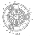
- the press can comprise a single cylinder 44 or several cylinders, for example three cylinders 44a to 44c as illustrated in FIG. 3, each cylinder comprising the same elements as that described above.
- the tool piston 65 fixed on the driving piston 64 comprises lateral bores 103 accessible to accommodate the piston rod 56 and the abutment elements 57, and a central bore 104 communicating on the one hand, with the atmosphere and, on the other hand, through a fresh air intake valve 59 with the chamber of the movable central cylinder 2.
- This fresh air intake valve 59 has its valve seat 60 formed in a plate circular 61 fixed below the lower flare 2b of the central cylinder 2.
- the piston rod of this valve is mounted in a rod guide bore produced in the body of the tool piston 65.
- the tool piston 65 is constituted by a disc fixed on the driving piston 64 by the bolts or nuts 98, 99 and a second part 66 fixed by bolts 106 on the disc 65, this second part having a lower face forming the male die 67 for drawing the metal sheet 100.
- the explosion press works as follows:
- the operating work rate of such a press is divided into three. time: fresh air intake, compression and explosion-exhaust.
- the admission of fresh air is carried out by actuation of the upper screw press of the press which raises the central piston 39 in the movable central cylinder 2 to its top dead center, and thus causes the valve to open. 59 fresh air intake and fresh air intake in the movable central cylinder 2.
- this rise of the piston 39 and its threaded rod 41 causes the press tool 3 to rise together and therefore pistons 46a to 46c in the cylinders 44a to 44c associated with their respective top dead center as well as the intake 48 and exhaust 49 valves.
- the position of the various mechanical elements during the intake phase is illustrated in FIG. 4 .
- the compression phase begins with the actuation of the upper screw press to now cause the central piston 39 to descend into the movable central cylinder 2
- the fresh air intake valve 59 is closed and the fresh air contained in the cylinder 2 is supplied under pressure through the fresh air intake duct 63 in the piston chamber 62 which causes the opening of the intake valve 48 and the closing of the exhaust valve 49.
- the air compressed by the piston 39 in the cylinder 2 is supplied to the combustion chamber 55.
- a pressure gauge not shown
- the compression phase is thus completed.
- the fuel is then injected into the combustion chambers 55 and is ignited by the aforementioned injection and ignition devices, which will cause the explosion of the gas mixture simultaneously in the three combustion chambers 55a to 55c, in the embodiment. illustrated thus causing the closing of the intake valves 48 and the transmission of the shock to the press tool via the ring 65 and therefore the stamping of the metal sheet 100.
- the composition of the gas mixture contained in the combustion chamber is proportioned according to of the work to be done and therefore of the pressing and stamping force to be obtained.
- the fuel chambers 55a to 55c are swept by the compressed air remaining contained in the central cylinder 2 below its piston 39 and in the conduits 63 for admission of fresh air. Furthermore, the cooling of the piston 39 is ensured by the admission and the discharge of the fresh air during its reciprocating movement through a channel 105 connected to the fresh air chamber 104.
- the piston 34 of the pump 14 for supplying pressurized hydraulic fluid is mounted at its point. dead high to thus move the fluid contained above the pistons 12a to 12h of the hydraulic cylinders 11a to 11h in the reservoir 33 of the feed pump, by actuation of the lower and upper screw press during the admission of fresh air in the central cylinder 2. After that, the lower screw press, the oil distribution disc 15 are blocked to prevent the passage of the fluid from the reservoir 33 in the hydraulic cylinders 11a to 11h.
- the press of the invention which can be used as a hydraulic press when no fuel is injected into the combustion chamber 55 of the cylinders 44a and 44c and simply by switching on the lower screw press and the disc 15 of hydraulic fluid distribution, is transformed into an explosion press by their blocking and the injection of a fuel into the combustion chamber of the cylinders 44a to 44c causing the explosion of this fuel mixed with fresh air admitted in this room.
- the press of the invention is of a reduced bulk and can by very simple and very rapid modifications be used according to an appropriate operating mode depending on the articles to be manufactured.
Landscapes
- Engineering & Computer Science (AREA)
- Mechanical Engineering (AREA)
- Physics & Mathematics (AREA)
- Fluid Mechanics (AREA)
- Chemical & Material Sciences (AREA)
- Combustion & Propulsion (AREA)
- General Engineering & Computer Science (AREA)
- Press Drives And Press Lines (AREA)
- Organic Low-Molecular-Weight Compounds And Preparation Thereof (AREA)
- Acyclic And Carbocyclic Compounds In Medicinal Compositions (AREA)
- Fluid-Damping Devices (AREA)
- Shaping Metal By Deep-Drawing, Or The Like (AREA)
Claims (25)
Priority Applications (1)
| Application Number | Priority Date | Filing Date | Title |
|---|---|---|---|
| AT84900019T ATE38011T1 (de) | 1982-12-20 | 1983-12-14 | Hydraulische, pneumatische, pneumatische/hydraulische oder kombinierte pneumatische/explosionspresse. |
Applications Claiming Priority (2)
| Application Number | Priority Date | Filing Date | Title |
|---|---|---|---|
| CH7400/82 | 1982-12-20 | ||
| CH7400/82A CH652647A5 (fr) | 1982-12-20 | 1982-12-20 | Presse a fonctionnement hydraulique, pneumatique, pneumatique/hydraulique, ou pneumatique/a explosion combinee. |
Publications (2)
| Publication Number | Publication Date |
|---|---|
| EP0128912A1 EP0128912A1 (de) | 1984-12-27 |
| EP0128912B1 true EP0128912B1 (de) | 1988-10-19 |
Family
ID=4324545
Family Applications (1)
| Application Number | Title | Priority Date | Filing Date |
|---|---|---|---|
| EP84900019A Expired EP0128912B1 (de) | 1982-12-20 | 1983-12-14 | Hydraulische, pneumatische, pneumatische/hydraulische oder kombinierte pneumatische/explosionspresse |
Country Status (6)
| Country | Link |
|---|---|
| US (1) | US4658629A (de) |
| EP (1) | EP0128912B1 (de) |
| CA (1) | CA1264980A (de) |
| CH (1) | CH652647A5 (de) |
| DE (1) | DE3378259D1 (de) |
| WO (1) | WO1984002492A1 (de) |
Families Citing this family (15)
| Publication number | Priority date | Publication date | Assignee | Title |
|---|---|---|---|---|
| US5010852A (en) * | 1989-04-14 | 1991-04-30 | Milisavljevic Milorad S | Heat engine |
| US5129801A (en) * | 1991-01-16 | 1992-07-14 | The United States Of America As Represented By The United States Department Of Energy | Fabrication of high temperature materials by exothermic synthesis and subsequent dynamic consolidation |
| US5415241A (en) * | 1993-08-25 | 1995-05-16 | Tac Inc. | Explosive actuated battering ram |
| NL1006721C2 (nl) * | 1997-08-05 | 1999-02-08 | Duyvis Maschf | Hydraulische pers. |
| EP1299205B1 (de) * | 2000-07-12 | 2007-10-31 | Utron Inc. | Dynamische verdichtung von pulvern unter verwendung einer gepulsten energiequelle |
| US6631668B1 (en) * | 2000-11-10 | 2003-10-14 | David Wilson | Recoilless impact device |
| US7162910B2 (en) * | 2004-06-28 | 2007-01-16 | General Electric Company | Hybrid metal forming system and method |
| US7528332B1 (en) * | 2004-11-17 | 2009-05-05 | Utron Inc. | High speed actuating device and circuit breaker |
| US10137502B1 (en) | 2006-10-20 | 2018-11-27 | Utron Kinetics, LLC | Near net shape combustion driven compaction process and refractory composite material for high temperature applications |
| US8999230B1 (en) | 2008-03-28 | 2015-04-07 | Utron Kinetics, LLC | Near net shape fabrication of high temperature components using high pressure combustion driven compaction process |
| US20100170688A1 (en) * | 2009-01-05 | 2010-07-08 | Delia Kurt J | Battering ram with replaceable heads |
| DE102014207507B4 (de) | 2014-04-17 | 2021-12-16 | Kennametal Inc. | Zerspanungswerkzeug sowie Verfahren zum Herstellen eines Zerspanungswerkzeugs |
| PL3437848T3 (pl) * | 2017-08-03 | 2024-07-15 | Nienstedt Gmbh | Obrabiarka |
| CN109358146A (zh) * | 2018-12-25 | 2019-02-19 | 成都格莱精密仪器有限公司 | 一种可快速装填色谱柱的装柱器 |
| CN117052745B (zh) * | 2023-08-31 | 2026-04-07 | 唐山盛通锻造有限公司 | 低冲击高速液压缸及高效精锻机 |
Family Cites Families (9)
| Publication number | Priority date | Publication date | Assignee | Title |
|---|---|---|---|---|
| FR1099682A (fr) * | 1954-04-23 | 1955-09-08 | Mecanique Des Fluides M D F | Transformateur hydraulique |
| US3320740A (en) * | 1965-07-02 | 1967-05-23 | Walker Mfg Co | Press |
| US3654799A (en) * | 1969-03-01 | 1972-04-11 | Becorit Grubenausbau Gmbh | Press assembly |
| SU461778A1 (ru) * | 1972-06-02 | 1975-02-28 | Гидравлический пресс | |
| GB1502980A (en) * | 1974-10-10 | 1978-03-08 | Reuti Anstalt | Fluid pressure actuated operator cylinder with incorporated stress converter |
| FR2404492A1 (fr) * | 1977-09-30 | 1979-04-27 | Lejeune Sa | Dispositif de serrage hydropneumatique d'une piece a usiner |
| US4166375A (en) * | 1978-03-28 | 1979-09-04 | Abramov Valentin S | High-speed explosive hammer |
| FR2470675A1 (fr) * | 1979-12-03 | 1981-06-12 | Warnke Umformtech Veb K | Presse hydraulique notamment pour le cisaillage de toles ou d'un materiau en barres |
| CA1186942A (en) * | 1980-12-06 | 1985-05-14 | Hermann Fusser | Floor-mounted forging press having a stationary piston with a bore for supplying a pressure medium, and a moving cylinder |
-
1982
- 1982-12-20 CH CH7400/82A patent/CH652647A5/fr not_active IP Right Cessation
-
1983
- 1983-12-14 WO PCT/CH1983/000141 patent/WO1984002492A1/de not_active Ceased
- 1983-12-14 EP EP84900019A patent/EP0128912B1/de not_active Expired
- 1983-12-14 US US06/770,864 patent/US4658629A/en not_active Expired - Fee Related
- 1983-12-14 DE DE8484900019T patent/DE3378259D1/de not_active Expired
- 1983-12-20 CA CA000443721A patent/CA1264980A/fr not_active Expired - Lifetime
Also Published As
| Publication number | Publication date |
|---|---|
| EP0128912A1 (de) | 1984-12-27 |
| WO1984002492A1 (fr) | 1984-07-05 |
| CH652647A5 (fr) | 1985-11-29 |
| US4658629A (en) | 1987-04-21 |
| DE3378259D1 (en) | 1988-11-24 |
| CA1264980C (fr) | 1990-01-30 |
| CA1264980A (fr) | 1990-01-30 |
Similar Documents
| Publication | Publication Date | Title |
|---|---|---|
| CH652647A5 (fr) | Presse a fonctionnement hydraulique, pneumatique, pneumatique/hydraulique, ou pneumatique/a explosion combinee. | |
| US3890413A (en) | Apparatus and method for compacting particulate materials | |
| FR2750173A1 (fr) | Injecteur de carburant pilote hydrauliquement par une vanne de commande directe a aiguille | |
| FR2529673A1 (fr) | Procede et appareil pour effectuer un essai de pression hydraulique sur un tube | |
| FR2497271A1 (fr) | Poussoir hydraulique extensible commande par pression | |
| CA2946481A1 (fr) | Moteur a air comprime a chambre active incluse et a distribution active a l'admission | |
| FR2638494A1 (fr) | Pompe entrainee pneumatiquement | |
| FR2646211A1 (fr) | Dispositif generateur de pression auxiliaire, notamment pour vehicule automobile | |
| KR950010069B1 (ko) | 프레스기계의 슬라이드용 쿠션·녹아우트겸용 장치의 공유압 부우스터식 구동장치 | |
| FR2514691A1 (fr) | Coussin d'emboutissage pour presses | |
| US1003987A (en) | Hydraulic press. | |
| FR2805313A1 (fr) | Pompe hydraulique mue pneumatiquement | |
| FR2497288A1 (fr) | Pompe d'injection a distributeur perfectionnee pour l'alimentation en combustible d'un moteur a combustion interne | |
| FR2585621A1 (fr) | Dispositif pour la compression ou le compactage de produits en vrac tels que des sciures de bois | |
| SU1193012A2 (ru) | Машина дл изготовлени кольцевых брикетов из порошкообразных материалов | |
| EP0530244A1 (de) | Giesseinheit für hydraulische druckgiessmaschine mit einer vorrichtung für entstörung von druckspitzen während der giessung. | |
| FR2860551A1 (fr) | Actionneur hydraulique pour moteur a combustion interne et moteur a combustion interne comportant au moins un tel actionneur hydraulique | |
| GB192128A (en) | Improvements in or relating to machines for filling and capping bottles | |
| FR2589390A1 (fr) | Presse hydraulique a courses d'ouverture et de fermeture rapides | |
| FR2677704A1 (fr) | Dispositif hydraulique de rattrapage de jeu pour distribution de moteur a combustion interne. | |
| BE340412A (de) | ||
| FR2514692A1 (fr) | Coussin d'emboutissage pour presses | |
| US779800A (en) | Hydraulic press. | |
| FR3151785A1 (fr) | Poinçon hydraulique pour presse rotative, et presse rotative équipée d’un tel poinçon | |
| FR2641721A1 (fr) | Procede d'obtention par moulage sous pression de pieces metalliques presentant des masses isolees compactes |
Legal Events
| Date | Code | Title | Description |
|---|---|---|---|
| PUAI | Public reference made under article 153(3) epc to a published international application that has entered the european phase |
Free format text: ORIGINAL CODE: 0009012 |
|
| AK | Designated contracting states |
Designated state(s): AT BE CH DE FR GB LI LU NL SE |
|
| 17P | Request for examination filed |
Effective date: 19841030 |
|
| TCAT | At: translation of patent claims filed | ||
| DET | De: translation of patent claims | ||
| 17Q | First examination report despatched |
Effective date: 19861205 |
|
| RAP3 | Party data changed (applicant data changed or rights of an application transferred) |
Owner name: PTP PATENTIERTE TECHNOLOGISCHE PROZESSE A.G. |
|
| GRAA | (expected) grant |
Free format text: ORIGINAL CODE: 0009210 |
|
| AK | Designated contracting states |
Kind code of ref document: B1 Designated state(s): AT BE CH DE FR GB LI LU NL SE |
|
| PG25 | Lapsed in a contracting state [announced via postgrant information from national office to epo] |
Ref country code: SE Effective date: 19881019 Ref country code: NL Effective date: 19881019 |
|
| REF | Corresponds to: |
Ref document number: 38011 Country of ref document: AT Date of ref document: 19881115 Kind code of ref document: T |
|
| REF | Corresponds to: |
Ref document number: 3378259 Country of ref document: DE Date of ref document: 19881124 |
|
| GBT | Gb: translation of ep patent filed (gb section 77(6)(a)/1977) | ||
| PG25 | Lapsed in a contracting state [announced via postgrant information from national office to epo] |
Ref country code: AT Effective date: 19881214 |
|
| PG25 | Lapsed in a contracting state [announced via postgrant information from national office to epo] |
Ref country code: GB Effective date: 19881219 |
|
| PG25 | Lapsed in a contracting state [announced via postgrant information from national office to epo] |
Ref country code: LU Free format text: LAPSE BECAUSE OF NON-PAYMENT OF DUE FEES Effective date: 19881231 Ref country code: BE Effective date: 19881231 |
|
| NLV1 | Nl: lapsed or annulled due to failure to fulfill the requirements of art. 29p and 29m of the patents act | ||
| BERE | Be: lapsed |
Owner name: PTP PATENTIERTE TECHNOLOGISCHE PROZESSE A.G. Effective date: 19881231 |
|
| PLBE | No opposition filed within time limit |
Free format text: ORIGINAL CODE: 0009261 |
|
| STAA | Information on the status of an ep patent application or granted ep patent |
Free format text: STATUS: NO OPPOSITION FILED WITHIN TIME LIMIT |
|
| GBPC | Gb: european patent ceased through non-payment of renewal fee | ||
| PG25 | Lapsed in a contracting state [announced via postgrant information from national office to epo] |
Ref country code: FR Free format text: LAPSE BECAUSE OF NON-PAYMENT OF DUE FEES Effective date: 19890831 |
|
| 26N | No opposition filed | ||
| REG | Reference to a national code |
Ref country code: FR Ref legal event code: ST |
|
| PGFP | Annual fee paid to national office [announced via postgrant information from national office to epo] |
Ref country code: DE Payment date: 19891110 Year of fee payment: 7 |
|
| PG25 | Lapsed in a contracting state [announced via postgrant information from national office to epo] |
Ref country code: DE Effective date: 19910903 |
|
| REG | Reference to a national code |
Ref country code: FR Ref legal event code: AR |
|
| PGFP | Annual fee paid to national office [announced via postgrant information from national office to epo] |
Ref country code: CH Payment date: 19930319 Year of fee payment: 10 |
|
| REG | Reference to a national code |
Ref country code: FR Ref legal event code: DI |
|
| PG25 | Lapsed in a contracting state [announced via postgrant information from national office to epo] |
Ref country code: LI Effective date: 19931231 Ref country code: CH Effective date: 19931231 |
|
| REG | Reference to a national code |
Ref country code: CH Ref legal event code: PL |