EP0128792A1 - Combustion process and apparatus particularly suited for the combustion of heavy fuel - Google Patents
Combustion process and apparatus particularly suited for the combustion of heavy fuel Download PDFInfo
- Publication number
- EP0128792A1 EP0128792A1 EP84400994A EP84400994A EP0128792A1 EP 0128792 A1 EP0128792 A1 EP 0128792A1 EP 84400994 A EP84400994 A EP 84400994A EP 84400994 A EP84400994 A EP 84400994A EP 0128792 A1 EP0128792 A1 EP 0128792A1
- Authority
- EP
- European Patent Office
- Prior art keywords
- zone
- combustion
- chamber
- combustible
- gases
- Prior art date
- Legal status (The legal status is an assumption and is not a legal conclusion. Google has not performed a legal analysis and makes no representation as to the accuracy of the status listed.)
- Granted
Links
Images

Classifications
-
- F—MECHANICAL ENGINEERING; LIGHTING; HEATING; WEAPONS; BLASTING
- F23—COMBUSTION APPARATUS; COMBUSTION PROCESSES
- F23C—METHODS OR APPARATUS FOR COMBUSTION USING FLUID FUEL OR SOLID FUEL SUSPENDED IN A CARRIER GAS OR AIR
- F23C3/00—Combustion apparatus characterised by the shape of the combustion chamber
- F23C3/006—Combustion apparatus characterised by the shape of the combustion chamber the chamber being arranged for cyclonic combustion
-
- F—MECHANICAL ENGINEERING; LIGHTING; HEATING; WEAPONS; BLASTING
- F23—COMBUSTION APPARATUS; COMBUSTION PROCESSES
- F23C—METHODS OR APPARATUS FOR COMBUSTION USING FLUID FUEL OR SOLID FUEL SUSPENDED IN A CARRIER GAS OR AIR
- F23C6/00—Combustion apparatus characterised by the combination of two or more combustion chambers or combustion zones, e.g. for staged combustion
- F23C6/04—Combustion apparatus characterised by the combination of two or more combustion chambers or combustion zones, e.g. for staged combustion in series connection
-
- F—MECHANICAL ENGINEERING; LIGHTING; HEATING; WEAPONS; BLASTING
- F23—COMBUSTION APPARATUS; COMBUSTION PROCESSES
- F23G—CREMATION FURNACES; CONSUMING WASTE PRODUCTS BY COMBUSTION
- F23G5/00—Incineration of waste; Incinerator constructions; Details, accessories or control therefor
- F23G5/32—Incineration of waste; Incinerator constructions; Details, accessories or control therefor the waste being subjected to a whirling movement, e.g. cyclonic incinerators
-
- F—MECHANICAL ENGINEERING; LIGHTING; HEATING; WEAPONS; BLASTING
- F23—COMBUSTION APPARATUS; COMBUSTION PROCESSES
- F23M—CASINGS, LININGS, WALLS OR DOORS SPECIALLY ADAPTED FOR COMBUSTION CHAMBERS, e.g. FIREBRIDGES; DEVICES FOR DEFLECTING AIR, FLAMES OR COMBUSTION PRODUCTS IN COMBUSTION CHAMBERS; SAFETY ARRANGEMENTS SPECIALLY ADAPTED FOR COMBUSTION APPARATUS; DETAILS OF COMBUSTION CHAMBERS, NOT OTHERWISE PROVIDED FOR
- F23M5/00—Casings; Linings; Walls
- F23M5/08—Cooling thereof; Tube walls
Definitions
- the present invention relates to a method and a device for clean combustion and applies in particular to the burning of heavy fuels.
- clean combustion is meant combustion without final emission of carbonaceous particles.
- EP 7 846 a new arrangement of the elements which amounts to making, in situ, the generation of hot gases in a first zone by imposing on said gases the form of a well-vortex flow and to introduce the material to be treated into the zone in relative depression of this flow, so as to avoid subjecting the sensitive parts of the device to the prolonged action of hot gases.
- the object of the present invention is to overcome these drawbacks.
- the combustible substance introduced into the second zone is given a low initial speed, preferably less than 10 m / s and if possible at 5 m / s, so as not to have to increase the initial amount of movement too much.
- hot dispersing gas phase the ratio of the momentum of said hot dispersing gas phase to that of the combustible substance being at least 100 but generally being preferably between 1,000 and 10,000.
- the spraying thus takes place by transfer of the momentum and an isore-distributed dispersion is obtained at the entrance to the second instantaneous zone practically instantaneous in a spectrum of fine particles which are thus in the best conditions for homogeneous and rapid vaporization.
- this spraying will be called a spraying spray.
- this avoids the pitfall of poor dispersion of a hardly flammable substance and incomplete combustion at high temperature.
- the present invention thus allows a spray quality which leads to clean combustion of heavy fuels, which, as already said, has not been possible until now.
- the second gas stream is introduced tangentially to form a helical stream which can be made well-vortex by a restricted passage delimiting the second zone.
- a material to be treated can be introduced axially into the zone in relative depression of this second flow.
- This substance is, for example, a mineral solution or suspension, based on synthetic or natural carbonates, silicas, silico-aluminates, but it can also be of an organic nature, it can also be a. residual water to be decontaminated.
- the first gas stream used to produce the well-vortex flow is advantageously constituted by air.
- the first fuel introduced can be brought either in gaseous form or in the form of a spray cloud which is obtained by any known means such as a spray nozzle of the type described in the work by MASTERS (Spray Drying), or by a device of the well-vortex flow type.
- This first fuel is preferably chosen for its ease of combustion.
- the second fuel to be treated such as heavy fuel or combustible suspension, is introduced axially into the zone in relative depression of the well-vortex flow coming from the first zone, so as to promote the suction effect due to said zone in relative depression.
- the second fuel is generally a fuel corresponding to types 4 to 6 of the ASTM standards.
- the second symmetrical well-vortex flow is obtained using an oxidizing gas such as air.
- the helical currents, introduced into a zone are advantageously under low pressure, preferably at a pressure less than 10 5 Pa relative to the pressure prevailing directly downstream of said zone when said pressure is equal to atmospheric pressure.
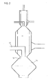
- the chamber (1) has an envelope (3) closed at its upstream part by a bottom plate (4), an annular space (6) delimited internally by a perforated wall (7), a restricted passage (10), at least a pipe (8) for tangential supply of a gaseous phase and a means for injecting fuel (5) inside the chamber (1), the casing (3) ending downstream by a convergent ( 9) in which ends, along the axis of symmetry of rotation of the chamber (1), an injection device (11), substantially at the level of the restricted passage (10), the contacting chamber (2) extending downstream the chamber (1) along the same axis of rotational symmetry and being provided with a perforated wall (12) defining an annular space (13) with its envelope (14), space in which leads to at least one tangential entry (15).
- This device can also comprise (FIG. 2) a second treatment chamber (16) of a substance introduced by a second injection device (17) disposed substantially at the level of a second restricted passage (18).
- a hot gas is generated by combustion of a first fuel.
- the material to be treated is introduced and the well-whirlpool effect located downstream of the restricted passage is used to disperse the fuel into very fine elements volume.
- the cooling of the chamber 1 is ensured by a circulation of coolant comprising an annular circulation space 22 around the chamber 1.
- This annular circulation space 22 can be replaced by a tubular assembly 23 hollowed out in the thickness of the walls of the chamber 1, as illustrated in FIG. 4, especially on a small scale.
- the temperature of the gas phase, coming from the second zone, will largely depend on the envisaged application.
- test 8 the gas from the system was rehomogenized in temperature in order to be able to carry out a thermal balance.
- the temperature measured at the center of the gas outlet pipe is 850 ° C, which taking into account the experimental inaccuracies in the measurements is entirely in agreement with a temperature rise of 735 ° C for a gas that has previously been overpressed.
- the device therefore allows the "clean" combustion of a heavy fuel (type No. 4 ASTM) with an additional fuel in the chamber (1), of the order of 1 to 10% by mass (relative to the heavy fuel )
- This system makes it possible to generate hot gases containing little or no solid particles from the least noble fuels and it is easy to imagine the economic benefits in applications such as: drying, heating, production of steam and electricity, and in general all use of "heavy" fuels, distillation residues, combustible suspensions, etc ...
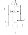
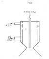
- FIG. 5 A possible diagram of this gasification treatment is illustrated in Figure 5 where P is a device according to the invention, suitable for this type of supply (diagram in Figure 6).
- a combustion with oxygen of a hydrocarbon Cm Hn is carried out, in the possible presence of CO 2 .
- a solid carbonaceous material such as ground coal is introduced, either wet or put in pneumatic transport by CO 2 , or any other means.
- zone A gasification of the solid carbonaceous material is carried out with the C0 2 introduced and the combustion gases coming from the preliminary zone P. It is optionally possible to introduce into zone A other reagents such as hydrogen for example .
- zone B rapid quenching is carried out by a third body such as water.
- This system makes it possible to produce a synthesis gas whose composition depends on the operating conditions of P and A.
Abstract
Description
La présente invention a trait à un procédé et un dispositif de combustion propre et s'applique notamment au brûlage des combustibles lourds.The present invention relates to a method and a device for clean combustion and applies in particular to the burning of heavy fuels.
Par combustibles lourds, on entend notamment :
- - soit un combustible issu de la distillation d'un pétrole brut tel qu'un fuel 4 à 6 selon norme ASTM (Burner Fuel Specification D 396 - cf Perry et Chilton Chemical Engineers Handbook - Fifth Edition 9.9) ou ce pétrole brut lui-même,
- - soit une émulsion,
- - soit une suspension partiellement ou totalement combustible d'un solide dans un liquide ou un gaz.
- - either a fuel resulting from the distillation of a crude oil such as a fuel 4 to 6 according to standard ASTM (Burner Fuel Specification D 396 - cf Perry and Chilton Chemical Engineers Handbook - Fifth Edition 9.9) or this crude oil itself ,
- - either an emulsion,
- - either a partially or completely combustible suspension of a solid in a liquid or a gas.
Par combustion propre, on entend une combustion sans émission finale de particules carbonées.By clean combustion is meant combustion without final emission of carbonaceous particles.
On sait que ce défaut représente un inconvénient majeur lors de l'utilisation des combustibles lourds. Il se traduit par le fait que l'on observe la formation, de résidus solides s'ajoutant aux cendres éventuelles.We know that this defect represents a major drawback when using heavy fuels. It results in the fact that the formation is observed, of solid residues adding to any ash.
Car, jusqu'à ce jour, ce problème n'a pu être résolu de manière satisfaisante à la connaissance de la demanderesse.Because, to date, this problem has not been resolved satisfactorily to the knowledge of the plaintiff.
Or, la demanderesse a revendiqué, dans le brevet français publié sous le N° 2 257 326, un procédé de mise en contact de substances se présentant sous des phases différentes selon lequel au moins une phase sert à former un écoulement puits-tourbillon à symétrie axiale et au moins une phase est introduite selon l'axe de symétrie dudit écoulement puits-tourbillon, jusque dans la zone en dépression relative dudit écoulement puits-tourbillon, la quantité de mouvement des éléments de volume de l'écoulement puits-tourbillon par rapport à celle des éléments de volume de la phase axiale étant telle que ledit écoulement puits-tourbillon provoque à la fois la désintégration, la dispersion et la prise en charge de la phase axiale et son traitement éventuel par l'écoulement puits-tourbillon.However, the plaintiff claimed, in the French patent published under No. 2,257,326, a method of contacting substances having different phases according to which at least one phase is used to form a well-vortex flow with symmetry axial and at least one phase is introduced along the axis of symmetry of said well-vortex flow, up to the zone in relative depression of said well-vortex flow, the momentum of the volume elements of the well-vortex flow relative to to that of the volume elements of the axial phase being such that said well-vortex flow causes both the disintegration, the dispersion and the taking over of the axial phase and its possible treatment by the well-vortex flow.
Dans le brevet français, publié sous le N° 2 276 086, on a revendiqué un procédé et un dispositif pour la génération de gaz chauds en réalisant une combustion dans la zone en dépression relative d'un écoulement hélicoidal symétrique.In the French patent, published under No. 2,276,086, a method and a device have been claimed for the generation of hot gases by carrying out combustion in the vacuum zone. relative of a symmetrical helical flow.
On a donc naturellement pensé à alimenter le dispositif selon le premier brevet avec un gaz chaud obtenu selon le procédé du second.It was therefore naturally thought to supply the device according to the first patent with a hot gas obtained according to the method of the second.
Mais l'on conçoit que l'on se soit heurté à des problèmes technologiques, en particulier dans le domaine des températures élevées.But it is understandable that we encountered technical problems, in particular in the area of high temperatures.
C'est ce qui a amené la demanderesse à revendiquer, dans l'EP 7 846, une nouvelle disposition des éléments qui revient à faire, in situ, la génération des gaz chauds dans une première zone en imposant aux dits gaz la forme d' un écoulement puits-tourbillon et à introduire la matière à traiter dans la zone en dépression relative de cet écoulement, de manière à éviter de soumettre les parties sensibles du dispositif à l'action prolongée des gaz chauds.This is what led the plaintiff to claim, in
Cette solution a permis l'utilisation de températures supérieures à celles de résistance des aciers classiques, conduisant à des résultats remarquables en ce qui concerne la distribution de taille des gouttes obtenues et par suite la vitesse de vaporisation de ces gouttes.This solution allowed the use of temperatures higher than those of resistance of conventional steels, leading to remarkable results as regards the size distribution of the drops obtained and consequently the vaporization speed of these drops.
Or, il est connu que la mise en oeuvre des combustibles lourds se heurte à des problèmes dus à l'inhomogénéité de la pulvérisation, ce qui se traduit en particulier par la formation de particules noires (suie, cénosphères...).However, it is known that the use of heavy fuels encounters problems due to the inhomogeneity of the spraying, which results in particular in the formation of black particles (soot, cenospheres, etc.).
L'objet de la présente invention est de pallier ces inconvénients.The object of the present invention is to overcome these drawbacks.
Selon le procédé de l'invention :
- a) on introduit, dans une première zone, un courant gazeux comburant selon des trajectoires hélicoidales symétriques par rapport à leur axe commun et on introduit un courant de fluide combustible, de manière à réaliser une première phase de combustion dispersante ;
- b) on force l'écoulement résultant à travers un passage restreint, dans une seconde zone, de manière à lui donner la forme d'un écoulement puits-tourbillon symétrique ;
- c) on introduit la substance combustible à traiter dans la zone en dépression relative dudit écoulement puits-tourbillon et l'on provoque une seconde combustion grâce à un second courant gazeux comburant hélicoidal dans la seconde zone, les quantités de gaz comburant et combustible introduits dans la première zone étant suffisantes pour provoquer la vaporisation de la substance à traiter à l'entrée de la seconde zone.
- a) a combustive gas stream is introduced into a first zone along helical trajectories symmetrical with respect to their common axis and a stream of combustible fluid is introduced, so as to produce a first phase of dispersing combustion;
- b) the resulting flow is forced through a restricted passage, in a second zone, so as to give it the form of a symmetrical well-vortex flow;
- c) the combustible substance to be treated is introduced into the zone in relative depression of said well-vortex flow and a second combustion is caused by a second gas stream helical oxidant in the second zone, the quantities of oxidizing gas and fuel introduced into the first zone being sufficient to cause vaporization of the substance to be treated at the entrance to the second zone.
Pratiquement, on donne à la substance combustible introduite dans la seconde zone une vitesse initiale faible, de préférence inférieure à 10 m/s et si possible à 5 m/s, de manière à ne pas devoir trop augmenter la quantité de mouvement initiale de la phase gazeuse chaude dispersante, le rapport de la quantité de mouvement de ladite phase gazeuse chaude dispersante à celle de la substance combustible étant au moins égal à 100 mais se situant généralement, de préférence, entre 1.000 et 10.000.In practice, the combustible substance introduced into the second zone is given a low initial speed, preferably less than 10 m / s and if possible at 5 m / s, so as not to have to increase the initial amount of movement too much. hot dispersing gas phase, the ratio of the momentum of said hot dispersing gas phase to that of the combustible substance being at least 100 but generally being preferably between 1,000 and 10,000.
La pulvérisation a ainsi lieu par transfert de la quantité de mouvement et on obtient une dispersion isorépartie à l'entrée de la seconde zone pratiquement instantanée en un spectre de fines particules qui se trouvent ainsi dans les meilleures conditions de vaporisation homogène et rapide .L'on qualifiera cette pulvérisation de pulvérisation vaporisante.The spraying thus takes place by transfer of the momentum and an isore-distributed dispersion is obtained at the entrance to the second instantaneous zone practically instantaneous in a spectrum of fine particles which are thus in the best conditions for homogeneous and rapid vaporization. this spraying will be called a spraying spray.
Selon l'invention, on évite ainsi l'écueil d'une mauvaise dispersion d'une substance difficilement inflammable et une combustion incomplète à haute température.According to the invention, this avoids the pitfall of poor dispersion of a hardly flammable substance and incomplete combustion at high temperature.
La présente invention permet ainsi une qualité de pulvérisation qui conduit à une combustion propre des combustibles lourds, ce qui, comme déjà dit, n'était pas possible jusqu'à ce jour.The present invention thus allows a spray quality which leads to clean combustion of heavy fuels, which, as already said, has not been possible until now.
Eventuellement, le second courant gazeux est introduit tangentiellement pour former un courant hélicoidal que l'on peut rendre puits-tourbillon par un passage restreint délimitant la deuxième zone. Dans ce cas, une matière à traiter peut être introduite axialement dans la zone en dépression relative de ce second écoulement. Cette substance est, par exemple, une solution ou suspension minérale, à base de carbonates synthétiques ou naturels, de silices, de silico-aluminates, mais elle peut aussi être de nature organique, ce peut aussi être une. eau résiduelle à dépolluer.Optionally, the second gas stream is introduced tangentially to form a helical stream which can be made well-vortex by a restricted passage delimiting the second zone. In this case, a material to be treated can be introduced axially into the zone in relative depression of this second flow. This substance is, for example, a mineral solution or suspension, based on synthetic or natural carbonates, silicas, silico-aluminates, but it can also be of an organic nature, it can also be a. residual water to be decontaminated.
Le premier courant gazeux servant à réaliser l'écoulement puits-tourbillon est avantageusement constitué par de l'air.The first gas stream used to produce the well-vortex flow is advantageously constituted by air.
Le premier combustible introduit peut être amené soit sous forme gazeuse, soit sous forme d'un nuage de pulvérisation qui est obtenu par tout moyen connu tel que buse de pulvérisation du type de celle décrite dans l'ouvrage de MASTERS (Spray Drying), soit par un dispositif du type à écoulement puits-tourbillon.The first fuel introduced can be brought either in gaseous form or in the form of a spray cloud which is obtained by any known means such as a spray nozzle of the type described in the work by MASTERS (Spray Drying), or by a device of the well-vortex flow type.
Ce premier combustible est choisi de préférence pour sa facilité de combustion.This first fuel is preferably chosen for its ease of combustion.
Il est donc situé dans la gamme des combustibles coûteux, eu égard aux combustibles lourds, et on aura donc intérêt à en réduire la proportion par rapport au dit combustible lourd.It is therefore located in the range of expensive fuels, having regard to heavy fuels, and it will therefore be advantageous to reduce the proportion thereof relative to said heavy fuel.
Le deuxième combustible qui est à traiter, tel que fuel lourd ou suspension combustible, est introduit axialement dans la zone en dépression relative de l'écoulement puits-tourbillon issu de la première zone, de manière à favoriser l'effet de succion dû à ladite zone en dépression relative.The second fuel to be treated, such as heavy fuel or combustible suspension, is introduced axially into the zone in relative depression of the well-vortex flow coming from the first zone, so as to promote the suction effect due to said zone in relative depression.
Le second combustible est généralement un combustible correspondant aux types 4 à 6 des normes ASTM.The second fuel is generally a fuel corresponding to types 4 to 6 of the ASTM standards.
Le second écoulement puits-tourbillon symétrique est obtenu à l'aide d'un gaz comburant tel que l'air.The second symmetrical well-vortex flow is obtained using an oxidizing gas such as air.
Les courants hélicoïdaux, introduits dans une zone le sont avantageusement sous faible pression, de préférence à une pression inférieure à 105 Pa par rapport à la pression régnant directement en aval de ladite zone lorsque ladite pression est égale à la pression atmosphérique.The helical currents, introduced into a zone are advantageously under low pressure, preferably at a pressure less than 10 5 Pa relative to the pressure prevailing directly downstream of said zone when said pressure is equal to atmospheric pressure.
Le procédé selon l'invention peut être mis en oeuvre par un dispositif selon l'EP 7846 qui comprend (Fig. 1)
- - une première chambre (1) de combustion correspondant à la
zone 1 - - une chambre de mise en contact et de combustion (2) correspondant à la
zone 2.
- - a first combustion chamber (1) corresponding to
zone 1 - - a contacting and combustion chamber (2) corresponding to
zone 2.
La chambre (1) présente une enveloppe (3) fermée à sa partie amont par une plaque de fond (4), un espace annulaire (6) délimité intérieurement par une paroi perforée (7), un passage restreint (10), au moins un conduit (8) d'amenée tangentielle d'une phase gazeuse et un moyen d'injection du carburant (5) à l'intérieur de la chambre (1), l'enveloppe (3) se terminant en aval par un convergent (9) dans lequel aboutit, selon l'axe de symétrie de rotation de la chambre (1), un dispositif d'injection (11), sensiblement au niveau du passage restreint (10), la chambre de mise en contact (2) prolongeant en aval la chambre (1) selon le même axe de symétrie de rotation et étant pourvue d'une paroi perforée (12) définissant un espace annulaire (13) avec son enveloppe (14), espace dans lequel aboutit au moins une entrée tangentielle (15).The chamber (1) has an envelope (3) closed at its upstream part by a bottom plate (4), an annular space (6) delimited internally by a perforated wall (7), a restricted passage (10), at least a pipe (8) for tangential supply of a gaseous phase and a means for injecting fuel (5) inside the chamber (1), the casing (3) ending downstream by a convergent ( 9) in which ends, along the axis of symmetry of rotation of the chamber (1), an injection device (11), substantially at the level of the restricted passage (10), the contacting chamber (2) extending downstream the chamber (1) along the same axis of rotational symmetry and being provided with a perforated wall (12) defining an annular space (13) with its envelope (14), space in which leads to at least one tangential entry (15).
Ce dispositif peut également comprendre (Fig. 2) une seconde chambre de traitement (16) d'une substance introduite par un second dispositif d'injection (17) disposé sensiblement au niveau d'un second passage restreint (18).This device can also comprise (FIG. 2) a second treatment chamber (16) of a substance introduced by a second injection device (17) disposed substantially at the level of a second restricted passage (18).
Dans la chambre (1), on génère un gaz chaud par combustion d'un premier combustible.In the chamber (1), a hot gas is generated by combustion of a first fuel.
Au niveau du passage restreint (10) séparant la chambre (1) de la chambre (2), on introduit la matière à traiter et on utilise l'effet puits-tourbillon localisé en aval du passage restreint pour disperser le combustible en très fins éléments de volume.At the restricted passage (10) separating the chamber (1) from the chamber (2), the material to be treated is introduced and the well-whirlpool effect located downstream of the restricted passage is used to disperse the fuel into very fine elements volume.
Dans un cas simple où les gaz comburants sont constitués par de l'air et où le premier combustible est un hydrocarbure gazeux, les conditions normales de marche pour ce dispositif sont les suivantes :
- - la température minimale de pulvérisation vaporisante du combustible lourd est compris entre 150 et 300° C, à l'issue de la zone d'isorépartition,
- - la température de la phase gazeuse issue de la
zone 1 est compris entre 400 et 1000°C. - - le rapport massique de la quantité d'air introduit dans la
zone 2, par rapport à celle de l'air introduit dans lazone 1, est compris entre 1 et 100, cette dernière valeur étant fonction de la température finale visée enzone 2 - - le rapport massique de la quantité de combustible introduit dans la
zone 1, par rapport à celle introduite dans lazone 2, est compris entre 0,01 et 0,1.
- - the minimum vaporizing spray temperature of heavy fuel is between 150 and 300 ° C, at the end of the isorepartition zone,
- - the temperature of the gas phase from
zone 1 is between 400 and 1000 ° C. - the mass ratio of the quantity of air introduced into
zone 2, relative to that of the air introduced intozone 1, is between 1 and 100, this latter value being a function of the final temperature targeted inzone 2 - - The mass ratio of the quantity of fuel introduced into
zone 1, compared to that introduced intozone 2, is between 0.01 and 0.1.
Bien entendu, ces conditions de marche pourront être modifiées en fonction :
- - de la nature du courant gazeux comburant introduit dans la zone 1 : par exemple oxygène au lieu d'air,
- - de la nature du combustible introduit dans la zone 1 : par exemple hydrogène. Dans le cas où on vise une température dans la
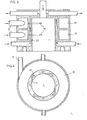
zone 1 plus élevée, de l'ordre de 1000 à 2500°C notamment lorsqu'on utilise l'oxygène comme comburant, on met en oeuvre préférentiellement le dispositif illustré à la Fig. 3 qui présente une chambre 1, dans laquelle débouchent tangentiellement les entrées 19 reliantla chambre 1 à des tores dedistribution 20 alimentés par des tubulures 21.
- - the nature of the oxidizing gas stream introduced into zone 1: for example oxygen instead of air,
- - the nature of the fuel introduced into zone 1: for example hydrogen. In the case where a higher temperature in
zone 1 is targeted, of the order of 1000 to 2500 ° C., in particular when uses oxygen as oxidant, the device illustrated in FIG. 1 is preferably used. 3 which has achamber 1, into which theinlets 19 tangentially open connecting thechamber 1 todistribution toroids 20 supplied bypipes 21.
Le refroidissement de la chambre 1 est assuré par une circulation de liquide de refroidissement comprenant un espace annulaire de circulation 22 autour de la chambre 1.The cooling of the
Cet espace annulaire de circulation 22 peut être remplacé par un ensemble tubulaire 23 creusé dans l'épaisseur des parois de la chambre 1, comme illustré à la Fig. 4, en particulier à petite échelle.This
La température de la phase gazeuse, issue de la seconde zone, va dépendre largement de l'application envisagée.The temperature of the gas phase, coming from the second zone, will largely depend on the envisaged application.
Enfin, toutes ces conditions dépendront également de la nature du combustible à vaporiser.Finally, all these conditions will also depend on the nature of the fuel to be vaporized.
A l'aide du dispositif illustré Fig. 1, on a réalisé les essais résumés dans le tableau suivant :

Lors de l'essai 8, on a réhomogénéisé en température le gaz issu du système afin de pouvoir faire un bilan thermique.During test 8, the gas from the system was rehomogenized in temperature in order to be able to carry out a thermal balance.

- Entrée : 54,4 kg/h x 1,096 kJ/kg °C x 950°C = 56 848 kJ/heureInput: 54.4 kg / h x 1.096 kJ / kg ° C x 950 ° C = 56 848 kJ / hour
- Génération : 19.9 kg/h x 41 840 kJ/kg = 832 616 kJ/hGeneration: 19.9 kg / h x 41,840 kJ / kg = 832,616 kJ / h
- Sortie : 1123 kg/h x 1,075 kJ/kg °C x t °C d'où t° C = 735°COutput: 1123 kg / h x 1.075 kJ / kg ° C x t ° C hence t ° C = 735 ° C
La température mesurée au centre de la canalisation de sortie des gaz est de 850° C, ce qui compte tenu des imprécisions expérimentales sur les mesures est tout à fait en accord avec une élévation de température de 735°C pour un gaz préalablement surpressé.The temperature measured at the center of the gas outlet pipe is 850 ° C, which taking into account the experimental inaccuracies in the measurements is entirely in agreement with a temperature rise of 735 ° C for a gas that has previously been overpressed.
L'intérêt de la présente invention peut être facilement apppré- hendé de la manière suivante :
- - lorsque la combustion dans la chambre (1) a lieu, la paroi interne de la chambre (2) est toujours froide et très propre et le reste durant toute l'expérience ;
- - lorsque l'on coupe l'alimentation du combustible dans la zone (1), on observe :
- - que les parois de la chambre (2) se salissent très rapidement (chemisage de fuel liquide fondu noir), à mesure que la température des gaz de pulvérisation décroît,
- - que la flamme change d'aspect (devient plus éclairante) et que les gaz de combustion se chargent d'imbrûlés,
- - que l'on atteint facilement l'extinction dans la chambre (2).
- - When combustion in the chamber (1) takes place, the internal wall of the chamber (2) is always cold and very clean and the rest during the whole experiment;
- - when the fuel supply is cut off in zone (1), we observe:
- - that the walls of the chamber (2) get dirty very quickly (lining of black molten liquid fuel), as the temperature of the spraying gases decreases,
- - the flame changes its appearance (becomes more illuminating) and the combustion gases become charged with unburnt,
- - that extinction is easily reached in the chamber (2).
Il est important de noter que, pour environ 20 kg/h de combustible totalement brûlés, la chambre (2) a pour dimensions :
- - diamètre : 180 mm
- - longueur : 500 mm et que, en paroi froide, il se dégage donc de l'ordre de 63.106 kJ/h.m3, valeur très élevée par rapport à celles qui caractérisent les brûleurs classiques. De telles dimensions sont normalement incompatibles avec une combustion de combustible lourd, surtout à de tels débits, en présence de paroi froide ce que la coupure d'alimentation du combustible en zone(l) confirme d'ailleurs systématiquement.
- - diameter: 180 mm
- - length: 500 mm and that, on a cold wall, it therefore emerges on the order of 63.10 6 kJ / hm 3 , a very high value compared to those which characterize conventional burners. Such dimensions are normally incompatible with combustion of heavy fuel, especially at such flow rates, in the presence of a cold wall, which the fuel supply cut-off in zone (1) moreover systematically confirms.
Le dispositif permet donc la combustion "propre" d'un combustible lourd (type N° 4 ASTM) avec un appoint de combustible dans la chambre (1), de l'ordre de 1 à 10 % en masse (par rapport au combustible lourd)The device therefore allows the "clean" combustion of a heavy fuel (type No. 4 ASTM) with an additional fuel in the chamber (1), of the order of 1 to 10% by mass (relative to the heavy fuel )
On a déterminé les conditions opératoires :
- Pour 1000 kg/h de nonadécane : chaleur de vaporisation = 356 kJ/kg à 25° C chaleur de combustion = 44 279 kJ/kg
- For 1000 kg / h of nonadecane: heat of vaporization = 356 kJ / kg at 25 ° C heat of combustion = 44,279 kJ / kg
Ces conditions sont rassemblées dans le tableau ci-après :

Ce système permet de générer des gaz chauds ne contenant pas ou très peu de particules solides à partir de combustibles les moins nobles et on imagine facilement les retombées économiques dans des applications telles que : séchage, chauffage, production de vapeur et électricité, et en général toute utilisation de combustibles "lourds", résidus de distillations, suspensions combustibles, etc...This system makes it possible to generate hot gases containing little or no solid particles from the least noble fuels and it is easy to imagine the economic benefits in applications such as: drying, heating, production of steam and electricity, and in general all use of "heavy" fuels, distillation residues, combustible suspensions, etc ...
On observe, en effet, une "flamme de gaz" beaucoup moins lumineuse (c'est-à-dire contenant moins de particules solides rayonnantes) lorsqu'on réalise la pulvérisation vaporisante du combustible par du gaz chaud que dans le cas où l'on se contente d'une simple pulvérisation dans l'air de combustion.We observe, in fact, a much less luminous "gas flame" (that is to say containing less radiant solid particles) when the vaporizing spraying of the fuel is carried out with hot gas than in the case where the we are content with a simple spraying into the combustion air.
Par ailleurs, le dispositif d'introduction du combustible principal impose peu de perte de charge à son écoulement. Il permet donc l'injection d'un mélange constitué de plusieurs phases (bouillies ou transports pneumatiques denses) ou de plusieurs de ces mélanges copulvérisés (introduction coaxiale par exemple) ce qui présente les avantages suivants par rapport aux techniques actuelles
- 1) très peu de pression motrice nécessaire (<3.10 Pa par exemple si la combustion a lieu aux environs de la pression atmosphérique), donc dispositifs simples de pompage non soumis à l'abrasion
- 2) pas de système d'ajutage pulvérisant soumis à une abrasion forte
- 3) possibilité de co-injection de produit traitant in situ, dans la flamme même, les éventuels sous-produits indésirables naissant dans la combustion (S02 par exemple).
- 1) very little driving pressure required (<3.10 Pa for example if combustion takes place around atmospheric pressure), therefore simple pumping devices not subject to abrasion
- 2) no spraying nozzle system subjected to strong abrasion
- 3) possibility of co-injection of product treating in situ, in the flame itself, any undesirable by-products arising in combustion (S0 2 for example).
Les produits co-injectés (tels que carbonates très fins) peuvent l'être :
- - séparément : solution, bouillie, transport pneumatique
- - ou en mélange : suspension stabilisée.
- - separately: solution, slurry, pneumatic transport
- - or as a mixture: stabilized suspension.
4) possibilité de traitement, par des gaz chauds, de mélanges à base de charbon, ces gaz contenant de l'oxygène, en vue soit de la combustion totale du carbone, soit de sa combustion partielle en présence d'oxydants de ce carbone visant à sa "gazéification" (vapeur d'eau et/ou gaz carbonique par exemple).4) possibility of treatment, with hot gases, of coal-based mixtures, these gases containing oxygen, with a view either to the total combustion of the carbon, or to its partial combustion in the presence of oxidants of this carbon aimed to its "gasification" (water vapor and / or carbon dioxide for example).
Un schéma possible de ce traitement de gazéification est illustré à la figure 5 où P est un dispositif selon l'invention, adapté à ce type d'alimentation (schéma de principe figure 6).A possible diagram of this gasification treatment is illustrated in Figure 5 where P is a device according to the invention, suitable for this type of supply (diagram in Figure 6).
Dans une zone préliminaire P, on réalise une combustion à l'oxygène d'un hydrocarbure Cm Hn, en présence éventuelle de CO2.In a preliminary zone P, a combustion with oxygen of a hydrocarbon Cm Hn is carried out, in the possible presence of CO 2 .
Au niveau du passage restreint caractérisant le dispositif selon l'invention, on introduit une matière carbonée solide telle que charbon broyé, soit humide, soit mis en transport pneumatique par du CO2, ou tout autre moyen.At the restricted passage characterizing the device according to the invention, a solid carbonaceous material such as ground coal is introduced, either wet or put in pneumatic transport by CO 2 , or any other means.
A la figure 5 sont explicités les débits respectifs d'alimentation des zones P et A : pour 1 de carbone, on introduit W Cm Hn, XO2, Y CO2, ZH2' Cm Hn désignant soit de l'hydrogène, soit un hydrocarbure.In Figure 5 are explained the respective feed rates of zones P and A: for 1 of carbon, we introduce W Cm Hn, XO 2 , Y CO 2 , ZH 2 ' Cm Hn denoting either hydrogen, or a hydrocarbon.
Dans la zone A, on réalise la gazéification de la matière carbonée solide par le C02 introduit et les gaz de combustion issus de la zone préliminaire P. On peut éventuellement introduire dans la zone A d'autres réactifs tels que l'hydrogène par exemple.In zone A, gasification of the solid carbonaceous material is carried out with the C0 2 introduced and the combustion gases coming from the preliminary zone P. It is optionally possible to introduce into zone A other reagents such as hydrogen for example .
Enfin, dans la zone B, on réalise une trempe rapide par un tiers corps tel que de l'eau.Finally, in zone B, rapid quenching is carried out by a third body such as water.
Ce système permet de produire un gaz de synthèse dont la composition dépend des conditions opératoires de P et de A.This system makes it possible to produce a synthesis gas whose composition depends on the operating conditions of P and A.
Claims (10)
Priority Applications (1)
| Application Number | Priority Date | Filing Date | Title |
|---|---|---|---|
| AT84400994T ATE28695T1 (en) | 1983-05-20 | 1984-05-16 | COMBUSTION PROCESS AND APPARATUS PARTICULARLY SUITED FOR THE COMBUSTION OF HEAVY FUEL. |
Applications Claiming Priority (2)
| Application Number | Priority Date | Filing Date | Title |
|---|---|---|---|
| FR8308393A FR2551183B1 (en) | 1983-05-20 | 1983-05-20 | OWN COMBUSTION PROCESS AND DEVICE APPLICABLE IN PARTICULAR TO THE BURNING OF HEAVY FUELS |
| FR8308393 | 1983-05-20 |
Publications (2)
| Publication Number | Publication Date |
|---|---|
| EP0128792A1 true EP0128792A1 (en) | 1984-12-19 |
| EP0128792B1 EP0128792B1 (en) | 1987-07-29 |
Family
ID=9289035
Family Applications (1)
| Application Number | Title | Priority Date | Filing Date |
|---|---|---|---|
| EP84400994A Expired EP0128792B1 (en) | 1983-05-20 | 1984-05-16 | Combustion process and apparatus particularly suited for the combustion of heavy fuel |
Country Status (6)
| Country | Link |
|---|---|
| US (1) | US4526529A (en) |
| EP (1) | EP0128792B1 (en) |
| JP (1) | JPS6048407A (en) |
| AT (1) | ATE28695T1 (en) |
| DE (1) | DE3465138D1 (en) |
| FR (1) | FR2551183B1 (en) |
Cited By (7)
| Publication number | Priority date | Publication date | Assignee | Title |
|---|---|---|---|---|
| FR2592321A1 (en) * | 1986-01-02 | 1987-07-03 | Rhone Poulenc Chim Base | PROCESS FOR OBTAINING A HIGH TEMPERATURE GASEOUS PHASE, AND DEVICE FOR CARRYING OUT THIS PROCESS. APPLICATION TO THE TREATMENT OF LIQUID OR GASEOUS PHASES, WITH OR WITHOUT SOLIDS, AND SPRAY SOLIDS. |
| EP0463277A1 (en) * | 1989-05-22 | 1992-01-02 | Institute of Gas Technology | Process and apparatus for ultra-low pollutant emission combustion |
| US5158445A (en) * | 1989-05-22 | 1992-10-27 | Institute Of Gas Technology | Ultra-low pollutant emission combustion method and apparatus |
| FR2698156A1 (en) * | 1992-11-16 | 1994-05-20 | Rhone Poulenc Chimie | A method of heat treating an effluent comprising polluting organic material or an inorganic compound. |
| EP0834039A1 (en) * | 1992-06-10 | 1998-04-08 | Donald C. Jensen | Energy converter using imploding plasma vortex heating |
| WO2000032988A1 (en) * | 1998-11-18 | 2000-06-08 | Bernardini, Mario | Reactor for afterburning of gases resulting from combustion |
| WO2010018347A1 (en) * | 2008-08-13 | 2010-02-18 | Vichem (Sas) | Method and device for heat treating at least one effluent comprising fuel pollutants |
Families Citing this family (12)
| Publication number | Priority date | Publication date | Assignee | Title |
|---|---|---|---|---|
| FR2257326B1 (en) * | 1973-06-19 | 1976-05-28 | Rhone Progil | |
| US4676736A (en) * | 1985-01-31 | 1987-06-30 | Gas Research Institute | Combustion device for combustion of a gaseous fuel |
| DE3503413A1 (en) * | 1985-02-01 | 1986-08-07 | Christian Dr.-Ing. 8570 Pegnitz Koch | METHOD AND DEVICE FOR THE FOUR-STAGE COMBUSTION OF GASEOUS AND LIQUID FUELS WITH NON-OXYGEN-FREE EXHAUST GASES |
| US5766000A (en) * | 1995-06-06 | 1998-06-16 | Beloit Technologies, Inc. | Combustion chamber |
| US5641412A (en) * | 1995-10-16 | 1997-06-24 | Guy; Christophe | Free radical oxidation process and installation for treating liquid effluents contaminated by organic substances |
| US5948373A (en) * | 1995-10-16 | 1999-09-07 | Corporation De L'ecole Polytechnique | Free radical oxidation installation for treating liquid effluents contaminated by organic substances |
| US6079974A (en) * | 1997-10-14 | 2000-06-27 | Beloit Technologies, Inc. | Combustion chamber to accommodate a split-stream of recycled gases |
| KR100330814B1 (en) * | 2000-11-22 | 2002-04-03 | (주)씨디에스글로벌 | Centrifugal Combusting Method using the Air-flow in a Furnace |
| CN100498059C (en) * | 2005-11-11 | 2009-06-10 | 华南理工大学 | Clean heating air stove with water-coal slurry fuel |
| KR100886190B1 (en) * | 2007-11-12 | 2009-02-27 | 한국에너지기술연구원 | The burner for making deoxidizing atmosphere of exhaust gas in engine cogeneration plant with denox process |
| BR112013021252A2 (en) * | 2011-02-21 | 2019-09-24 | Lp Amina Llc | cyclone reactor, and method for producing a usable by-product using the same |
| JP6454860B2 (en) * | 2014-11-12 | 2019-01-23 | 株式会社イーコンセプト | Combustion accelerator and heating device using the same |
Citations (7)
| Publication number | Priority date | Publication date | Assignee | Title |
|---|---|---|---|---|
| DE1122054B (en) * | 1960-04-16 | 1962-01-18 | Hoechst Ag | Process for the production of low molecular weight unsaturated hydrocarbons |
| FR2406610A1 (en) * | 1977-10-20 | 1979-05-18 | Rhone Poulenc Ind | Treating waste water contg. oxidisable material, esp. sulphur derivs. - by continuous single-stage process comprising simultaneous atomisation and oxidation in oxidising gas vortex |
| EP0007846A1 (en) * | 1978-07-21 | 1980-02-06 | Rhone-Poulenc Chimie De Base | Device for treating substances of different phases such as liquid, semi-liquid or pasty substances, by another phase, particularly a gaseous phase |
| GB2059031A (en) * | 1979-09-14 | 1981-04-15 | Univ Malaya | Improvements relating to cyclone- type furnaces |
| EP0048664A1 (en) * | 1980-09-24 | 1982-03-31 | Rhone-Poulenc Chimie De Base | Process for the treatment of a liquid resulting in solid wastes by the action of a fluid and at least one gas phase |
| EP0073265A1 (en) * | 1981-08-31 | 1983-03-09 | Phillips Petroleum Company | Method and apparatus for burning a fuel |
| US4382771A (en) * | 1980-05-12 | 1983-05-10 | Lola Mae Carr | Gas and steam generator |
Family Cites Families (7)
| Publication number | Priority date | Publication date | Assignee | Title |
|---|---|---|---|---|
| US3376098A (en) * | 1966-08-29 | 1968-04-02 | Phillips Petroleum Co | Two-chamber burner and process |
| JPS5027210A (en) * | 1973-07-04 | 1975-03-20 | ||
| FR2276086A1 (en) * | 1974-06-28 | 1976-01-23 | Rhone Poulenc Ind | METHOD AND APPARATUS FOR ENSURING A REACTION BETWEEN FLUID CURRENTS |
| US4124353A (en) * | 1975-06-27 | 1978-11-07 | Rhone-Poulenc Industries | Method and apparatus for carrying out a reaction between streams of fluid |
| JPS525021A (en) * | 1975-07-01 | 1977-01-14 | Uroko Seisakusho:Kk | Combustion apparatus for powdered or pulverized materials |
| JPS55165405A (en) * | 1979-06-07 | 1980-12-23 | Mitsubishi Heavy Ind Ltd | Combustion method with reduced amount of nitrogen oxide |
| US4427362A (en) * | 1980-08-14 | 1984-01-24 | Rockwell International Corporation | Combustion method |
-
1983
- 1983-05-20 FR FR8308393A patent/FR2551183B1/en not_active Expired
-
1984
- 1984-05-16 AT AT84400994T patent/ATE28695T1/en not_active IP Right Cessation
- 1984-05-16 DE DE8484400994T patent/DE3465138D1/en not_active Expired
- 1984-05-16 EP EP84400994A patent/EP0128792B1/en not_active Expired
- 1984-05-18 JP JP59100338A patent/JPS6048407A/en active Granted
- 1984-05-21 US US06/612,543 patent/US4526529A/en not_active Expired - Lifetime
Patent Citations (7)
| Publication number | Priority date | Publication date | Assignee | Title |
|---|---|---|---|---|
| DE1122054B (en) * | 1960-04-16 | 1962-01-18 | Hoechst Ag | Process for the production of low molecular weight unsaturated hydrocarbons |
| FR2406610A1 (en) * | 1977-10-20 | 1979-05-18 | Rhone Poulenc Ind | Treating waste water contg. oxidisable material, esp. sulphur derivs. - by continuous single-stage process comprising simultaneous atomisation and oxidation in oxidising gas vortex |
| EP0007846A1 (en) * | 1978-07-21 | 1980-02-06 | Rhone-Poulenc Chimie De Base | Device for treating substances of different phases such as liquid, semi-liquid or pasty substances, by another phase, particularly a gaseous phase |
| GB2059031A (en) * | 1979-09-14 | 1981-04-15 | Univ Malaya | Improvements relating to cyclone- type furnaces |
| US4382771A (en) * | 1980-05-12 | 1983-05-10 | Lola Mae Carr | Gas and steam generator |
| EP0048664A1 (en) * | 1980-09-24 | 1982-03-31 | Rhone-Poulenc Chimie De Base | Process for the treatment of a liquid resulting in solid wastes by the action of a fluid and at least one gas phase |
| EP0073265A1 (en) * | 1981-08-31 | 1983-03-09 | Phillips Petroleum Company | Method and apparatus for burning a fuel |
Cited By (15)
| Publication number | Priority date | Publication date | Assignee | Title |
|---|---|---|---|---|
| FR2592321A1 (en) * | 1986-01-02 | 1987-07-03 | Rhone Poulenc Chim Base | PROCESS FOR OBTAINING A HIGH TEMPERATURE GASEOUS PHASE, AND DEVICE FOR CARRYING OUT THIS PROCESS. APPLICATION TO THE TREATMENT OF LIQUID OR GASEOUS PHASES, WITH OR WITHOUT SOLIDS, AND SPRAY SOLIDS. |
| EP0232658A1 (en) * | 1986-01-02 | 1987-08-19 | Rhone-Poulenc Chimie | Process and device for exothermic reaction of gases |
| US4931012A (en) * | 1986-01-02 | 1990-06-05 | Rhone-Poulenc Chimie De Base | Phase contactor/process for generating high temperature gaseous phase |
| EP0463277A1 (en) * | 1989-05-22 | 1992-01-02 | Institute of Gas Technology | Process and apparatus for ultra-low pollutant emission combustion |
| US5158445A (en) * | 1989-05-22 | 1992-10-27 | Institute Of Gas Technology | Ultra-low pollutant emission combustion method and apparatus |
| EP0834039A4 (en) * | 1992-06-10 | 1999-06-09 | Donald C Jensen | Energy converter using imploding plasma vortex heating |
| EP0834039A1 (en) * | 1992-06-10 | 1998-04-08 | Donald C. Jensen | Energy converter using imploding plasma vortex heating |
| EP0598639A1 (en) * | 1992-11-16 | 1994-05-25 | Rhone-Poulenc Chimie | Process for the thermal treatment of an effluent containing organic polluting materials or an inorganic compound |
| US5817909A (en) * | 1992-11-16 | 1998-10-06 | Rhone-Poulenc Chimie | Purification of waste/industrial effluents comprising organic/inorganic pollutants |
| FR2698156A1 (en) * | 1992-11-16 | 1994-05-20 | Rhone Poulenc Chimie | A method of heat treating an effluent comprising polluting organic material or an inorganic compound. |
| WO2000032988A1 (en) * | 1998-11-18 | 2000-06-08 | Bernardini, Mario | Reactor for afterburning of gases resulting from combustion |
| WO2010018347A1 (en) * | 2008-08-13 | 2010-02-18 | Vichem (Sas) | Method and device for heat treating at least one effluent comprising fuel pollutants |
| FR2935041A1 (en) * | 2008-08-13 | 2010-02-19 | Vichem | METHOD AND DEVICE FOR THERMALLY TREATING AT LEAST ONE EFFLUENT COMPRISING COMBUSTIBLE POLLUTANTS |
| EP2784387A2 (en) | 2008-08-13 | 2014-10-01 | Vichem (SA) | Combustion chamber for thermal treatment of at least one effluent comprising combustible pollutants |
| EP2784387A3 (en) * | 2008-08-13 | 2015-11-18 | Vichem (SA) | Combustion chamber for thermal treatment of at least one effluent comprising combustible pollutants |
Also Published As
| Publication number | Publication date |
|---|---|
| ATE28695T1 (en) | 1987-08-15 |
| US4526529A (en) | 1985-07-02 |
| EP0128792B1 (en) | 1987-07-29 |
| FR2551183B1 (en) | 1988-05-13 |
| JPS6048407A (en) | 1985-03-16 |
| JPH0346722B2 (en) | 1991-07-17 |
| FR2551183A1 (en) | 1985-03-01 |
| DE3465138D1 (en) | 1987-09-03 |
Similar Documents
| Publication | Publication Date | Title |
|---|---|---|
| EP0128792B1 (en) | Combustion process and apparatus particularly suited for the combustion of heavy fuel | |
| CA2831483C (en) | Method for obtaining carbon black from rubber waste and device thereof | |
| FR2547020A1 (en) | METHOD AND APPARATUS FOR COMBUSTING A WATER-LIKE EMULSION IN OIL | |
| BRPI0620432A2 (en) | Fuel additive for increasing the combustion characteristics of a high carbon asphaltene fuel, a method to improve its characteristics and fuel | |
| EA013093B1 (en) | Method for producing water-fuel emulsion and composite multi-component fuel | |
| Vaitilingom et al. | Development of rape seed oil burners for drying and heating | |
| FR2492392A1 (en) | HIGH ENERGY EFFICIENCY PROCESS FOR THE PRODUCTION OF CARBON-BLACK | |
| BE541935A (en) | MANUFACTURE OF BLACK SMOKE | |
| FR2567624A1 (en) | HIGH TEMPERATURE HOT AIR GENERATOR FOR DRYING INSTALLATION FOR EXAMPLE OF BRICKWARE, CEMENT PLANTS OR AGRICULTURAL PRODUCTS, FOR HEATING PREMISES | |
| EP1247046B1 (en) | Method and device for the autocombustion of oily organic waste, comprising a tangential heating furnace | |
| US2247181A (en) | Carburetor for hydrocarbon fuels | |
| Kumar et al. | Investigation on combustion characteristics of acetone-butanol-ethanol/Jet A-1 mixture in a Swirl-stabilized combustor for its potential application in gas turbine engines | |
| FR2664022A1 (en) | METHOD AND DEVICE FOR GENERATING HEAT HAVING EFFLUENT DESULFURIZATION WITH FINE GRANULOMETRY ABSORBENT PARTICLES IN TRANSPORTED BED. | |
| RU2706168C1 (en) | Burner device and method of fuel combustion flame arrangement | |
| CA1302090C (en) | Process for the production of a high temperature gaseous phase and device for this process, and its application to liquid or gaseous phases, containing solid matters and sprayablesolids | |
| RU2678310C1 (en) | Pulverized coal fuel for burning preparation method | |
| FR2535334A1 (en) | BURNER BLACK OF CARBON | |
| Noge et al. | An investigation into the relationship between the formation of thermal cracked components and PM reduction during diesel combustion using water emulsified fuel | |
| EP0694600B1 (en) | Process and installation for the production of fuels | |
| WO2008000975A1 (en) | Burner for producing the combustion of substances believed to be difficult to burn | |
| RU2815849C1 (en) | Device for combustion of mixture of solid low-grade fuel with granules of methane hydrate | |
| FR2691524A1 (en) | Disposal of radioactive graphite without contaminating environment - by pulverising, mixing with water and burning, then purifying combustion gases and recycling unburnt solids | |
| CH122316A (en) | Process for the production of a combustible gas mixture. | |
| BE416499A (en) | ||
| BE496652A (en) |
Legal Events
| Date | Code | Title | Description |
|---|---|---|---|
| PUAI | Public reference made under article 153(3) epc to a published international application that has entered the european phase |
Free format text: ORIGINAL CODE: 0009012 |
|
| AK | Designated contracting states |
Designated state(s): AT BE CH DE FR GB IT LI LU NL SE |
|
| 17P | Request for examination filed |
Effective date: 19850109 |
|
| ITF | It: translation for a ep patent filed |
Owner name: D. PERROTTA & C. S.A.S. |
|
| GRAA | (expected) grant |
Free format text: ORIGINAL CODE: 0009210 |
|
| AK | Designated contracting states |
Kind code of ref document: B1 Designated state(s): AT BE CH DE FR GB IT LI LU NL SE |
|
| REF | Corresponds to: |
Ref document number: 28695 Country of ref document: AT Date of ref document: 19870815 Kind code of ref document: T |
|
| REF | Corresponds to: |
Ref document number: 3465138 Country of ref document: DE Date of ref document: 19870903 |
|
| RAP2 | Party data changed (patent owner data changed or rights of a patent transferred) |
Owner name: RHONE-POULENC CHIMIE |
|
| REG | Reference to a national code |
Ref country code: CH Ref legal event code: PUE Owner name: RHONE-POULENC CHIMIE |
|
| BECN | Be: change of holder's name |
Effective date: 19870729 |
|
| NLT2 | Nl: modifications (of names), taken from the european patent patent bulletin |
Owner name: RHONE-POULENC CHIMIE TE COURBEVOIE, FRANKRIJK. |
|
| PLBE | No opposition filed within time limit |
Free format text: ORIGINAL CODE: 0009261 |
|
| STAA | Information on the status of an ep patent application or granted ep patent |
Free format text: STATUS: NO OPPOSITION FILED WITHIN TIME LIMIT |
|
| 26N | No opposition filed | ||
| ITTA | It: last paid annual fee | ||
| EPTA | Lu: last paid annual fee | ||
| EAL | Se: european patent in force in sweden |
Ref document number: 84400994.4 |
|
| REG | Reference to a national code |
Ref country code: GB Ref legal event code: IF02 |
|
| PGFP | Annual fee paid to national office [announced via postgrant information from national office to epo] |
Ref country code: SE Payment date: 20030507 Year of fee payment: 20 |
|
| PGFP | Annual fee paid to national office [announced via postgrant information from national office to epo] |
Ref country code: FR Payment date: 20030508 Year of fee payment: 20 |
|
| PGFP | Annual fee paid to national office [announced via postgrant information from national office to epo] |
Ref country code: LU Payment date: 20030512 Year of fee payment: 20 |
|
| PGFP | Annual fee paid to national office [announced via postgrant information from national office to epo] |
Ref country code: GB Payment date: 20030514 Year of fee payment: 20 Ref country code: AT Payment date: 20030514 Year of fee payment: 20 |
|
| PGFP | Annual fee paid to national office [announced via postgrant information from national office to epo] |
Ref country code: CH Payment date: 20030516 Year of fee payment: 20 |
|
| PGFP | Annual fee paid to national office [announced via postgrant information from national office to epo] |
Ref country code: DE Payment date: 20030529 Year of fee payment: 20 |
|
| PGFP | Annual fee paid to national office [announced via postgrant information from national office to epo] |
Ref country code: NL Payment date: 20030530 Year of fee payment: 20 |
|
| PGFP | Annual fee paid to national office [announced via postgrant information from national office to epo] |
Ref country code: BE Payment date: 20030725 Year of fee payment: 20 |
|
| PG25 | Lapsed in a contracting state [announced via postgrant information from national office to epo] |
Ref country code: LI Free format text: LAPSE BECAUSE OF EXPIRATION OF PROTECTION Effective date: 20040515 Ref country code: GB Free format text: LAPSE BECAUSE OF EXPIRATION OF PROTECTION Effective date: 20040515 Ref country code: CH Free format text: LAPSE BECAUSE OF EXPIRATION OF PROTECTION Effective date: 20040515 |
|
| PG25 | Lapsed in a contracting state [announced via postgrant information from national office to epo] |
Ref country code: NL Free format text: LAPSE BECAUSE OF EXPIRATION OF PROTECTION Effective date: 20040516 Ref country code: LU Free format text: LAPSE BECAUSE OF NON-PAYMENT OF DUE FEES Effective date: 20040516 Ref country code: AT Free format text: LAPSE BECAUSE OF EXPIRATION OF PROTECTION Effective date: 20040516 |
|
| BE20 | Be: patent expired |
Owner name: *RHONE-POULENC CHIMIE Effective date: 20040516 |
|
| REG | Reference to a national code |
Ref country code: GB Ref legal event code: PE20 |
|
| REG | Reference to a national code |
Ref country code: CH Ref legal event code: PL |
|
| EUG | Se: european patent has lapsed | ||
| NLV7 | Nl: ceased due to reaching the maximum lifetime of a patent |
Effective date: 20040516 |