EP0128259A2 - Set of window or door frame sections and related cooperating fittings - Google Patents
Set of window or door frame sections and related cooperating fittings Download PDFInfo
- Publication number
- EP0128259A2 EP0128259A2 EP83830180A EP83830180A EP0128259A2 EP 0128259 A2 EP0128259 A2 EP 0128259A2 EP 83830180 A EP83830180 A EP 83830180A EP 83830180 A EP83830180 A EP 83830180A EP 0128259 A2 EP0128259 A2 EP 0128259A2
- Authority
- EP
- European Patent Office
- Prior art keywords
- effective
- sections
- frame
- charaterized
- window
- Prior art date
- Legal status (The legal status is an assumption and is not a legal conclusion. Google has not performed a legal analysis and makes no representation as to the accuracy of the status listed.)
- Withdrawn
Links
- 230000002441 reversible effect Effects 0.000 claims abstract description 3
- 230000008878 coupling Effects 0.000 claims description 22
- 238000010168 coupling process Methods 0.000 claims description 22
- 238000005859 coupling reaction Methods 0.000 claims description 22
- 238000007789 sealing Methods 0.000 claims description 6
- 239000011521 glass Substances 0.000 claims description 5
- 238000003780 insertion Methods 0.000 claims description 4
- 230000037431 insertion Effects 0.000 claims description 4
- 230000000452 restraining effect Effects 0.000 claims description 4
- 238000007493 shaping process Methods 0.000 claims description 2
- 238000000034 method Methods 0.000 description 4
- 210000002105 tongue Anatomy 0.000 description 3
- 239000002184 metal Substances 0.000 description 2
- 230000004888 barrier function Effects 0.000 description 1
- 238000005260 corrosion Methods 0.000 description 1
- 230000007797 corrosion Effects 0.000 description 1
- 239000005357 flat glass Substances 0.000 description 1
- 238000012986 modification Methods 0.000 description 1
- 230000004048 modification Effects 0.000 description 1
- 229920003023 plastic Polymers 0.000 description 1
- 239000004033 plastic Substances 0.000 description 1
Images


Classifications
-
- E—FIXED CONSTRUCTIONS
- E05—LOCKS; KEYS; WINDOW OR DOOR FITTINGS; SAFES
- E05B—LOCKS; ACCESSORIES THEREFOR; HANDCUFFS
- E05B9/00—Lock casings or latch-mechanism casings ; Fastening locks or fasteners or parts thereof to the wing
- E05B9/08—Fastening locks or fasteners or parts thereof, e.g. the casings of latch-bolt locks or cylinder locks to the wing
-
- E—FIXED CONSTRUCTIONS
- E05—LOCKS; KEYS; WINDOW OR DOOR FITTINGS; SAFES
- E05D—HINGES OR SUSPENSION DEVICES FOR DOORS, WINDOWS OR WINGS
- E05D15/00—Suspension arrangements for wings
- E05D15/40—Suspension arrangements for wings supported on arms movable in vertical planes
-
- E—FIXED CONSTRUCTIONS
- E05—LOCKS; KEYS; WINDOW OR DOOR FITTINGS; SAFES
- E05D—HINGES OR SUSPENSION DEVICES FOR DOORS, WINDOWS OR WINGS
- E05D5/00—Construction of single parts, e.g. the parts for attachment
- E05D5/02—Parts for attachment, e.g. flaps
- E05D5/0215—Parts for attachment, e.g. flaps for attachment to profile members or the like
- E05D5/0223—Parts for attachment, e.g. flaps for attachment to profile members or the like with parts, e.g. screws, extending through the profile wall or engaging profile grooves
-
- E—FIXED CONSTRUCTIONS
- E05—LOCKS; KEYS; WINDOW OR DOOR FITTINGS; SAFES
- E05F—DEVICES FOR MOVING WINGS INTO OPEN OR CLOSED POSITION; CHECKS FOR WINGS; WING FITTINGS NOT OTHERWISE PROVIDED FOR, CONCERNED WITH THE FUNCTIONING OF THE WING
- E05F11/00—Man-operated mechanisms for operating wings, including those which also operate the fastening
- E05F11/02—Man-operated mechanisms for operating wings, including those which also operate the fastening for wings in general, e.g. fanlights
- E05F11/08—Man-operated mechanisms for operating wings, including those which also operate the fastening for wings in general, e.g. fanlights with longitudinally-moving bars guided, e.g. by pivoted links, in or on the frame
- E05F11/12—Mechanisms by which the bar shifts the wing
- E05F11/16—Mechanisms by which the bar shifts the wing shifting the wing by pivotally-connected members (moving) in a plane perpendicular to the pivot axis of the wing
-
- E—FIXED CONSTRUCTIONS
- E06—DOORS, WINDOWS, SHUTTERS, OR ROLLER BLINDS IN GENERAL; LADDERS
- E06B—FIXED OR MOVABLE CLOSURES FOR OPENINGS IN BUILDINGS, VEHICLES, FENCES OR LIKE ENCLOSURES IN GENERAL, e.g. DOORS, WINDOWS, BLINDS, GATES
- E06B3/00—Window sashes, door leaves, or like elements for closing wall or like openings; Layout of fixed or moving closures, e.g. windows in wall or like openings; Features of rigidly-mounted outer frames relating to the mounting of wing frames
- E06B3/32—Arrangements of wings characterised by the manner of movement; Arrangements of movable wings in openings; Features of wings or frames relating solely to the manner of movement of the wing
- E06B3/34—Arrangements of wings characterised by the manner of movement; Arrangements of movable wings in openings; Features of wings or frames relating solely to the manner of movement of the wing with only one kind of movement
-
- E—FIXED CONSTRUCTIONS
- E05—LOCKS; KEYS; WINDOW OR DOOR FITTINGS; SAFES
- E05Y—INDEXING SCHEME RELATING TO HINGES OR OTHER SUSPENSION DEVICES FOR DOORS, WINDOWS OR WINGS AND DEVICES FOR MOVING WINGS INTO OPEN OR CLOSED POSITION, CHECKS FOR WINGS AND WING FITTINGS NOT OTHERWISE PROVIDED FOR, CONCERNED WITH THE FUNCTIONING OF THE WING
- E05Y2600/00—Mounting or coupling arrangements for elements provided for in this subclass
- E05Y2600/60—Mounting or coupling members; Accessories therefore
- E05Y2600/628—Profiles
-
- E—FIXED CONSTRUCTIONS
- E05—LOCKS; KEYS; WINDOW OR DOOR FITTINGS; SAFES
- E05Y—INDEXING SCHEME RELATING TO HINGES OR OTHER SUSPENSION DEVICES FOR DOORS, WINDOWS OR WINGS AND DEVICES FOR MOVING WINGS INTO OPEN OR CLOSED POSITION, CHECKS FOR WINGS AND WING FITTINGS NOT OTHERWISE PROVIDED FOR, CONCERNED WITH THE FUNCTIONING OF THE WING
- E05Y2600/00—Mounting or coupling arrangements for elements provided for in this subclass
- E05Y2600/60—Mounting or coupling members; Accessories therefore
- E05Y2600/63—Retainers
-
- E—FIXED CONSTRUCTIONS
- E05—LOCKS; KEYS; WINDOW OR DOOR FITTINGS; SAFES
- E05Y—INDEXING SCHEME RELATING TO HINGES OR OTHER SUSPENSION DEVICES FOR DOORS, WINDOWS OR WINGS AND DEVICES FOR MOVING WINGS INTO OPEN OR CLOSED POSITION, CHECKS FOR WINGS AND WING FITTINGS NOT OTHERWISE PROVIDED FOR, CONCERNED WITH THE FUNCTIONING OF THE WING
- E05Y2900/00—Application of doors, windows, wings or fittings thereof
- E05Y2900/10—Application of doors, windows, wings or fittings thereof for buildings or parts thereof
- E05Y2900/13—Application of doors, windows, wings or fittings thereof for buildings or parts thereof characterised by the type of wing
- E05Y2900/132—Doors
-
- E—FIXED CONSTRUCTIONS
- E05—LOCKS; KEYS; WINDOW OR DOOR FITTINGS; SAFES
- E05Y—INDEXING SCHEME RELATING TO HINGES OR OTHER SUSPENSION DEVICES FOR DOORS, WINDOWS OR WINGS AND DEVICES FOR MOVING WINGS INTO OPEN OR CLOSED POSITION, CHECKS FOR WINGS AND WING FITTINGS NOT OTHERWISE PROVIDED FOR, CONCERNED WITH THE FUNCTIONING OF THE WING
- E05Y2900/00—Application of doors, windows, wings or fittings thereof
- E05Y2900/10—Application of doors, windows, wings or fittings thereof for buildings or parts thereof
- E05Y2900/13—Application of doors, windows, wings or fittings thereof for buildings or parts thereof characterised by the type of wing
- E05Y2900/148—Windows
Definitions
- the present invention relates to a section set for window and door frames as well as to the related mounting and/or operating fittings,effective to be associated with the sections by means of simple coupling operations.
- the mentioned threaded members may slacken because of possible vibrations,thereby the frame is to be frequently adjiusted and/or disassembled.
- handles are presently affixed to the upright of the frame by means of screws and other suitable threaded members.
- the handle may slacken and disengage from the frame.
- the task of the present invention is to overcome the thereinabove mentioned drawbacks, by providing such a set of frame sections and related fittings which affords the possibility of jointly making both a frame and a wing without using screws and by simply coupling said fittings to said sections by means of restraining . and/or sliding operations.
- Another object of the present invention is to provide such a set of window or door frame sections and related fittings,therein at least one of the sections is provided with means for snap holding one or more of said fittings.
- Yet another object of the present invention is to provide such a set of window or door frame sections and related fittings,therein at least one of the sections is provided with one or more seats for housing one or more of the mentioned fittings.
- a set of window or door frame sections and related fittings characterized in that said sections are provided with continuous longitudinal shapings or shaped portions effective to snap lock one or more lugs provided with a projecting edge,as formed at one end of a leg, forming a portion of a hinge,of a clutch for a hung window and of a closure ratchet gear for vasistas, cooperating, as fittings, with said sections,said fittings further comprising a bracket member for assembling the frame and movable wings,a compass for vasistas windows,of the reversible type(right and left),the structural members whereof are mutually coupled by a simple restrained joint-(without screws or pins)-and are slidingly coupled to the uprights of said frame and wing,and a handle of the cremone type,including means effective to allow for said handle to be automatically affixed on an
- the sections of the mentioned set may be sectioned into two or more portions in such a way as to be able of inserting, between said two portions,an insulating member,either continuous or interrupted,effective to provide a thermal barrier.
- the window or door frame section set according to the present invention comprises basic sections, including substantially at least a longitudinal seat or slot l,formed at a predetermined distance from the section surface and effective to lock therein one or more projecting teeth, or a continuous projection 2,formed at the end portion of a lug 3, provided at one end of the leg 4 of a hinge.
- a longitudinal slot is formed at the desired position on the wall of said section,the lenght of said longitudinal slot depending on the width of the above mentioned lug 3.
- the lug 3 is inserted into said slot, said lug being further provided,at the coupling portion whereof to the hinge wing, with a tapering portion 5.
- That tapering portion is effective to prevent the lug from being completely inserted in the slot, until its end projection is brought beyond the seat 1 formed in the section.
- That pressure which is generally embodied by means of a hammer or the like, slightly deflects the lug,as far as the projecting end of said lug is brought beyond said corner,thereby said lug will lock the hinge on the section.
- the fixed frame forming section be locked to the counter- frame 10 by means of screws ll,as inserted into the hinge wing.
- the mentioned screws will be successively covered by a small plate,indicated at 12,snap applied or slidingly applied.
- a further or second lug 15 may be provided,of substantially cranck shape and effective to improve the coupling of said wing to the section.
- the two lugs defining the locking seat are provided with continuous slots 17 effective to operate as sliding guides for possible other fittings.
- insertion section which -is used snap coupled to said Z-section,in order to make the central upright of two-wing frames, is effective to provide a perfect continuity of the open joint,since the leg 21 recovers,both in the upper portion and in the lower portion, the continuity of the abutment surface of the gasket,without the need of using any plastics blocks or the like.
- Fig.16 illustrates, at a turned through 90° position with respect to the horizontal, a section which may be used as a base crosspiece for French windows,whereas figure 17 illustrates a base or intermediate band section.
- Said bracket members comprise two angled small plates 24 and 25 provided,at the vertical portion 24' and 25 t whereof,and depending on their linear dimensions,with respectively one or more through holes 26 and corresponding threaded holes 26',formed at given different levels on said two small plates.
- the latter are sized depending on the sections to be coupled and have the base whereof of a predetermined greater width than the height of the chamber or hollow of the sections.
- the mentioned recessed portions are effective to define,in actual practice,upper projections 28 and lower projections 29,which prevent the two small plates from being transversely mutually rotated.
- the mentioned upper projections 28 may be omitted,due to space reasons.
- Said small plates are fixedly coupled to one another with the interposition of a flexible blade 31,suitably shaped and dihedral bent,by means of a drawing or traction screw 32 engaging in the mentioned holes 26 and 26'.
- the screw 32 is screwed on by means of a suitable screwdriver through a single hole 33 as formed on the outside of said sections.
- the two small plates are caused to rotate in such a way as to approach one another;however,due to the fact that said plates are restrained to the bases of the sections, they will be more and more restrained to the walls of said sections thereby forcibly causing the two faces of the sections to be coupled to adjoin one another.
- the provision of the dihedral resilient blade 31 interposed between the two small plates is effective to hold stable,in the absence of outside forces or stresses,the mutual position of said two small plates,thereby facilitating the insertion thereof into the two sections to be coupled.
- the mentioned resilient blade is sized in such a way that one of its upper edges is effective to be brought into contact with the corresponding wall of the chamber or hollow of the section,thereby restraining thereto said bracket member,during the approaching operation of its two portions.
- bracket member owing to its specifically designed structure is also effective to be used for angle coupling other types of sections.
- the handle designed for being automatically coupled on sections including in the section set according to the present invention, comprises a box-like body 35,of substantially conventional configuration,therein there are housed the conventional gears 36 for driving the legs 37 which,by engaging in corresponding seats 38, formed on the closing rods,cause said closing rods to be upwardly and downwardly displaced.
- the mentioned tabs may be advantageously mounted on corresponding blocks 42,having any suitable shapes and effective to be fixedly coupled to the box-like body35,in such a way as to be able of sliding therewithin.
- leg 40 of the upright,or crosspiece provided for locking the handle,there is formed,in addition to the two slots provided for the passage of the legs 37,and having a suitable lenght in such a way as to permit also the passage of the tabs 39,an intermediate hole 43,effective to receive the end portion,as suitably extended, of the pin 44, coaxially extending with respect to the handle 45.
- the box-like body 35 is provided with two open ends, (figure 21),then the face 42' of the block 42 acts as a closure element,on the two sides, and as a finishing element for said box-like body (figures 25 and 26).
- the gear 36 causes the legs 37 to be outwardly displaced, said legs pushing the tabs against the edge of the slots until the tab cut 39' firmly engages on said edge.
- the mentioned handle may also be quickly and easily removed from the corresponding upright or cross- piece.
- said handle may be applied,by the procedure thereinabove illustrated, also on frames made starting from metal sections of any other types.
- a friction hinge 46 which is provided with a lug 3, having a continuous or serrated projection 2,analogous to the above mentioned hinges of figures 2 and 5,effective to be snap locked in the corresponding section,for making hung windows.
- a like lug 3,provided with a continuous projection 2, is formed on a further fitting 47, forming a ratchet effective to be used for closing the so-called vasistas windows.
- the bolt 47' of the mentioned ratchet is effective to be inserted,during the closing step, into the locking seat of the closing rod,as formed in the basic sections.
- That fitting which is known as “vasistas compass” comprises a first elongated plate (48) effective to be slidingly housed in the upright of the fixed frame and provided with end portions 49 and 49', of the cantilever type.
- the small plate 54 is provided, at the lower end whereof,with two side projections 59 effective to operate as abutment or stop members for the downwardly sliding of the upright of said wing.
- the weight of the wing,exer ⁇ ed on the.small plate 54 and accordingly on the small plate 48 is effective to hold the compass properly positioned in its seats,without the need of restraining the same by using screws and the like to the sections.
- the wing may be easily and quickly disengaged from the frame.
Abstract
The sections are provided with continuous longitudinal shaped portions effective to snap lock one or more lugs (3), provided with a projecting edge and formed at one end of a leg, forming a portion of a hinge (46), a clutch for a hung window, a closing ratchet (47) for vasistas windows, cooperating, as fittings, with the sections themselves.
The fittings moreover comprise: a bracket member (23) for assembling the frame and movable wings; a compass (48) for vasistas windows of the reversible type (right and left), the structural elements whereof are mutually coupled by a simple restrained joint type of coupling-(without screws or pins)- and are effective to be slidingly coupled to the frame or wing uprights; a cremone or the liketype of handle (35) comprising means effective to allow for the handle to be automatically affixed on a frame section.
The basic sections of the set are moreover provided with two shaped longitudinal parallel seats effective to respectively house the closing rod (8), for the sliding of the latter, and one of the end of the rod itself for locking it at the fixed frame.
Description
- The present invention relates to a section set for window and door frames as well as to the related mounting and/or operating fittings,effective to be associated with the sections by means of simple coupling operations.
- As it is well known,presently several types of sections are produced for window and door frames,-by suitably assembling metal sectional members having suitably different cross-sections from one another.
- Also known is the fact that the movable structure of the mentioned frames is usually coupled to the fixed frame by means of hinge couplings.
- More specifically,for making the frame and related casing or counterframe,and for coupling them by hinges,it is usually necessary to use a great number of threaded members,with a consequent high cost for carrying out the threading operations and a great loss of time.
- Moreover the mentioned threaded members may slacken because of possible vibrations,thereby the frame is to be frequently adjiusted and/or disassembled.
- It should also be pointed out that,with the conventional coupling aembers,it is necessary to make a plurality of holes in the sections,in order to apply the mentioned hinges and angle coupling the sections to one another.
- Also the handles are presently affixed to the upright of the frame by means of screws and other suitable threaded members.
- Thus, it is necessary to provide and align holes at the threaded holes formed in the handle body,with consequent additional operations susceptible to cause the cost of the finished article to increase.
- It should also be noted in this connection that,as the closing rods are not perfectly centered with respects to the seats provided for engaging and holding their end portions,then it may occur that,as the handle is rotated,a great stress is imposed on the screws, susceptible to deform the holding holes.
- Thus, the handle may slacken and disengage from the frame.
- In particular, with the known systems for fixing handles, in addition to the cost relating to the making of the mentioned holes,a lot of time is consumed in order to screw on the screws which are susceptible of corrosion requiring the handles to be adjusted and/or replaced.
- Finally,as the presently available frame sections are used,it is necessary,in order to lock the end portions of the closing red,to provide holes in the upper and lower cross members of the fixed frame,or apply holding blocks or, alternatively, carry out particular working operations on the end portions of said rod.
- Accordingly,the task of the present invention is to overcome the thereinabove mentioned drawbacks, by providing such a set of frame sections and related fittings which affords the possibility of jointly making both a frame and a wing without using screws and by simply coupling said fittings to said sections by means of restraining .and/or sliding operations.
- Within that task,it is a primary object of the present invention to provide such a set of frame sections and related fittings,therein at least one of the sections is provided with two different profile seats for the sliding and locking of the closure wing as operated by the handle.
- Another object of the present invention is to provide such a set of window or door frame sections and related fittings,therein at least one of the sections is provided with means for snap holding one or more of said fittings.
- Yet another object of the present invention is to provide such a set of window or door frame sections and related fittings,therein at least one of the sections is provided with one or more seats for housing one or more of the mentioned fittings.
- According to one aspect of the present invention the above task and objects,as well as yet other objects which will become more apparent thereinafter are achieved by a set of window or door frame sections and related fittings, characterized in that said sections are provided with continuous longitudinal shapings or shaped portions effective to snap lock one or more lugs provided with a projecting edge,as formed at one end of a leg, forming a portion of a hinge,of a clutch for a hung window and of a closure ratchet gear for vasistas, cooperating, as fittings, with said sections,said fittings further comprising a bracket member for assembling the frame and movable wings,a compass for vasistas windows,of the reversible type(right and left),the structural members whereof are mutually coupled by a simple restrained joint-(without screws or pins)-and are slidingly coupled to the uprights of said frame and wing,and a handle of the cremone type,including means effective to allow for said handle to be automatically affixed on an upright or cross-member of said frame,the basic sections of said set being moreover provided with two shaped parallel longitudinal seats effective to slidingly house the closure or closing rod and one of the end portions'of said rod for locking it to the fixed frame.
- In particular it is provided that the sections of the mentioned set may be sectioned into two or more portions in such a way as to be able of inserting, between said two portions,an insulating member,either continuous or interrupted,effective to provide a thermal barrier.
- Further characteristics and advantages of the set of window or doer frame sections and related fittings according to the present invention,will become more apparent from the following detailed description of preferred embodiments thereof,being illustrated,by way of example,in the accompanying drawings,where;
- fig.l is a cross-sectional view of a basic section of the set according to the present invention;
- . fig.2 illustrates a cross-sectional view of a hinge provided with a locking lug perpendicular to the leg and formed at one end of the latter;
- fig.3 is a further cross-sectional view illustrating the procedure for coupling said sections and hinge;
- fig.4 is a further sectional view illustrating a second basic section of the set according to the present invention;
- fig.5 is a cross-section view illustrating a hinge provided with the locking lug formed at an intermediate position with respect to the leg;
- fig.6 is a further sectional view illustrating the procedure for firmly coupling the elements of figs.4 and 5;
- fig.7 illustrate a small plate member for covering a screw effective to lock the window or door frame to the wall frame;
- fig.8 illustrates the coupling between the two mentioned sections,with the related hinges, for forming the frame and one wing of wing frame;
- figs.9 to 17 are top views illustrating the section set according to the invention;
- fig.18 is an exploded perspective view illustrating the bracket member for angle coupling said sections;
- fig.19 illustrates a resilient member, of substantially dihedral shape,effective to resiliently bias the two portions of the mentioned bracket member;
- fig.20 illustrates a sectional view of two angled sections, coupled by means of the mentioned bracket member;
- fig.21 illustrates a partially sectioned handle,jointly to a portion of an upright of a frame thereto it is to be coupled;
- fig.22 illustrates a block member effective to support one of the tabs or tongues e to be fixedly coupled to the body of the mentioned handle;
- fig.23 illustrates one of the mentioned tabs or tongues;
- fig.24 illustrates the coupling of the handle to the upright and of the legs to the closure rods;
- fig.25 illustrates a procedure for locking said handle to the upright;
- fig.26 illustrates said handle as locked on the upright;
- fig.27 illustrates a cross-sectional view of the friction hinge;
- fig.28 is a perspective view illustrating the closure or closing ratchet for the so-called vasistas windows;
- fig.29 illustrates the compass for the mentioned vasistas windows.
- With reference to figures 1,4 and 8, the window or door frame section set according to the present invention comprises basic sections, including substantially at least a longitudinal seat or slot l,formed at a predetermined distance from the section surface and effective to lock therein one or more projecting teeth, or a
continuous projection 2,formed at the end portion of alug 3, provided at one end of theleg 4 of a hinge. - In actual practice,for firmly coupling the mentioned hinge to the section,a longitudinal slot is formed at the desired position on the wall of said section,the lenght of said longitudinal slot depending on the width of the above mentioned
lug 3. - Then the
lug 3 is inserted into said slot, said lug being further provided,at the coupling portion whereof to the hinge wing, with a taperingportion 5. - That tapering portion is effective to prevent the lug from being completely inserted in the slot, until its end projection is brought beyond the
seat 1 formed in the section. - Thus,in order to bring said projection to abut against the corner of said seat, it will be necessary to exercise a given pressure on the hinge wing.
- That pressure,which is generally exerced by means of a hammer or the like, slightly deflects the lug,as far as the projecting end of said lug is brought beyond said corner,thereby said lug will lock the hinge on the section.
- In the considered section,moreover,there are formed two longitudinal seats or slots,one whereof,indicated at 6,is provided with
projections 7 effective to retain slidingly theframe closing rod 8,whereas the other 9,having a substantially open rectangular cross-section and a width closely depending on the rod width,is provided for locking one of the end portions of said closing rod. - More specifically, in that same seat 6 housing the mentioned closing rod,it is possible to house,in the opposite section,the sealing
gasket 13,said sealing gasket abutting on theedge 14 of the seat forming the locking element of said rod and defining the expansion chamber. - It is further provided that the fixed frame forming section be locked to the counter-
frame 10 by means of screws ll,as inserted into the hinge wing. - The mentioned screws will be successively covered by a small plate,indicated at 12,snap applied or slidingly applied.
- It should moreover be pointed out that,at the wing of said hinge, opposite to that thereon the
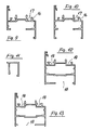
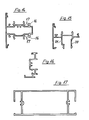
lug 3 is formed, a further orsecond lug 15 may be provided,of substantially cranck shape and effective to improve the coupling of said wing to the section. - In particular,in figs.9,10 and 14 there are respectively shown a section known as "open hung frame",a section known as "open flat frame".and a tie rod T section,which are characterized in that they are provided,at the locking seat of the closing or closure rod,a
longitudinal lug 16,of predetermined thickness,effective to provide a sure sealing on the end portion of said closing rod. - Moreover,the two lugs defining the locking seat are provided with
continuous slots 17 effective to operate as sliding guides for possible other fittings. - Fig.ll illustrates a glass stopping section and fig.12 illustrates a so-called Z-section,provided with a seat or slot,18,for a plate glass to be insertet thereinto.
- Fig.13 illustrates a T-section,provided with a glass receicing slot or seat offset towards the abutment side and including two sliding
seats 19 for the closing rod. - Fig.15 illustrates an insertion section, effective to be snap inserted by means of the two
legs - Moreover that insertion section,which -is used snap coupled to said Z-section,in order to make the central upright of two-wing frames, is effective to provide a perfect continuity of the open joint,since the
leg 21 recovers,both in the upper portion and in the lower portion, the continuity of the abutment surface of the gasket,without the need of using any plastics blocks or the like. - Fig.16,in turn, illustrates, at a turned through 90° position with respect to the horizontal, a section which may be used as a base crosspiece for French windows,whereas figure 17 illustrates a base or intermediate band section.
- The angled coupling of four portions of a base section,indicated generally at 22 in figure 20,for making a fixed frame of a wing,is obtained by using
σorresmponding bracket members 23. - Said bracket members comprise two angled
small plates vertical portion 24' and 25t whereof,and depending on their linear dimensions,with respectively one or more throughholes 26 and corresponding threaded holes 26',formed at given different levels on said two small plates. - The latter are sized depending on the sections to be coupled and have the base whereof of a predetermined greater width than the height of the chamber or hollow of the sections.
- The vertical portion of one of the two small plates,in particular,is provided,at the side end portions whereof,with recessed
portions 27 effective to house two side wings or legs 27' as formed on the other small plate. - The mentioned recessed portions are effective to define,in actual practice,
upper projections 28 andlower projections 29,which prevent the two small plates from being transversely mutually rotated. - Alternatively,in the case of shallow chamber sections,the mentioned
upper projections 28 may be omitted,due to space reasons. - In the base portions of said small plates, moreover, may be formed,at the side ends, semicircular cuts or
interruptions 30 effective to allow for the cremone rod to pass therethrough. - Said small plates are fixedly coupled to one another with the interposition of a
flexible blade 31,suitably shaped and dihedral bent,by means of a drawing ortraction screw 32 engaging in the mentionedholes 26 and 26'. - In actual practice,after having arranged the two small plates at the mouth of the sections to be coupled,the
screw 32 is screwed on by means of a suitable screwdriver through asingle hole 33 as formed on the outside of said sections. - Thus, the vertical portions 24' and 25' are caused to approach one another,with the consequent mutual rotation of the
bases corners 34,engage with the innner walls of the two sections. - By further screwing on said
screw 32, the two small plates are caused to rotate in such a way as to approach one another;however,due to the fact that said plates are restrained to the bases of the sections, they will be more and more restrained to the walls of said sections thereby forcibly causing the two faces of the sections to be coupled to adjoin one another. - In this connection it should be noted that the provision of the dihedral
resilient blade 31 interposed between the two small plates is effective to hold stable,in the absence of outside forces or stresses,the mutual position of said two small plates,thereby facilitating the insertion thereof into the two sections to be coupled. - Moreover,the mentioned resilient blade is sized in such a way that one of its upper edges is effective to be brought into contact with the corresponding wall of the chamber or hollow of the section,thereby restraining thereto said bracket member,during the approaching operation of its two portions.
- It should also be noted that the mentioned bracket member,owing to its specifically designed structure is also effective to be used for angle coupling other types of sections.
- The handle,designed for being automatically coupled on sections including in the section set according to the present invention, comprises a box-
like body 35,of substantially conventional configuration,therein there are housed theconventional gears 36 for driving thelegs 37 which,by engaging in correspondingseats 38, formed on the closing rods,cause said closing rods to be upwardly and downwardly displaced. - Inside the mentioned box-like body there are located,on the outside of the mentioned legs,two tabs or
tongues 39 provided with a cut 39' having a width equal to the thickness of theleg 40 of thegeneric upright 41 thereto the handle is to be applied. - The mentioned tabs,in particular, may be advantageously mounted on corresponding
blocks 42,having any suitable shapes and effective to be fixedly coupled to the box-like body35,in such a way as to be able of sliding therewithin. - Through the
leg 40 of the upright,or crosspiece,provided for locking the handle,there is formed,in addition to the two slots provided for the passage of thelegs 37,and having a suitable lenght in such a way as to permit also the passage of thetabs 39,anintermediate hole 43,effective to receive the end portion,as suitably extended, of thepin 44, coaxially extending with respect to thehandle 45. - In particular,as the box-
like body 35 is provided with two open ends, (figure 21),then the face 42' of theblock 42 acts as a closure element,on the two sides, and as a finishing element for said box-like body (figures 25 and 26). - In actual practice, by applying the box-
like body 35 on theleg 40 of the upright or crosspiece, in such a way that thelegs 37 andtabs 39 are inserted into theslots 41 and thepin 44 is inserted into thehole 43,in order to lock said handle on the leg it will be sufficient to cause the handle to rotate,as in the case therein the frame is normally closed. - By that operation, infact, the
gear 36 causes thelegs 37 to be outwardly displaced, said legs pushing the tabs against the edge of the slots until the tab cut 39' firmly engages on said edge. - It should moreover be pointed out that the mentioned handle may also be quickly and easily removed from the corresponding upright or cross- piece.
- To this end it will be sufficient to disengage the
tabs 39 from the edges of theslots 41, by acting from the outside-(in the case of a handle the body whereof is provided with open ends)-on theblocks 42 bearing said tabs. - In the case of a handle provided with a closed box-like body, on the other hand, there is provided a hole,at the two ends of said box-like body,therethrough it will be possible to operate said blocks.
- Moreover,said handle may be applied,by the procedure thereinabove illustrated, also on frames made starting from metal sections of any other types.
- Among the fittings cooperating with the disclosed section set there is included a
friction hinge 46,which is provided with alug 3,having a continuous orserrated projection 2,analogous to the above mentioned hinges of figures 2 and 5,effective to be snap locked in the corresponding section,for making hung windows. - A
like lug 3,provided with acontinuous projection 2,is formed on afurther fitting 47, forming a ratchet effective to be used for closing the so-called vasistas windows. - In particular it is advantageously provided that the bolt 47' of the mentioned ratchet is effective to be inserted,during the closing step, into the locking seat of the closing rod,as formed in the basic sections.
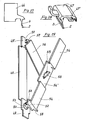
- The hinge coupling between the wing and frame of the mentioned windows,as well as the limiting of the opening whereof are advantageously obtained by using an articulated fitting,(figure 29), which may be easily assembled without requiring screws,pins or the like.
- That fitting, which is known as "vasistas compass" comprises a first elongated plate (48) effective to be slidingly housed in the upright of the fixed frame and provided with
end portions 49 and 49', of the cantilever type. - Through the
portion 49,provided for contacting the lower corner of the frame,there is formed a through hole ofoval shape 50,whereas on the other portion there is formed an intermediate slot or recess,5l. - In the mentioned through hole there is affixed, through an
orthogonal lug 52,provided with anend crosspiece 53,a second elongatedsmall plate 54 effective to be housed, also slidingly, in the upright of the wing and provided with ε recessed intermediate portion 54',therein a slot is formed, indicated at 55. - The coupling of the mentioned
plates small plate 56 provided,at the end portions whereof and on opposite sides,with an orthogonal lug 57,terminated by acrosspiece 58. - More specifically, in order to hold the lower crosspiece of the wing suitably spaced from the frame cross member,to allow for said wing to be properly rotated,the
small plate 54 is provided, at the lower end whereof,with twoside projections 59 effective to operate as abutment or stop members for the downwardly sliding of the upright of said wing. - Moreover,the weight of the wing,exerσed on the.
small plate 54 and accordingly on thesmall plate 48,is effective to hold the compass properly positioned in its seats,without the need of restraining the same by using screws and the like to the sections. - Thus the wing may be easily and quickly disengaged from the frame.
- From the above disclosure will be self- evident the great functionality and use facility characterizing the set of window or door frame sections and related fittings according to the present invention.
- While the subject set has been thereinabove illustrated and disclosed with reference to preferred embodiments whereof,it is to be noted that it is susceptible to several modifications and variations,all whereof fall within the spirit and scope of the invention,as defined in the accompanying claims.
Claims (16)
1 - A set of window or door frame sections and related fittings, charaterized in that said sections are provided with continuous longitudinal shapings or shaped portions effective to snap lock one or more lugs 3 provided with a projecting edge, as formed at one end of a leg, forming a portion of a hinge 46, of a clutch for a hung window and of a closure ratchet gear 47 for vasistas, cooperating, as fittings, with said sections, said fittings further comprising a bracket member 23 for assembling the frame and movable wings, a compass 48 for vasistas windows, of the reversible type (right and left), the structural members whereof are mutually coupled by a simple restrained joint -(without screws or pins)- and are slidingly coupled to the uprights of said frame and wing, and a handle 35 of the cremone type, including means effective to allow for said handle 35 to be automatically affixed on an upright or cross-member of said frame, the basic sections of said set being moreover provided with two shaped parallel longitudinal seats 1 effective to slidingly house the closure or closing rod and one of the end portions of said rod for locking it to the fixed frame.
2 - A set of window or door frame sections and related fittings according to the preceding claim, charaterized in that it comprises, among the basic sections whereof, at least a section provided with a longitudinal seat 1 formed at a given distance from the surface of said section and effective to lock one or more projecting teeth, or a continuous projection 2, as formed at the end portion of a lug 3 provided on the hinge, on the clutch for hung windows and on said closure or closing ratchet gear 47, wherein, for firmly coupling one of said fittings to the section a longitudinal slot is formed at a desidered position in the wall of said section, said longitudinal slot having such a lenght related to the width of said lug 3, said lug being provided, at the coupling portion whereof to said fitting, with a tapered portion 5.
3 - A set of window or door frame sections, according to claim 1, charaterized in that in the sliding seat 6 of said closing rod 8 there is arranged a sealing gasket 13, said sealing gasket 13 abutting on the edge of the seat 6 comprising the locking element or said closing rod 8 and delimitating the expansion chamber of said frame.
4 - A set of window or door frame sections, according to claim 1, charaterized in that it comprises an open wing frame, an open flat frame and a T-tie rod which are provided, at said closing rod 8 locking seat 6, with a longitudinal lug 16 of predetermined thickness effective to provide a sure sealing on the end portion of said closing rod 8, the two lugs defining said closing rod 8 locking seat 6 being further provided with continuously extending slots 17.
5 - A set of window or door frame sections, according to claim 1, charaterized in that it comprises a glass stopping or restraining section, a Z section provided with a slot for the glass plate to be inserted thereinto, a T-section provided with a slot for the glass plate offset towards the abutment side whereof and provided with two sliding seats for said closing rod 8, an insertion section effective to be snap inserted by means of two wings, a section effective to be used as a base cross-member for a French window and a base or intermediate band section.
6 - A set of fittings effective to cooperate with the window or door frame section according to claim 1, charaterized in that the assembling bracket member comprises two small angled plates 24, 25 provided, at the vertical portion whereof 24', 25' and depending on their linear dimensions, with respectively one or more through holes 26 and corresponding said plates 24', 25',/ threaded holes 26', formed at different levels through/sald plates being sized depending on the sections to be coupled and having the base whereof of a width greater than the height of the chamber or hollow of said sections, the vertical portion of one of said plates being provided, at the side end portions whereof, with recessed portions 27 effective to house two side wings 27' or legs as formed on the other plate, said recessed portions 27 defining upper 28 and lower 29 projections effective to prevent said plates 24, 25 from mutually transversely rotating.
7 - A set of fitting according to claim 6, charaterized in that, in the case of sections with shallow chambers or hollows, said upper projections 28 are lacking and in that, in the base portions of said plates 24, 25, there are formed side semicircular interruptions 30 or cuts effective to allow for said closing rod to pass through.
8 - A bracket member, according to claim 6, charaterized in that said small plates 24, 25 are coupled to one another with the interposition of a shaped and dihedral bent flexible blade 31, by means of a drawing screw 32 engaging in the holes 26, 26' formed in the vertical portions of said plates 24, 25, said dihedral resilient blade 31 being effective to hold stable, in the absence of external forces, the mutual position of said plates 24, and being so sized that one of its top edge is able of contacting the corresponding wall of the section hollow, thereby affixing thereto said bracket member during the approaching of the two portions.
9 - A handle, according to claim-1, charaterized in that it comprises a box-like body 35, of conventional shape, therein there are housed the conventional gear 36, for operating the handle legs 37 which, by engaging with corresponding seats 38 formed in the closing rods, cause said rods to move in one direction or in the opposite direction, in the inside of said box-like body 35 there being arranged, outside of side legs 37, two tabs 39 provided with a cut 39' having a widht equal to the thickness-of the wing 40 of the upright 41 or a cross-member thereon said handle is to be applied, said tabs being mounted on shaped blocks 42 effective to be fixedly coupled to said box-like body 35, in such a way as to be able of sliding within said box-like body 35.
10 - A handle according to the preceding claim, charaterized in that it is provided with a central pin 44 effective to be inserted into a hole 43 formed on said upright or cross-member 41, jointly to the slots 40 provided for the passage of said legs 37 and at an intermediate position with respect to said slots 40.
11 - A handle according to claim 9, charaterized in that it is effective to be applied on window or door frames made starting from sections of any types.
12- A friction hinge 46 according to claim 1, charaterized in that it is provided with a lug 3 on the edge whereof there is formed a projectingportion 2, either of the continuous or serrated type, effective to be snap locked in corresponding recessed portions formed in the sections of said set,- for making hung windows.
13 - A ratchet 47 effective to be used for closing vasistas windows according to claim 1, charaterized in that the bolt 47' of said ratchet 47 is effective to be inserted, during the closing step, into the locking seat of the sliding rod, as formed in the basic sections of said set.
14 - A compass for vasistas windows, according to claim 1, charaterized in that it is so designed and arranged as to afford the possibility of hinge coupling the frame and wing of said windows, as weel as limiting the opening stroke of the windows, and in that it consists of an articulated structure effective to be assembled without using screws, pins and the like elements, said structure comprising a first elongated small plate 48 provided for being housed slidingly in the upright of the fixed frame and provided with cantilever end portions 49, 49', a oval through hole 50 being formed in that cantilever portion 49 to be contacted with the lower corner of said frame and an intermediate recessed portion 51 being formed in the other cantilever portion 49'.
15 - A compass for vasistas windows according to claim 14, charaterized in that in said through hole 50 there is restrained, by means on a lug 52 provided with an end cross-piece 53, a second elongated small plate 54 effective to be slidingly housed in the upright of the window wing and including an intermediate recessed portion 54' therein a slot 55 is formed, the coupling between said small plates 48, 54 and hence between said window frame and wing being obtained through a third small plate 56 provided, at the end portions whereof and on opposite sides, with a perpendicular lug 57 ending with a cross piece 58.
16 - A compass fos vasistas windows, according to claim 14, charaterized in that, in order to hold the wing lower cross piece at a predetermined distance from the frame cross-member to allow for said wing to properly rotate, said second small plate 54 is provided, at the lower and portion whereof, with two side projections 59 effective to operate as stop members for the downwardly directed sliding of said upright of said wing.
Applications Claiming Priority (2)
| Application Number | Priority Date | Filing Date | Title |
|---|---|---|---|
| IT21618/83A IT1169732B (en) | 1983-06-14 | 1983-06-14 | SERIES OF PROFILES FOR WINDOWS AND RELATED ASSEMBLY AND / OR FUNCTIONAL ACCESSORIES, COUPLED WITH THE SAME PROFILES THROUGH A JOINT AND / OR SLIDING OPERATION |
| IT2161883 | 1983-06-14 |
Publications (2)
| Publication Number | Publication Date |
|---|---|
| EP0128259A2 true EP0128259A2 (en) | 1984-12-19 |
| EP0128259A3 EP0128259A3 (en) | 1986-07-02 |
Family
ID=11184398
Family Applications (1)
| Application Number | Title | Priority Date | Filing Date |
|---|---|---|---|
| EP83830180A Withdrawn EP0128259A3 (en) | 1983-06-14 | 1983-09-20 | Set of window or door frame sections and related cooperating fittings |
Country Status (2)
| Country | Link |
|---|---|
| EP (1) | EP0128259A3 (en) |
| IT (1) | IT1169732B (en) |
Cited By (8)
| Publication number | Priority date | Publication date | Assignee | Title |
|---|---|---|---|---|
| GB2196367A (en) * | 1986-09-02 | 1988-04-27 | Bowater Ind Public Limited Com | Improvements in extrusion profiles |
| EP0387204A3 (en) * | 1989-03-09 | 1990-12-19 | Metra Metallurgica Trafilati Alluminio S.P.A. | Section member system for making window and door frames |
| GB2290335A (en) * | 1994-05-26 | 1995-12-20 | Stoves Ltd | Cantilever mounted oven door |
| EP0913546A2 (en) * | 1997-10-31 | 1999-05-06 | ROTO FRANK Aktiengesellschaft | Fitting for an actuating mechanism of a door or window wing |
| US5901509A (en) * | 1995-11-17 | 1999-05-11 | Rose; John Edward | Component for a window frame |
| GB2408283A (en) * | 2003-10-17 | 2005-05-25 | Bowater Building Prod | Window frame for different forms of glazing bead |
| CN109236117A (en) * | 2017-07-11 | 2019-01-18 | 冯志平 | A kind of doorframe and the rotation door using the doorframe |
| GB2525183B (en) * | 2014-04-14 | 2021-01-13 | Storm Faith Network Ltd | Fenestration products |
Citations (3)
| Publication number | Priority date | Publication date | Assignee | Title |
|---|---|---|---|---|
| FR2066212A5 (en) * | 1969-10-21 | 1971-08-06 | Vmw Ranshofen Berndorf Ag | |
| FR2438189A1 (en) * | 1978-10-06 | 1980-04-30 | Mascioletti Ascanio | SUPPORT BRACKET FOR THE ASSEMBLY, AT A RIGHT ANGLE, OF TWO TUBULAR PROFILES FOR THE MANUFACTURE OF FRAMES OR THE LIKE |
| EP0049694A1 (en) * | 1980-10-08 | 1982-04-14 | SLIM Società Lavorazioni Industriali Metalli S.p.A. | A set of metal sections for constructing door and window support frames |
-
1983
- 1983-06-14 IT IT21618/83A patent/IT1169732B/en active
- 1983-09-20 EP EP83830180A patent/EP0128259A3/en not_active Withdrawn
Patent Citations (3)
| Publication number | Priority date | Publication date | Assignee | Title |
|---|---|---|---|---|
| FR2066212A5 (en) * | 1969-10-21 | 1971-08-06 | Vmw Ranshofen Berndorf Ag | |
| FR2438189A1 (en) * | 1978-10-06 | 1980-04-30 | Mascioletti Ascanio | SUPPORT BRACKET FOR THE ASSEMBLY, AT A RIGHT ANGLE, OF TWO TUBULAR PROFILES FOR THE MANUFACTURE OF FRAMES OR THE LIKE |
| EP0049694A1 (en) * | 1980-10-08 | 1982-04-14 | SLIM Società Lavorazioni Industriali Metalli S.p.A. | A set of metal sections for constructing door and window support frames |
Cited By (11)
| Publication number | Priority date | Publication date | Assignee | Title |
|---|---|---|---|---|
| GB2196367A (en) * | 1986-09-02 | 1988-04-27 | Bowater Ind Public Limited Com | Improvements in extrusion profiles |
| EP0387204A3 (en) * | 1989-03-09 | 1990-12-19 | Metra Metallurgica Trafilati Alluminio S.P.A. | Section member system for making window and door frames |
| GB2290335A (en) * | 1994-05-26 | 1995-12-20 | Stoves Ltd | Cantilever mounted oven door |
| GB2290335B (en) * | 1994-05-26 | 1997-10-22 | Stoves Ltd | Improvements in or relating to doors |
| US5901509A (en) * | 1995-11-17 | 1999-05-11 | Rose; John Edward | Component for a window frame |
| EP0913546A2 (en) * | 1997-10-31 | 1999-05-06 | ROTO FRANK Aktiengesellschaft | Fitting for an actuating mechanism of a door or window wing |
| EP0913546A3 (en) * | 1997-10-31 | 2003-01-22 | ROTO FRANK Aktiengesellschaft | Fitting for an actuating mechanism of a door or window wing |
| GB2408283A (en) * | 2003-10-17 | 2005-05-25 | Bowater Building Prod | Window frame for different forms of glazing bead |
| GB2408283B (en) * | 2003-10-17 | 2005-10-12 | Bowater Building Prod | Window and door assemblies |
| GB2525183B (en) * | 2014-04-14 | 2021-01-13 | Storm Faith Network Ltd | Fenestration products |
| CN109236117A (en) * | 2017-07-11 | 2019-01-18 | 冯志平 | A kind of doorframe and the rotation door using the doorframe |
Also Published As
| Publication number | Publication date |
|---|---|
| IT1169732B (en) | 1987-06-03 |
| EP0128259A3 (en) | 1986-07-02 |
| IT8321618A0 (en) | 1983-06-14 |
Similar Documents
| Publication | Publication Date | Title |
|---|---|---|
| US4578903A (en) | Corner locking and associated pivot means for extruded plastic sash windows | |
| EP0428589B1 (en) | Connection system | |
| EP0049694B1 (en) | A set of metal sections for constructing door and window support frames | |
| US4622778A (en) | Latch and corner support for pivotal window sash | |
| US6311454B1 (en) | Door construction | |
| US3889423A (en) | Reversible door frame | |
| EP0128259A2 (en) | Set of window or door frame sections and related cooperating fittings | |
| GB2037352A (en) | Hanger for a folding door | |
| US3464157A (en) | Window construction | |
| EP0233021B1 (en) | Pivot block for bifold doors | |
| US5317853A (en) | Expansion joint and spheres therefor | |
| US4887407A (en) | Alignment clip member for windows and associated method | |
| US2836269A (en) | Metallic door and hinge assembly | |
| US4087941A (en) | Window assembly | |
| KR100698839B1 (en) | The coupling structure between door and side of wall for GMP facilities | |
| US3472543A (en) | Method and structure for tightening secured matched abutting tubular stiles and rails by the contraction of the joined tubular members on a gusset | |
| JP3177910B2 (en) | Window frame made of synthetic resin | |
| US20020112420A1 (en) | Multi-use door-frame structure | |
| JPS6016228Y2 (en) | window sealing device | |
| JPS641419Y2 (en) | ||
| US4047333A (en) | Snap-in keeper for sliding windows, doors and the like | |
| JP2565101Y2 (en) | Auxiliary lock for sliding door | |
| JPH0128214Y2 (en) | ||
| JPH0439978Y2 (en) | ||
| US3040850A (en) | Window |
Legal Events
| Date | Code | Title | Description |
|---|---|---|---|
| PUAI | Public reference made under article 153(3) epc to a published international application that has entered the european phase |
Free format text: ORIGINAL CODE: 0009012 |
|
| AK | Designated contracting states |
Designated state(s): AT BE CH DE FR GB LI NL SE |
|
| 17P | Request for examination filed |
Effective date: 19850605 |
|
| PUAL | Search report despatched |
Free format text: ORIGINAL CODE: 0009013 |
|
| AK | Designated contracting states |
Kind code of ref document: A3 Designated state(s): AT BE CH DE FR GB LI NL SE |
|
| STAA | Information on the status of an ep patent application or granted ep patent |
Free format text: STATUS: THE APPLICATION IS DEEMED TO BE WITHDRAWN |
|
| 18D | Application deemed to be withdrawn |
Effective date: 19880331 |