EP0128246A1 - Implement for cutting fodder or a similar crop, especially a silage cutter - Google Patents
Implement for cutting fodder or a similar crop, especially a silage cutter Download PDFInfo
- Publication number
- EP0128246A1 EP0128246A1 EP83200867A EP83200867A EP0128246A1 EP 0128246 A1 EP0128246 A1 EP 0128246A1 EP 83200867 A EP83200867 A EP 83200867A EP 83200867 A EP83200867 A EP 83200867A EP 0128246 A1 EP0128246 A1 EP 0128246A1
- Authority
- EP
- European Patent Office
- Prior art keywords
- support member
- cutting device
- knife
- support
- silage cutter
- Prior art date
- Legal status (The legal status is an assumption and is not a legal conclusion. Google has not performed a legal analysis and makes no representation as to the accuracy of the status listed.)
- Withdrawn
Links
Images


Classifications
-
- B—PERFORMING OPERATIONS; TRANSPORTING
- B26—HAND CUTTING TOOLS; CUTTING; SEVERING
- B26D—CUTTING; DETAILS COMMON TO MACHINES FOR PERFORATING, PUNCHING, CUTTING-OUT, STAMPING-OUT OR SEVERING
- B26D7/00—Details of apparatus for cutting, cutting-out, stamping-out, punching, perforating, or severing by means other than cutting
- B26D7/01—Means for holding or positioning work
-
- A—HUMAN NECESSITIES
- A01—AGRICULTURE; FORESTRY; ANIMAL HUSBANDRY; HUNTING; TRAPPING; FISHING
- A01F—PROCESSING OF HARVESTED PRODUCE; HAY OR STRAW PRESSES; DEVICES FOR STORING AGRICULTURAL OR HORTICULTURAL PRODUCE
- A01F25/00—Storing agricultural or horticultural produce; Hanging-up harvested fruit
- A01F25/16—Arrangements in forage silos
- A01F25/20—Unloading arrangements
- A01F25/2027—Unloading arrangements for trench silos
- A01F25/2036—Cutting or handling arrangements for silage blocks
Definitions
- Cutting device for cutting cattle fodder or the like crop, as well as silage cutter, or other agricultural device, carried out with such a cutting device.
- the invention relates to a cutting device for cutting cattle fodder or the like, provided with an upward and downward movable, plate - shaped support member with a support surface which supports at least one plate - shaped knife member designed with teeth, which teeth of the knife member are at least approximately horizontal or can act vertically moving on the crop, as well as on a silage cutter or other agricultural device, carried out with such a cutting device.
- the invention aims to provide a cutting device of the type mentioned in the beginning, in which this disadvantage is overcome in a simple but nevertheless expedient manner.
- the cutting device according to the invention is characterized in that the side of the knife element facing away from the support element encloses an acute angle with the vertical such that the knife element is pressed against the support element by the crop during the downward movement of the support element.
- At least the part of the support element comprising the support surface encloses an acute angle with the vertical.
- the support surface of the support member can be chamfered in the downward direction.
- the support member can be L-shaped or U-shaped with two or three support surfaces, each of which supports a knife member, which knife members together have an L-shaped or U-shaped course, the adjacent ends of the successive knife organs are coupled together by a flexible truncated organ.
- the cutting device is characterized in that the successive straight parts of the support element merge into one another via a curve part, a guide plate for the relevant coupling element in each curve part and the adjoining ends of the straight parts of the support element at the level of the relevant coupling element is arranged.
- a discharge opening is formed in the support member. It is hereby achieved that crop that comes in the corner or the corners of the support member between the knife members and the support member is immediately removed again through the discharge openings formed in the support member.
- the invention further relates to a silage cutter, provided with a frame which can be fastened to a tractor and comprises an upstanding frame part, while a number of parallel carrying tines are fastened to an at least approximately horizontal crossbar.
- This silage cutter is characterized in that it is designed with a cutting device according to the invention.
- the invention relates to an agricultural implement, which is characterized by a cutting device according to the invention.
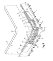
- a perspective view of a silage cutter 1 is shown, which is provided with a cutting device 2 for cutting cattle feed or the like.
- the cutting device 2 is provided with a U-shaped support member 3, which is formed from a sheet metal bent into the desired U-shape.
- the legs of the U-shaped support member 3 enclose an obtuse angle with the web of the support member 3.
- the support member 3 is movable up and down to cut a block of silage from a silage supply, as will be described in more detail below.
- the legs and the web of the support member 3 are each provided with a support surface 4 which, as shown in FIG. 2, supports a plate-shaped knife member 6 with teeth 5.
- the three knife members 6 are adjustable back and forth relative to the support member 3.
- the support member 3 has retaining teeth 7 which protrude downwards relative to the teeth 5 of the knife members 6 and at the same time can act on the crop to be cut with the teeth 5 of the knife members 6. A particularly expedient cutting action of the cutting device 2 is thereby achieved.
- each support surface 4 of the support member 3 is chamfered in the direction of the retaining teeth 7, the angle which the plane of the support surface 4 includes with the plane of the remaining part of the support member 3 is preferably at least 2 ° that the side of the knife elements facing away from the support element 3 encloses an angle of at least 3 ° with the vertical.
- the adjacent ends of the successive knife elements 6 are coupled to one another by a chain 9.
- another flexible coupling element such as a band or the like, can be used.
- a slot 11 is arranged at the level of the chain 9.
- a curved guide plate 12 is attached, which closes the slot 11 for the most part.
- the guide plate 12 carries a bronze guide plate 13 which projects into the slot 11 in question and guides the associated chain 9.
- the chains 9 are therefore somewhat recessed in the slot 11, so that the entrainment of the crop during the reciprocating movement of the knife members 6 is limited to a minimum.
- the bronze guide plate 13 ensures that the heat generated during the movement is rapidly dissipated.
- Each chain consists of a number of links 16, which links 16 are each provided with rounded recesses 17.
- the radius of curvature of these recesses 17 is at least approximately equal to that of the associated one Curve part 10 of the support member 3, so that the links 16 closely connect to the bronze guide plate 13.
- Each chain 9 is further coupled by means of two coupling pieces 18 to the adjacent ends of the associated knife elements 6.
- the dome pieces 18 are attached to the relevant ends of the knife elements 6.
- Each coupling piece 18 has a fork-shaped end 19, the teeth 20 of which run at least approximately horizontally and are connected to the associated end link 16 of the chain 9. Furthermore, the end 19 protrudes into the associated slot 11.
- the silage cutter 1 shown in FIG. 1 and executed with the cutting device 2 is provided with a frame 21 which is designed with attachment points 22 for coupling the silage cutter 1 to the lifting device of a tractor.
- the frame 21 comprises an upright frame part 23 with a horizontal crossbeam 24 at the lower end, to which a number of parallel carrying tines 25 are fastened.
- the U-shaped support member 3 of the cutting device 2 is provided at both ends with supports 26 (see FIGS. 2 and 4), in each of which two wheels 27 are rotatably mounted.
- the support member 3 is guided with the wheels 27 at least approximately in the vertical direction in two C-profiles 28 of the upstanding frame part 23.
- the open sides of the C-profiles 28 are turned away from each other.
- the wheels 27 exert large forces on the C-profiles 28 of the upstanding frame part 23.
- the wheels 27 have a rounded running surface 29, the radius of curvature of the running surface 29 being greater than the radius of curvature of the bent parts 30 of the C-profiles 28.
- each C-profile 28 is carried out at the free ends of the parts 30 with a straight extension 31, which improves the strength of the C-profile 28.
- the upward and downward movement of the U-shaped support member 3 is effected by means of adjustment members carried by the frame 21.
- these adjusting members consist of an upright cylinder-piston unit 32 supported by the frame 21, the piston rod 33 of which carries a disk block 34.
- the support member is upward and adjustable downwards.
- the three knife elements 6, which are coupled to one another by the chains 9, can be adjusted back and forth in the cutting device 2 relative to the support element 3 by means of two cylinder-piston units 37, the piston rods 38 of which at the relevant free ends of those on the legs of the support element 3 located knife organs 6 are attached.
- the cylinder-piston units 37 are supported by the support member 3.
- These cylinder-piston units 37 are double-acting in the exemplary embodiment shown in FIG. 1 and are actuated via a hydraulic changeover valve and check valves in such a way that the piston rods 38 are always adjusted in the opposite direction, as a result of which the knife members 6 receive the desired reciprocating movement.
- the two double-acting cylinder-piston units 37 are also hydraulically coupled to the upright cylinder-piston unit 32, the support member 3 being adjusted step by step, each step coinciding, for example, with a reciprocating movement of the knife members 6.
- Supports 39 for the knife members 6 are arranged on the legs and the web of the U-shaped support member 3, the upper edge of the knife members 6 being adjustable back and forth along the supports. Support the supports 39 downwardly projecting sealing lips 40, as a result of which the knife elements 6 are held in position in cooperation with the connection of the ends of the knife elements to the piston rods 38 of the cylinder-piston units 37 and the coupling pieces 18 guided with their ends 19 in the slots 11.
- the knife members 6 are each only attached at the ends to the support member 3, so that the knife members 6 can be loosened simply by removing the connecting pins 41 which effect the connection to the chains 9 and which are connected by a coupling pin (not shown in the drawing) effected connection with the piston rods 38 is interrupted.
- each connecting pin 41 lies in an at least approximately vertical plane in which the extension of the upper side of the relevant knife element 6 also lies at least approximately.
- the support member 3 is provided at the free ends with supports 42 which protrude downwards relative to the knife members 6 and the retaining teeth 7 of the support member 3 (see FIG. 2).
- the support member 3 is adjustable with the teeth of the knife members 6 beyond the support tines 25 of the frame 21.
- the supports 42 lie on the ground at the end of the cutting cycle, so that the carrying tines 25 are raised somewhat upwards and the cut-out block of silage material is completely released from the silage material supply.
- the U-shaped support member 3 extends obliquely downwards from the upright frame part 23 in the rest position, an angle of approximately 1 ° being included with the horizontal plane. As a result, the support member 3 will be approximately horizontal during operation.
- the invention is not limited to the exemplary embodiment described above, which can be modified in various ways in the context of the invention. For example, it is also possible to equip other agricultural implements for animal feed plants with a cutting device according to the invention.
- the cutting device can also be designed with an L-shaped support member which interacts with two knife members. For certain applications, too a supporting element which has just been executed and which interacts with a knife element is sufficient.
- each support surface of the support member can also cooperate with two knife members, in which case the retaining teeth can be omitted if necessary.
- the knife elements can also be designed to be movable in the vertical direction instead of in the horizontal direction.
- another sliding element can also be used, for example made of plastic.
Abstract
Description
Schneidvorrichtung zum Schneiden von Viehfutter oder dergleichem Gewächs,sowie Silagegutschneider, oder sonstiges landwirtschaftliches Gerät, ausgeführt mit einer dergleichen Schneidvorrichtung.Cutting device for cutting cattle fodder or the like crop, as well as silage cutter, or other agricultural device, carried out with such a cutting device.
Die Erfindung bezieht sich auf eine Schneidvorrichtung zum Schneiden von Viehfutter oder dergleichem Gewächs, versehen mit einem aufwärts und abwärts beweglichen, platten - förmigen Tragorgan mit einer Stützfläche, die wenigstens ein mit Zähnen ausgeführtes, plattenförmiges Messerorgan unterstützt, welche Zähne des Messerorganes wenigstens angenähert horizontal oder vertikal bewegend auf das Gewächs einwirken können, sowie auf einen Silagegutschneider oder ein sonstiges landwirtschaftliches Gerät, ausgeführt mit einer dergleichen Schneidvorrichtung.The invention relates to a cutting device for cutting cattle fodder or the like, provided with an upward and downward movable, plate - shaped support member with a support surface which supports at least one plate - shaped knife member designed with teeth, which teeth of the knife member are at least approximately horizontal or can act vertically moving on the crop, as well as on a silage cutter or other agricultural device, carried out with such a cutting device.
Bei Versuchen mit einem Silagegutschneider, versehen mit einer dergleichen Schneidvorrichtung, hat sich herausgestellt, dass die Schneidwirkung unter Umständen stark abnehmen kann und sogar ganz verlorengehen kann, indem sich zwischen dem Tragorgan und dem Messerorgan Gewächs anhäuft.In experiments with a silage cutter equipped with such a cutting device, it has been found that the cutting effect can, under certain circumstances, decrease significantly and can even be lost entirely, as crops accumulate between the support member and the knife member.
Die Erfindung bezweckt eine Schneidvorrichtung der im Anfang genannten Art zu schaffen, bei welcher dieser Nachteil in einfacher, jedoch nichtsdestoweniger zweckmässiger Weise beseitigt ist.The invention aims to provide a cutting device of the type mentioned in the beginning, in which this disadvantage is overcome in a simple but nevertheless expedient manner.
Zu diesem Zweck ist die Schneidvorrichtung nach der Erfindung dadurch gekennzeichnet, dass die vom Tragorgan abgekehrte Seite des Messerorganes einen spitzen Winkel mit der Vertikalen einschliesst, derart, dass bei der abwärtsen Bewegung des Tragorganes das Messerorgan durch das Gewächs gegen das Tragorgan gedrückt wird.For this purpose, the cutting device according to the invention is characterized in that the side of the knife element facing away from the support element encloses an acute angle with the vertical such that the knife element is pressed against the support element by the crop during the downward movement of the support element.
In dieser Weise wird erreicht, dass die bei der abwärtsen Bewegung des Tragorganes während des Schneidens durch das Gewächs auf das Messerorgan ausgeübten Kräfte eine Komponente aufweisen, die das Messerorgan gegen das Tragorgan klemmt, sodass kein Gewächs zwischen das Messerorgan und das Tragorgan gelangen kann und die Schneidwirkung unter allen Umständen optimal bleibt.In this way it is achieved that the forces exerted on the knife member during the downward movement of the support member during cutting by the crop have a component that clamps the cutter member against the support member, so that no crop can get between the knife member and the support member and the Cutting effect remains optimal under all circumstances.
Nach einer einfachen Ausführungsform der Erfindung schliesst wenigstens der die Stützfläche umfassende Teil des Tragorganes einen spitzen Winkel mit der Vertikalen ein.According to a simple embodiment of the invention, at least the part of the support element comprising the support surface encloses an acute angle with the vertical.
Nach der Erfindung kann die Stützfläche des Tragorganes in abwärtser Richtung abgeschrägt sein.According to the invention, the support surface of the support member can be chamfered in the downward direction.
Bei der Schneidvorrichtung der im Anfang genannten Art kann das Tragorgan L- oder U-förmig mit zwei bzw. drei Stützflächen sein, die je ein Messerorgan unterstützen, welche Messerorgane zusammen einen L- bzw. U-förmigen Verlauf aufweisen, wobei die benachbarten Enden der aufeinanderfolgenden Messerorgane durch ein biegsames Küppelorgan miteinander gekuppelt sind.In the cutting device of the type mentioned in the beginning, the support member can be L-shaped or U-shaped with two or three support surfaces, each of which supports a knife member, which knife members together have an L-shaped or U-shaped course, the adjacent ends of the successive knife organs are coupled together by a flexible truncated organ.
Nach einer günstigen Ausführungsform der Erfindung wird die Schneidvorrichtung dadurch gekennzeichnet, dass die aufeinanderfolgenden geraden Teile des Tragorganes über einen Kurventeil in einander übergehen, wobei in jedem Kurventeil und den anschliessenden Enden der geraden Teile des Tragorganes in Höhe des betreffenden Kuppelorganes eine Führungsplatte für das betreffende Kuppelorgan angeordnet ist.According to a favorable embodiment of the invention, the cutting device is characterized in that the successive straight parts of the support element merge into one another via a curve part, a guide plate for the relevant coupling element in each curve part and the adjoining ends of the straight parts of the support element at the level of the relevant coupling element is arranged.
In der Ecke oder den Ecken des Tragorganes wird das Gewächs am leichtsten zwischen die Messerorgane und das Tragorgan gelangen, wodurch die oben bereits genannten Probleme auftreten können.In the corner or the corners of the support member, the crop is easiest to get between the knife members and the support member, which can cause the problems already mentioned above.
Nach einer günstigen Ausführungsform der Erfindung ist eine Abführungsöffnung im Tragorgan gebildet. Hierdurch wird erreicht, dass Gewächs, das in der Ecke oder den Ecken des Tragorganes zwischen die Messerorgane und das Tragorgan gelangt, sofort wieder über die im Tragorgan gebildeten Abführungsöffnungen abgeführt wird.According to a favorable embodiment of the invention, a discharge opening is formed in the support member. It is hereby achieved that crop that comes in the corner or the corners of the support member between the knife members and the support member is immediately removed again through the discharge openings formed in the support member.
Die Erfindung betrifft weiterhin einen Silagegut- Schneider, versehen mit einem Gestell, das an einem Schlepper befestigbar ist und einen aufstehenden Gestellteil umfasst, während an einem wenigstens angenähert horizontalen Querbalken eine Anzahl von parallelen Tragezinken befestigt ist. Dieser Silagegutschneider ist dadurch gekennzeichnet, dass dieser mit einer Schneidvorrichtung nach der Erfindung ausgeführt ist.The invention further relates to a silage cutter, provided with a frame which can be fastened to a tractor and comprises an upstanding frame part, while a number of parallel carrying tines are fastened to an at least approximately horizontal crossbar. This silage cutter is characterized in that it is designed with a cutting device according to the invention.
Schliesslich betrifft die Erfindung ein landwirtschaftliches Gerät, das durch eine Schneidvorrichtung nach der Erfindung gekennzeichnet ist.Finally, the invention relates to an agricultural implement, which is characterized by a cutting device according to the invention.
Die Erfindung wird hiernach weiter an Hand der Zeichnung erläutert.
- Fig. 1 ist eine perspektivische Ansicht eines Silagegutschneiders, der mit einer Ausführungsform der Schneidvorrichtung nach der Erfindung ausgeführt ist.
- Fig. 2 is ein Schnitt der Schneidvorrichtung des Silagegutschneiders aus Fig. 1 nach der Linie II-II.
- Fig. 3 ist eine perspektivische Ansicht eines Eckteiles der Schneidvorrichtung aus Fig. 1 in grösserem Masstab.
- Fig. 4 ist ein teilweise dargestellter Schnitt des Silagegutschneiders aus Fig. 1 nach der Ebene IV-IV.
- Fig. 1 is a perspective view of a Silage cutter which is designed with an embodiment of the cutting device according to the invention.
- Fig. 2 is a section of the cutting device of the silage cutter from Fig. 1 along the line II-II.
- Fig. 3 is a perspective view of a corner part of the cutting device of Fig. 1 on a larger scale.
- Fig. 4 is a partially shown section of the silage cutter from Fig. 1 according to the plane IV-IV.
In Fig. 1 ist eine perspektivische Ansicht eines Silagegutschneiders 1 dargestellt, der mit einer Schneidvorrichtung 2 zum Schneiden von Viehfutter oder dergleichem Gewächs versehen ist. Beim dargestellten Ausführungsbeispiel ist die Schneidvorrichtung 2 mit einem U-förmigen Tragorgan 3 versehen, das aus einem zur gewünschten U-Form gebogenen Blech gebildet ist. Die Schenkel des U-förmigen Tragorganes 3 schliessen dabei einen stumpfen Winkel mit dem Steg des Tragorganes 3 ein. Das Tragorgan 3 ist zum Ausschneiden eines Silagegutblockes aus einem Silagegutvorrat aufwärts und abwärts beweglich, wie weiterhin noch näher beschrieben werden wird.In Fig. 1 a perspective view of a silage cutter 1 is shown, which is provided with a cutting device 2 for cutting cattle feed or the like. In the illustrated embodiment, the cutting device 2 is provided with a U-shaped
Die Schenkel und der Steg des Tragorganes 3 sind je mit einer Stützfläche 4 versehen, die, wie in Fig. 2 dargestellt ist, ein mit Zähnen 5 ausgeführtes, plattenförmiges Messerorgan 6 unterstützt. Die drei Messerorgane 6 sind relativ zum Tragorgan 3 hin und her verstellbar. Das Tragorgan 3 besitzt Festhaltezähne 7, die relativ zu den Zähnen 5 der Messerorgane 6 abwärts ausragen und gleichzeitig mit den Zähnen 5 der Messerorgane 6 auf das zuschneidende Gewächs einwirken können. Dadurch wird eine besonders zweckmässige Schneidwirkung der Schneidvorrichtung 2 erzielt.The legs and the web of the
Die Schenkel und der Steg des U-förmigen Tragorganes 3 schliessen einen spitzen Winkel mit der Vertikalen ein, wie in Fig. 2 für den einen Schenkel dargestellt ist. Dieser Winkel beträgt vorzugsweise wenigstens 1°.Weiterhin ist jede Stützfläche 4 des Tragorganes3 in Richtung der Festhaltezähne 7 abgeschrägt, wobei der Winkel, den die Ebene der Stützfläche 4 mit der Ebene des übrigen Teiles des Tragorganes 3 einschliesst, vorzugsweise wenigstens 2° beträgt, so dass die vom Tragorgan 3 abgekehrte Seite der Messerorgane einen Winkel von wenigstens 3° mit der Vertikalen einschliesst. In dieser Weise wird erzielt, dass die Kräfte,die bei der abwärtsen Bewegung des Tragorganes 3 durch das Gewächs auf die Messerorgane6 ausgeübt werden, eine Komponente aufweisen, welche die Messerorgane 6 auf die Stützflächen 4 des Tragorganes 3 drücken. Dadurch wird verhindert, das Gewächs zwischen die Messerorgane 6 und das Tragorgan 3 gelangen kann. Gleichfalls wird durch die schräg nach aussen verlaufende Innenseite 8 der Schenkel und des Steges des Tragorganes 3 erzielt, dass beim Aufwärtsbewegen des Tragorganes 3 die Wände des ausgeschnittenen SilagegutBlockes kaum abbröckeln, so dass kein Silagegut verloren geht.The legs and the web of the U-shaped
Wie aus den Fig. 1 und 3 hervorgeht, sind die benachbarten Enden der aufeinanderfolgenden Messerorgane 6 durch eine Kette 9 miteinander gekuppelt. Erwünschtenfalls kann ein anderes biegsames Kuppelorgan angewandt werden, wie ein Band oder dergleiche. In den Kurventeile 10 und den anschliessenden Enden der Schenkel und des Steges des Tragorganes 3 ist in Höhe der Kette 9 ein Schlitz 11 angeordnet. Auf der Innenseite 8 des Tragorganes 3 ist an der Stelle jedes Schlitzes 11 eine gekrümmte Führungsplatte 12 befestigt, die den Schlitz 11 zum grössten Teil abschliesst. Die Führungsplatte 12 trägt eine bronzene Leitplatte 13, die in den betreffenden Schlitz 11 hineinragt und die zugehörige Kette 9 führt. Die Ketten 9 liegen dadurch einigermassen versenkt im Schlitz 11, wodurch das Mitreissen des Gewächses bei der hin und her gehenden Bewegung der Messerorgane 6 auf ein Minimum beschränkt ist. Weiterhin trägt die bronzene Leitplatte 13 Sorge für eine schnelle Abfuhr der während der Bewegung erzeugten Wärme.As can be seen from FIGS. 1 and 3, the adjacent ends of the successive knife elements 6 are coupled to one another by a chain 9. If desired, another flexible coupling element, such as a band or the like, can be used. In the
Zwischen den Enden der Führungsplatte 12 und den Enden des Schlitzes 11 liegen Abführungsöffnungen 14, wobei die an den Schlitz 11 anschliessenden Teile des Tragorganes 3 abgeschrägt sind, wie bei 15 dargestellt ist.Dadurch kann Gewächs, das in den Ecken des Tragorganes möglicherweise noch zwischen die Messerorgane 6 und das Tragorgan 3 gelangt, schnell abgeführt werden, so dass dieses keinen nachteiligen Einfluss auf die Schneidwirkung der Schneidvorrichtung 2 ausüben kann.There are
Jede Kette besteht aus einer Anzahl von Gliedern 16, welche Glieder 16 je mit abgerundeten Ausnehmungen 17 versehen sind. Der Krümmungsradius dieser Ausnehmungen 17 ist wenigstens angenähert gleich demjenigen des zugehörigen Kurventeil 10 des Tragorganes 3, so dass die Glieder 16 eng an die bronzene Leitplatte 13 anschliessen. Jede Kette 9 ist weiterhin mittels zwei Kuppelstücke 18 mit den benachbarten Enden der zugehörigen Messerorgane 6 gekuppelt. Die KuppelStücke 18 sind auf den betreffenden Enden der Messerorgane 6 befestigt. Jedes Kuppelstück 18 weist ein gabelförmiges Ende 19 auf, dessen Zähne 20 wenigstens angenähert horizontal verlaufen und mit dem zugehörigen Endglied 16 der Kette 9 verbunden sind. Weiterhin ragt das Ende 19 in den zugehörigen Schlitz 11 ein.Each chain consists of a number of
Der in Fig. 1 abgebildete, mit der Schneidvorrichtung 2 ausgeführte Silagegutschneider 1 ist mit einem Gestell 21 versehen, das mit Anhängepunkten 22 zum Ankuppeln des Silagegutschneiders 1 an die Hebevorrichtung eines Schleppers ausgeführt ist. Das Gestell 21 umfasst einen aufstehenden Gestellteil 23 mit am Unterende einem horizontalen Querbalken 24, an welchem eine Anzahl von parallelen Tragezinken 25 befestigt ist.The silage cutter 1 shown in FIG. 1 and executed with the cutting device 2 is provided with a
Das U-förmige Tragorgan 3 der Schneidvorrichtung 2 ist an beiden Enden mit Trägern 26 (siehe Fig. 2 und 4) versehen, in welchen jeweils zwei Räder 27 drehbar gelagert sind. Das Tragorgan 3 ist mit den Rädern 27 wenigstens angenähert in vertikaler Richtung in zwei C-Profilen 28 des aufstehenden Gestellteiles 23 geführt. Die offenen Seiten der C-Profile 28 sind dabei voneinander abgekehrt. Beim Schneiden eines Silagegutblockes aus dem Silagegutvorrat werden durch die Räder 27 grosse Kräfte auf den C-Profilen 28 des aufstehenden Gestellteiles 23 ausgeübt. Um diese Kräfte möglichst gut aufnehmen zu können weisen die Räder 27 eine abgerundete Lauffläche 29 auf, wobei der Krümmungsradius der Lauffläche 29 grösser als der Krümmungsradius der gebogenen Teile 30 der C-Profile 28 ist. In dieser Weise wird erzielt, dass im Betrieb, wobei die C-Profile 28 durch die auftretenden Kräften einigermassen offen gebogen werden, die Laufflächen 29 der Räder 27 über nahezu die ganze Fläche mit der Innenseite der gekrümmten Teile 30 der C-Profile 28 in Berührung sind, so dass die durch die Räder 27 ausgeübten Kräfte möglichst gut verteilt werden. Weiterhin ist jedes C-Profil 28 an den freien Enden der Teile 30 mit einer geraden Verlängerung 31 ausgeführt, welche die Festigkeit des C-Profiles 28 verbessert.The U-shaped
Die aufwärtse und abwärtse Bewegung des U-förmigen Tragorganes 3 wird bewirkt mittels durch das Gestell 21 getragener Verstellorgane. Beim in Fig. 1 dargestellten Silagegut- Schneider bestehen diese Verstellorgane aus einer durch das Gestell 21 unterstützten aufstehenden Zylinder-Kolbeneinheit 32, deren Kolbenstange 33 einen Scheibenblock 34 trägt. Mittels vier Seile 35, die über den Scheibenblock 34 und über weitere, durch das Gestell 21 unterstützte Scheibenblöcke 36 geführt sind und je mit einem Ende an das Gestell 21 und mit dem anderen Ende an einen Träger 26 des Tragorganes 3 angreifen, ist das Tragorgan aufwärts und abwärts verstellbar. Wenn die Kolbenstange 33 der Zylinder-Kolbeneinheit 32 mit dem Scheibenblock 34 abwärts verstellt wird, wird das Tragorgan 3 aufwärts bewegt, während, wenn die Kolbenstange 33 der Zylinder-Kolbeneinheit 32 aufwärts verstellt wird, das Tragorgan 3 abwärts gezogen wird. Wie aus den Fig. 1, 2 und 4 hervorgeht, verlaufen die Seile 35 teilweise in den C-Profilen 28, so dass die Seile 35 möglichst gut geschützt sind.The upward and downward movement of the U-shaped
Die drei Messerorgane 6, die durch die Ketten 9 mit einander gekuppelt sind, sind bei der Schneidvorrichtung 2 relativ zum Tragorgan 3 hin und her verstellbar mittels zwei Zylinder-Kolbeneinheiten 37, deren Kolbenstangen 38 an den betreffenden freien Enden der auf den Schenkeln des Tragorganes 3 befindlichen Messerorgane 6 befestigt sind. Die Zylinder-Kolbeneinheiten 37 werden durch das Tragorgan 3 unterstützt. Diese Zylinder-Kolbeneinheiten 37 sind beim in Fig. 1 dargestellten Ausführungsbeispiel doppelwirkend ausgeführt und werden über ein hydraulisches Umschaltventil und Rückschlagventile derart betätigt,dass die Kolbenstangen 38 immer in entgegengesetzter Richtung verstellt werden, wodurch die Messerorgane 6 die gewünschte hin und her gehenden Bewegung erhalten.The three knife elements 6, which are coupled to one another by the chains 9, can be adjusted back and forth in the cutting device 2 relative to the
Die beiden doppelwirkenden Zylinder-Kolbeneinheiten 37 sind weiterhin hydraulisch gekuppelt mit der aufstehenden Zylinder-Kolbeneinheit 32, wobei das Tragorgan 3 schrittweise verstellt wird, wobei jeder Schritt zum Beispiel mit einer hin und her gehenden Bewegung der Messerorgane 6 zusammenfällt.The two double-acting cylinder-
Auf den Schenkeln und dem Steg des U-förmigen Tragorganes 3 sind Stützen 39 für die Messerorgane 6 angeordnet, wobei der obere Rand der Messerorgane 6 entlang den Stützen hin und her verstellbar ist. Die Stützen 39 tragen abwärts ausragende Einschliesslippen 40, wodurch die Messerorgane 6 in Zusammenwirkung mit der Verbindung der Enden der Messerorganen mit den Kolbenstangen 38 der Zylinder-Kolbeneinheiten 37 und den mit ihren Enden 19 in den Schlitzen 11 geführten Kuppelstücken 18 in ihrer Stellung gehalten werden. Die Messerorgane 6 sind dabei jeweils nur an den Enden an das Tragorgan 3 angehängt, so dass das Lösen der Messerorgane 6 einfach dadurch stattfinden kann, dass die Verbindungsstifte 41, die die Verbindung mit den Ketten 9 bewirken, entfernt werden und die durch einen Kuppelstift (in der Zeichnung nicht ersichtlich) bewirkte Verbindung mit den Kolbenstangen 38 unterbrochen wird.
Es wird bemerkt, dass jeder Verbindungsstift 41 in einer wenigstens ungefähr vertikalen Ebene liegt, in welcher wenigstens angenähert gleichfalls die Verlängerung der Oberseite des betreffenden Messerorganes 6 liegt.It is noted that each connecting
Das Tragorgan 3 ist an den freien Enden mit Stützen 42 versehen, die relativ zu den Messerorganen 6 und den Festhaltezähnen 7 des Tragorganes 3 abwärts ausragen (siehe Fig. 2). Das Tragorgan 3 ist dabei mit den Zähnen der Messerorganen 6 bis über die Tragezinken 25 des Gestelles 21 hinaus verstellbar. Die Stützen 42 legen sich am Ende des Schneidzyklus auf den Boden, so dass die Tragezinken 25 einigermassen aufwärts angehoben werden und der ausgeschnittene Silagegutblock ganz aus dem Silagegutvorrat gelöst wird.The
Beim in Fig. 1 dargestellten Silagegutschneider 1 verläuft das U-förmige Tragorgan 3 in der Ruhestellung vom aufstehenden Gestellteil 23 schräg abwärts, wobei ein Winkel von ungefähr 1° mit der horizontalen Ebene eingeschlossen wird. Dadurch wird im Betrieb das Tragorgan 3 ungefähr horizontal sein.In the silage cutter 1 shown in Fig. 1, the
Die Erfindung beschränkt sich nicht auf das im vorstehenden beschriebene Ausführungsbeispiel, das im Ramen der Erfindung in verschiedenen Weisen abgeändert werden kann. Es ist beispielsweise möglich auch sonstige landwirtschaftliche Geräte für Viehfuttergewächs mit einer Schneidvorrichtung nach der Erfindung auszurüsten.The invention is not limited to the exemplary embodiment described above, which can be modified in various ways in the context of the invention. For example, it is also possible to equip other agricultural implements for animal feed plants with a cutting device according to the invention.
Weiterhin kann die Schneidvorrichtung auch mit einem L-förmigen Tragorgan ausgeführt werden, das mit zwei Messerorganen zusammenwirkt. Für bestimmte Anwendungen kann auch ein gerade ausgeführtes Tragorgan genügen,das mit einem Messerorgan zusammenwirkt.Furthermore, the cutting device can also be designed with an L-shaped support member which interacts with two knife members. For certain applications, too a supporting element which has just been executed and which interacts with a knife element is sufficient.
Es wird bemerkt, dass jede Stützfläche des Tragorganes auch mit zwei Messerorganen zusammenwirken kann, in welchem Fall die Festhaltezähne gegebenenfalls fortgelassen werden können. Die Messerorgane können statt in horizontaler auch in vertikaler Richtung beweglich ausgeführt sein. Statt der bronzenen Leitplatte 13 kann auch ein anderes Gleitelement angewandt werden, das beispielsweise aus Kunststoff besteht.It is noted that each support surface of the support member can also cooperate with two knife members, in which case the retaining teeth can be omitted if necessary. The knife elements can also be designed to be movable in the vertical direction instead of in the horizontal direction. Instead of the
Claims (22)
Priority Applications (8)
| Application Number | Priority Date | Filing Date | Title |
|---|---|---|---|
| EP83200867A EP0128246A1 (en) | 1983-06-13 | 1983-06-13 | Implement for cutting fodder or a similar crop, especially a silage cutter |
| DE19848413777 DE8413777U1 (en) | 1983-06-13 | 1984-05-05 | CUTTING DEVICE FOR CUTTING FEED OD. DGL. GROWTH |
| DE19848428245 DE8428245U1 (en) | 1983-06-13 | 1984-05-05 | SILAGE CUTTER |
| DE19848428246 DE8428246U1 (en) | 1983-06-13 | 1984-05-05 | CUTTING DEVICE FOR CUTTING FORAGE OR THE LIKE GROWTH |
| DD26405384A DD225891A5 (en) | 1983-06-13 | 1984-06-12 | CUTTING DEVICE FOR CUTTING CATTLE FOOD |
| DK287784A DK287784A (en) | 1983-06-13 | 1984-06-12 | CUTTING CUT FOR CREATING CREATED VEGETABLES OR SIMILAR PLANT GROWTH, AND AN ENILY CUTTING MECHANISM OR OTHER AGRICULTURAL EQUIPMENT CONSTRUCTED WITH SUCH CUTTING APPLIANCES |
| ES533694A ES533694A0 (en) | 1983-06-13 | 1984-06-13 | APPARATUS FOR THE CUTTING OF FEED AND DEVICE FOR THE CUTTING OF SILKED FORAGE THAT INCORPORATES SUCH APPARATUS OF CUTTING |
| JP8679384U JPS6019359U (en) | 1983-06-13 | 1984-06-13 | Cutting device for livestock plants such as feed |
Applications Claiming Priority (1)
| Application Number | Priority Date | Filing Date | Title |
|---|---|---|---|
| EP83200867A EP0128246A1 (en) | 1983-06-13 | 1983-06-13 | Implement for cutting fodder or a similar crop, especially a silage cutter |
Publications (1)
| Publication Number | Publication Date |
|---|---|
| EP0128246A1 true EP0128246A1 (en) | 1984-12-19 |
Family
ID=8190964
Family Applications (1)
| Application Number | Title | Priority Date | Filing Date |
|---|---|---|---|
| EP83200867A Withdrawn EP0128246A1 (en) | 1983-06-13 | 1983-06-13 | Implement for cutting fodder or a similar crop, especially a silage cutter |
Country Status (6)
| Country | Link |
|---|---|
| EP (1) | EP0128246A1 (en) |
| JP (1) | JPS6019359U (en) |
| DD (1) | DD225891A5 (en) |
| DE (3) | DE8413777U1 (en) |
| DK (1) | DK287784A (en) |
| ES (1) | ES533694A0 (en) |
Cited By (3)
| Publication number | Priority date | Publication date | Assignee | Title |
|---|---|---|---|---|
| EP0264157A1 (en) * | 1986-10-16 | 1988-04-20 | C. van der Lely N.V. | An implement for cutting fodder, such as silage |
| CN112868408A (en) * | 2021-01-15 | 2021-06-01 | 周雨 | Forage chopping device for animal husbandry |
| CN113141886A (en) * | 2021-03-16 | 2021-07-23 | 惠安极地星空科技有限公司 | Poultry is with straw forage cutting device |
Families Citing this family (3)
| Publication number | Priority date | Publication date | Assignee | Title |
|---|---|---|---|---|
| DE3520787A1 (en) * | 1985-06-10 | 1986-12-11 | Bernard van Lengerich Maschinenfabrik GmbH & Co, 4448 Emsbüren | Device for cutting a block from a mobile silage silo |
| DE3644896C3 (en) * | 1986-01-16 | 1999-06-10 | Lengerich Maschf | Device for removing silage |
| DE8625229U1 (en) * | 1986-09-20 | 1987-01-15 | B. Strautmann & Soehne Gmbh U. Co, 4518 Bad Laer, De |
Citations (2)
| Publication number | Priority date | Publication date | Assignee | Title |
|---|---|---|---|---|
| BE872377Q (en) * | 1971-07-30 | 1979-03-16 | Bernard Van Lengerich Maschf | MECHANICAL CUTTING AND ENSILE MATERIAL TRANSPORT DEVICE. |
| DE2918650A1 (en) * | 1979-05-09 | 1980-11-20 | Strautmann & Soehne | Silage cutter for mobile or fixed silo - has spiked vertical frame carrying horizontal cutting frame with reciprocating cutting strip |
-
1983
- 1983-06-13 EP EP83200867A patent/EP0128246A1/en not_active Withdrawn
-
1984
- 1984-05-05 DE DE19848413777 patent/DE8413777U1/en not_active Expired
- 1984-05-05 DE DE19848428246 patent/DE8428246U1/en not_active Expired
- 1984-05-05 DE DE19848428245 patent/DE8428245U1/en not_active Expired
- 1984-06-12 DD DD26405384A patent/DD225891A5/en unknown
- 1984-06-12 DK DK287784A patent/DK287784A/en not_active Application Discontinuation
- 1984-06-13 ES ES533694A patent/ES533694A0/en active Granted
- 1984-06-13 JP JP8679384U patent/JPS6019359U/en active Pending
Patent Citations (2)
| Publication number | Priority date | Publication date | Assignee | Title |
|---|---|---|---|---|
| BE872377Q (en) * | 1971-07-30 | 1979-03-16 | Bernard Van Lengerich Maschf | MECHANICAL CUTTING AND ENSILE MATERIAL TRANSPORT DEVICE. |
| DE2918650A1 (en) * | 1979-05-09 | 1980-11-20 | Strautmann & Soehne | Silage cutter for mobile or fixed silo - has spiked vertical frame carrying horizontal cutting frame with reciprocating cutting strip |
Non-Patent Citations (1)
| Title |
|---|
| LANDBOUWMECHANISATIE, Band 34, Nr. 1, Januar 1983, Seiten 51-52, Deventer, NL. * |
Cited By (3)
| Publication number | Priority date | Publication date | Assignee | Title |
|---|---|---|---|---|
| EP0264157A1 (en) * | 1986-10-16 | 1988-04-20 | C. van der Lely N.V. | An implement for cutting fodder, such as silage |
| CN112868408A (en) * | 2021-01-15 | 2021-06-01 | 周雨 | Forage chopping device for animal husbandry |
| CN113141886A (en) * | 2021-03-16 | 2021-07-23 | 惠安极地星空科技有限公司 | Poultry is with straw forage cutting device |
Also Published As
| Publication number | Publication date |
|---|---|
| JPS6019359U (en) | 1985-02-09 |
| DE8413777U1 (en) | 1985-01-24 |
| DK287784D0 (en) | 1984-06-12 |
| DK287784A (en) | 1984-12-14 |
| DD225891A5 (en) | 1985-08-14 |
| ES8504426A1 (en) | 1985-05-01 |
| DE8428246U1 (en) | 1985-04-04 |
| DE8428245U1 (en) | 1985-04-04 |
| ES533694A0 (en) | 1985-05-01 |
Similar Documents
| Publication | Publication Date | Title |
|---|---|---|
| EP0093318A2 (en) | Derinding machine | |
| DE2138186C3 (en) | Device for mechanical cutting and transport of silage | |
| DE2701806C3 (en) | Pressure device for knife blades of a mower device | |
| DE1507260B1 (en) | Mower | |
| DE1507384A1 (en) | thresher | |
| EP0102437B2 (en) | Silage cutter and conventional agricultural implement with such silage cutter | |
| DE2903271A1 (en) | CUTTING MACHINE | |
| DE2030143A1 (en) | Device for felling trees | |
| EP0081742A1 (en) | Soil-working implement movable across a field | |
| EP0128246A1 (en) | Implement for cutting fodder or a similar crop, especially a silage cutter | |
| DE2928950C2 (en) | Device for removing fermentation fodder from mobile silos | |
| DE112008000072B4 (en) | sealing machine | |
| EP1529611B1 (en) | Cutting device for wood | |
| EP0140433B1 (en) | Silage cutter and an agricultural machine having a loader implement including a similar silage cutter | |
| EP0415466B1 (en) | Apparatus for cutting silage from a silage supply | |
| DE2707030C2 (en) | Cutting unit for mowing devices | |
| EP2139342B1 (en) | Device for cutting open a slaughtered animal | |
| AT401991B (en) | CUTTING DEVICE FOR LOADERS | |
| DE2800353A1 (en) | CUTTING DEVICE FOR SELF-LOADING TRUCKS | |
| CH660943A5 (en) | DEVICE FOR RELEASING BONES. | |
| DE715927C (en) | Device for machine cutting of floating warp threads | |
| AT396729B (en) | Wafer block cutter | |
| EP0449364B1 (en) | Device for cutting out silage from silage stock | |
| DE1482783A1 (en) | Mower | |
| DD151593A1 (en) | LOCKING DEVICE FOR ANIMAL BODY PARTICULAR PIECES FOR MECHANIZED ANTKNOKING THEREOF |
Legal Events
| Date | Code | Title | Description |
|---|---|---|---|
| PUAI | Public reference made under article 153(3) epc to a published international application that has entered the european phase |
Free format text: ORIGINAL CODE: 0009012 |
|
| 17P | Request for examination filed |
Effective date: 19840514 |
|
| AK | Designated contracting states |
Designated state(s): AT BE CH DE FR GB IT LI LU NL SE |
|
| RAP1 | Party data changed (applicant data changed or rights of an application transferred) |
Owner name: TRIOLIET MULLOS B.V. |
|
| STAA | Information on the status of an ep patent application or granted ep patent |
Free format text: STATUS: THE APPLICATION HAS BEEN WITHDRAWN |
|
| 18W | Application withdrawn |
Withdrawal date: 19851024 |
|
| RIN1 | Information on inventor provided before grant (corrected) |
Inventor name: LIET, CORNELIS HENDRICUS Inventor name: LIET, FREDERICUS |