EP0128080A1 - Device for assembling composite materials - Google Patents
Device for assembling composite materials Download PDFInfo
- Publication number
- EP0128080A1 EP0128080A1 EP84401058A EP84401058A EP0128080A1 EP 0128080 A1 EP0128080 A1 EP 0128080A1 EP 84401058 A EP84401058 A EP 84401058A EP 84401058 A EP84401058 A EP 84401058A EP 0128080 A1 EP0128080 A1 EP 0128080A1
- Authority
- EP
- European Patent Office
- Prior art keywords
- nut
- screw
- skirt
- panels
- barrel
- Prior art date
- Legal status (The legal status is an assumption and is not a legal conclusion. Google has not performed a legal analysis and makes no representation as to the accuracy of the status listed.)
- Granted
Links
- 239000002131 composite material Substances 0.000 title claims abstract description 45
- 229920003002 synthetic resin Polymers 0.000 claims abstract description 5
- 239000000057 synthetic resin Substances 0.000 claims abstract description 5
- 230000002093 peripheral effect Effects 0.000 claims abstract description 4
- 239000000463 material Substances 0.000 claims description 14
- 239000004033 plastic Substances 0.000 claims description 12
- 239000002966 varnish Substances 0.000 claims description 8
- 239000000835 fiber Substances 0.000 claims description 5
- 239000011248 coating agent Substances 0.000 claims description 4
- 238000000576 coating method Methods 0.000 claims description 4
- 238000010079 rubber tapping Methods 0.000 claims description 2
- 230000007797 corrosion Effects 0.000 description 6
- 238000005260 corrosion Methods 0.000 description 6
- 230000032798 delamination Effects 0.000 description 5
- 229910052782 aluminium Inorganic materials 0.000 description 3
- XAGFODPZIPBFFR-UHFFFAOYSA-N aluminium Chemical compound [Al] XAGFODPZIPBFFR-UHFFFAOYSA-N 0.000 description 3
- 230000006378 damage Effects 0.000 description 3
- 238000003780 insertion Methods 0.000 description 3
- 230000037431 insertion Effects 0.000 description 3
- 230000000694 effects Effects 0.000 description 2
- 238000000034 method Methods 0.000 description 2
- 229910000838 Al alloy Inorganic materials 0.000 description 1
- OKTJSMMVPCPJKN-UHFFFAOYSA-N Carbon Chemical compound [C] OKTJSMMVPCPJKN-UHFFFAOYSA-N 0.000 description 1
- 101100536354 Drosophila melanogaster tant gene Proteins 0.000 description 1
- 229910001069 Ti alloy Inorganic materials 0.000 description 1
- 239000006096 absorbing agent Substances 0.000 description 1
- 239000004411 aluminium Substances 0.000 description 1
- 230000000712 assembly Effects 0.000 description 1
- 238000000429 assembly Methods 0.000 description 1
- 230000015572 biosynthetic process Effects 0.000 description 1
- 229910052799 carbon Inorganic materials 0.000 description 1
- 230000006835 compression Effects 0.000 description 1
- 238000007906 compression Methods 0.000 description 1
- 238000010292 electrical insulation Methods 0.000 description 1
- 239000003822 epoxy resin Substances 0.000 description 1
- 239000011521 glass Substances 0.000 description 1
- 230000013011 mating Effects 0.000 description 1
- 229910052751 metal Inorganic materials 0.000 description 1
- 239000002184 metal Substances 0.000 description 1
- 229920000647 polyepoxide Polymers 0.000 description 1
- 230000000284 resting effect Effects 0.000 description 1
- 238000010008 shearing Methods 0.000 description 1
- 230000035939 shock Effects 0.000 description 1
Images
Classifications
-
- F—MECHANICAL ENGINEERING; LIGHTING; HEATING; WEAPONS; BLASTING
- F16—ENGINEERING ELEMENTS AND UNITS; GENERAL MEASURES FOR PRODUCING AND MAINTAINING EFFECTIVE FUNCTIONING OF MACHINES OR INSTALLATIONS; THERMAL INSULATION IN GENERAL
- F16B—DEVICES FOR FASTENING OR SECURING CONSTRUCTIONAL ELEMENTS OR MACHINE PARTS TOGETHER, e.g. NAILS, BOLTS, CIRCLIPS, CLAMPS, CLIPS OR WEDGES; JOINTS OR JOINTING
- F16B5/00—Joining sheets or plates, e.g. panels, to one another or to strips or bars parallel to them
- F16B5/02—Joining sheets or plates, e.g. panels, to one another or to strips or bars parallel to them by means of fastening members using screw-thread
-
- F—MECHANICAL ENGINEERING; LIGHTING; HEATING; WEAPONS; BLASTING
- F16—ENGINEERING ELEMENTS AND UNITS; GENERAL MEASURES FOR PRODUCING AND MAINTAINING EFFECTIVE FUNCTIONING OF MACHINES OR INSTALLATIONS; THERMAL INSULATION IN GENERAL
- F16B—DEVICES FOR FASTENING OR SECURING CONSTRUCTIONAL ELEMENTS OR MACHINE PARTS TOGETHER, e.g. NAILS, BOLTS, CIRCLIPS, CLAMPS, CLIPS OR WEDGES; JOINTS OR JOINTING
- F16B31/00—Screwed connections specially modified in view of tensile load; Break-bolts
- F16B31/02—Screwed connections specially modified in view of tensile load; Break-bolts for indicating the attainment of a particular tensile load or limiting tensile load
- F16B31/028—Screwed connections specially modified in view of tensile load; Break-bolts for indicating the attainment of a particular tensile load or limiting tensile load with a load-indicating washer or washer assembly
-
- F—MECHANICAL ENGINEERING; LIGHTING; HEATING; WEAPONS; BLASTING
- F16—ENGINEERING ELEMENTS AND UNITS; GENERAL MEASURES FOR PRODUCING AND MAINTAINING EFFECTIVE FUNCTIONING OF MACHINES OR INSTALLATIONS; THERMAL INSULATION IN GENERAL
- F16B—DEVICES FOR FASTENING OR SECURING CONSTRUCTIONAL ELEMENTS OR MACHINE PARTS TOGETHER, e.g. NAILS, BOLTS, CIRCLIPS, CLAMPS, CLIPS OR WEDGES; JOINTS OR JOINTING
- F16B43/00—Washers or equivalent devices; Other devices for supporting bolt-heads or nuts
- F16B43/001—Washers or equivalent devices; Other devices for supporting bolt-heads or nuts for sealing or insulation
-
- F—MECHANICAL ENGINEERING; LIGHTING; HEATING; WEAPONS; BLASTING
- F16—ENGINEERING ELEMENTS AND UNITS; GENERAL MEASURES FOR PRODUCING AND MAINTAINING EFFECTIVE FUNCTIONING OF MACHINES OR INSTALLATIONS; THERMAL INSULATION IN GENERAL
- F16B—DEVICES FOR FASTENING OR SECURING CONSTRUCTIONAL ELEMENTS OR MACHINE PARTS TOGETHER, e.g. NAILS, BOLTS, CIRCLIPS, CLAMPS, CLIPS OR WEDGES; JOINTS OR JOINTING
- F16B5/00—Joining sheets or plates, e.g. panels, to one another or to strips or bars parallel to them
- F16B5/01—Joining sheets or plates, e.g. panels, to one another or to strips or bars parallel to them by means of fastening elements specially adapted for honeycomb panels
Definitions
- the present invention essentially relates to a device of the bolt type for assembling composite materials, for example taking the form of plates or panels made up of fibers coated with a synthetic resin or the like.
- the present invention aims to remedy all the above drawbacks by proposing a special bolt for the assembly of composite materials, which bolt, due in particular to its elasticity and its electrical insulation properties, has all the qualities required and essential for fix parts made of composite materials used in aeronautics.
- the subject of the invention is a device for assembling composite materials, for example taking the form of plates or panels made up of fibers coated with a synthetic resin or the like, and of the type comprising an externally threaded screw on at at least part of its length in order to be able to cooperate with a self-locking nut formed by an internal threaded barrel and connected to an outer skirt coaxial with said barrel and provided at its free end with a peripheral base, characterized in that around said base is mounted captive an annular element electrically tight vis-à-vis the composite material on which it is supported, while around the non-threaded part of the screw passing through said panels is provided a sleeve which is also electrically tight vis- with respect to the composite material and which extends over at least the underside of the quotation head.
- the annular captive element around the base of the nut, as well as the sleeve around the screw are both made of an insulating plastic material.
- the captive annular element is entirely coated with an electrically insulating varnish, while the aforementioned sleeve is also constituted by a coating of insulating varnish on the unthreaded part of the screw and on the head of screw.
- this element encloses a washer or the like interposed between the base of the skirt and a part of the annular element forming the bearing face of the nut on the composite material .
- such a washer preferably metallic, will prevent the captive annular element from turning with the nut during tightening.
- this washer has an orifice whose diameter corresponds to the inside diameter of the skirt of the nut.
- the thread of the screw and / or the tapping of the nut barrel are provided with at least one plastic deposit ensuring the self-braking of the nut.
- the device of the invention is further characterized in that, in order to tighten the nut, the external periphery of the skirt is provided with teeth, grooves or the like and optionally with a ring integral with said skirt to allow driving the nut in rotation, which ring is liable to break for a tightening torque greater than a predetermined value.
- the insulating sleeve around the screw extends beyond the thickness of the assembled panels, in an annular space formed between the underside of the barrel and the underside of the skirt.
- a chamfer is possibly provided at the end of this sleeve. opposite the abovementioned annular space, the end of this sleeve being able to extend beyond or below the thickness of the assembled panels.
- the invention also relates to an assembly of composite materials, for example in the form of plates or panels, which assembly is carried out using at least one device meeting the characteristics mentioned above.
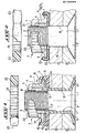
- FIG. 1 is a view in elevation and partial axial section of an assembly device according to the invention, in the clamped position on two panels, and
- Figure 2 is an elevational view in partial axial section of another embodiment of the assembly device according to the invention.
- an assembly device constitutes a bolt essentially comprising a screw 1 externally threaded at 2 to receive an elastic and self-locking nut 3, said bolt being intended to assemble various parts, such as plates or panels A and B, made of a composite material, that is to say a material essentially constituted by fibers of carbon, glass or the like, embedded in a given configuration in a synthetic resin such as for example an epoxy resin.
- the composite materials have excellent mechanical properties, but their assembly remains delicate due in particular to their brittleness in terms of matting, to their possible variation in volume as a function of humidity. , and the problems of galvanic corrosion they cause. Also, the structure of the bolt of the invention is very specific so as to take into account all these problems in order to achieve a perfect assembly.
- the nut 3 consists of a threaded barrel 4 connected via an annular part 5 to an outer skirt 6 coaxial with the barrel 4 and provided at its free end with a peripheral base 7.
- annular space 8 is formed between the underside 4a of the barrel 4 and the underside 7a of the base 7.
- the thread 2 of the screw 1 is, as seen in the figures, produced on only the end part of this screw to cooperate with the barrel threaded 4 of the nut.
- the said screw comprises a smooth ftlt marked at 10 and passing through an orifice formed in the two panels A and B.
- a sleeve 11 of electrically tight plastic material vis-à-vis the composite material of the panels A and B is provided around the smooth part 10 of the screw 1, and is extended by a part 12 to cover the entire underside 13 of the head 9 of the screw 1.
- the end of the sleeve 11 facing the annular space 8 is preferably chamfered, as seen in 14.
- annular element 15 of plastic which, like the sleeve 11, is also electrically tight vis-à-vis the composite material of the panels A and B.
- This element 15 encloses a washer 16, preferably metallized, this washer being interposed between the lower face 7a of the base 7 and the part 15a of the annular element 15 which forms the bearing face of the nut on the panels to be assembled, as can be seen indeed in FIG. 1.
- the washer 16 has an orifice 17 whose diameter corresponds to the diameter of the internal periphery 6a of the skirt 6 of the nut.
- the chamfered end 14 of the plastic sleeve around the screw extends beyond the thickness of the panels A and B to be assembled. But it could very well without departing from the scope of the invention, use a sleeve 11 of length slightly less than the thickness of the panels A and B, which would avoid delamination phenomena during the insertion of the screw 1 with its sleeve 11 into the orifice of the panels. In this regard, the chamfered or pointed end 14 of the sleeve 11 will facilitate the insertion and avoid any possible delamination during this insertion.
- the sleeve 11, 12 and the annular element 15 captive on the base 7 of the nut produce a perfect electrical seal with respect to the composite material of the panels to be assembled, and such as to avoid any galvanic corrosion of the screw 1 and the nut 3 which, as a result, can be made of a conventional and inexpensive material, such as for example aluminum.
- the electrical seal in question is quite simply produced by a layer of insulating varnish 19 coating the smooth part 10 of the screw 1 and the entire head 9 of this screw, and by a layer of insulating varnish 20 coating the annular element 15 mounted captively on the base 7 of the nut.
- a layer of insulating varnish 19 coating the smooth part 10 of the screw 1 and the entire head 9 of this screw
- a layer of insulating varnish 20 coating the annular element 15 mounted captively on the base 7 of the nut.
- the nature and thickness of the varnish layer 19, 20 will obviously be chosen so as to obtain the desired electrical tightness, it being understood that the varnish layer must have a certain solidity to resist friction during the operation d 'assembly.
- the outer periphery of the skirt 6 is provided with teeth, grooves or the like 22, as seen in FIGS. 1 and 2. These teeth can be in an appropriate number so as to correspond to the teeth or grooves of a wrench, for example of the dynanometric type, and allowing direct rotation of the nut.
- a ring 23 which is shown in the figures as being separate from the nut, but which, in reality, is integral with the skirt 6 of said nut.
- This ring is internally provided with teeth 24 meshing with the teeth 22 of the skirt 6, and the periphery 25 of this ring is for example hexagonal to allow it to be driven by a key.
- this ring 23 which is initially secured to the nut, may break for a tightening torque greater than a predetermined value.
- a tightening torque greater than a predetermined value.
Abstract
Description
La présente invention a essentiellement pour objet un dispositif du type boulon pour l'assemblage de matériaux composites revêtant par exemple la forme de plaques ou panneaux constitués par des fibres enrobées d'une résine synthétique ou analogue.The present invention essentially relates to a device of the bolt type for assembling composite materials, for example taking the form of plates or panels made up of fibers coated with a synthetic resin or the like.
Dans l'industrie aéronautique, on utilise actuellement de plus en plus des matériaux composites qui remplacent avantageusement les matériaux que l'on utilisait traditionnellement pour réaliser telle ou telle pièce ou partie d'un. aéronef. Cependant, l'assemblage de telles pièces en matériau composite n'est pas sans poser de nombreux problèmes.In the aeronautical industry, composite materials are currently being used more and more which advantageously replace the materials which were traditionally used to produce such or such part or part of one. aircraft. However, the assembly of such pieces of composite material is not without posing many problems.
En effet, bien que ces matériaux soient avantageux sur le plan notamment de la légèreté et de leurs propriétés mécaniques très élevées, ils présentent généralement une mauvaise résistance à la compression et au matage et sont souvent sensibles à l'humidité de sorte que leur volume peut varier. Tout cela, comme on le comprend, pose de nombreux problèmes eu égard à l'assemblage des pièces en matériaux composites. ,Indeed, although these materials are advantageous in particular in terms of lightness and their very high mechanical properties, they generally have poor resistance to compression and dulling and are often sensitive to humidity so that their volume can vary. All this, as we understand, poses many problems with regard to the assembly of parts made of composite materials. ,
C'est ainsi que les techniques usuelles de collage ne peuvent pas être utilisées, car les efforts sur les joints collés peuvent entraîner des délaminages ou des arrachements du matériau composite constituant les pièces collées. De même, les techniques de rivetage sont interdites, car les chocs et contraintes développées lors de la formation des têtes de rivet peuvent endommager gravement le composite. Aussi, on utilise actuellement des boulons pour réaliser ces assemblages, mais les résultats sont loin d'être satisfaisants.This is how the usual bonding techniques cannot be used, since the forces on the bonded joints can lead to delamination. or tearing of the composite material constituting the bonded parts. Likewise, riveting techniques are prohibited because the shocks and stresses developed during the formation of rivet heads can seriously damage the composite. Also, bolts are currently used to make these assemblies, but the results are far from satisfactory.
En effet, avec les boulons classiques, il y a un gros risque, lors du serrage de l'écrou, de dépasser la résistance maximum au matage des matériaux composites. De plus, les matériaux constituant les boulons classiques possèdent un potentiel galvanique sensiblement différent de celui des matériaux composites. Par conséquent, le joint boulonné procure un effet de pile qui entraîne une destruction très rapide du boulon sous l'effet d'une corrosion dite galvanique. On peut bien sùr remédier à cela en utilisant pour le boulon des matériaux très nobles tels que par exemple des alliages de titane, mais ces matériaux sont extrêmement coûteux et surabondants au niveau de leurs propriétés mécaniques compte tenu de la faible pression de matage admissible. Enfin, du fait de l'absence d'élasticité des boulons classiques, ceux- ci ne peuvent pas absorber les variations d'épaisseur des éléments composites, de sorte qu'une rupture de l'assemblage peut se produire, ce qui doit évidemment être évité à tout prix dans l'industrie aéronautique.Indeed, with conventional bolts, there is a big risk, when tightening the nut, of exceeding the maximum resistance to knocking of composite materials. In addition, the materials constituting conventional bolts have a galvanic potential significantly different from that of composite materials. Consequently, the bolted joint provides a pile effect which results in very rapid destruction of the bolt under the effect of so-called galvanic corrosion. This can of course be remedied by using very noble materials for the bolt such as for example titanium alloys, but these materials are extremely expensive and superabundant in terms of their mechanical properties given the low permissible mating pressure. Finally, due to the lack of elasticity of conventional bolts, these cannot absorb variations in the thickness of the composite elements, so that a rupture of the assembly can occur, which must obviously be avoided at all costs in the aeronautical industry.
La présente invention a pour but de remédier à tous les inconvénients ci-dessus en proposant un boulon spécial pour l'assemblage de matériaux composites, lequel boulon, en raison notamment de son élasticité et de ses propriétés d'isolation électrique, présente toutes les qualités requises et indispensables pour fixer les pièces en matériaux composites utilisées en aéronautique.The present invention aims to remedy all the above drawbacks by proposing a special bolt for the assembly of composite materials, which bolt, due in particular to its elasticity and its electrical insulation properties, has all the qualities required and essential for fix parts made of composite materials used in aeronautics.
A cet effet, l'invention a pour objet un dispositif d'assemblage de matériaux composites revêtant par exemple la forme de plaques ou panneaux constitués par des fibres enrobées d'une résine synthétique ou analogue, et du type comprenant une vis extérieurement filetée sur au moins une partie de sa longueur pour pouvoir coopérer avec un écrou auto-blocable formé d'un canon intérieur taraudé et raccordé à une jupe extérieure coaxiale audit canon et pourvue à son extrémité libre d'une embase périphérique, caractérisé en ce qu'autour de ladite embase est monté captif un élément annulaire électriquement étanche vis-à-vis du matériau composite sur lequel il prend appui, tandis qu'autour de la partie non filetée de la vis traversant lesdits panneaux est prévu un manchon qui est aussi électriquement étanche vis-à-vis du matériau composite et qui s'étend sur au moins le dessous de la tête devis.To this end, the subject of the invention is a device for assembling composite materials, for example taking the form of plates or panels made up of fibers coated with a synthetic resin or the like, and of the type comprising an externally threaded screw on at at least part of its length in order to be able to cooperate with a self-locking nut formed by an internal threaded barrel and connected to an outer skirt coaxial with said barrel and provided at its free end with a peripheral base, characterized in that around said base is mounted captive an annular element electrically tight vis-à-vis the composite material on which it is supported, while around the non-threaded part of the screw passing through said panels is provided a sleeve which is also electrically tight vis- with respect to the composite material and which extends over at least the underside of the quotation head.
On comprend donc déjà que les qualités d'élasticité de l'écrou et d'étanchéité électrique du boulon vis-à-vis du matériau composite, rendent celui-ci tout à fait apte à réaliser un assemblage qui soit parfaitement rigide et fiable dans le temps. En effet, l'élasticité de l'écrou permettra toujours de rattraper les variations possibles de l'épaisseur des panneaux composites. Quant à l'étanchéité électrique, elle permettra d'éviter toute corrosion galvanique du boulon qui, de ce fait, pourra avantageusement être réalisé en un matériau peu coûteux, tel qu'un alliage d'aluminium.It is therefore already understood that the qualities of elasticity of the nut and electrical tightness of the bolt vis-à-vis the composite material, make it quite suitable for producing an assembly which is perfectly rigid and reliable in the time. Indeed, the elasticity of the nut will always make it possible to make up for possible variations in the thickness of the composite panels. As for the electrical seal, it will prevent any galvanic corrosion of the bolt which, therefore, can advantageously be made of an inexpensive material, such as an aluminum alloy.
Suivant une autre caractéristique de l'invention, l'élément annulaire captif autour de l'embase de l'écrou, ainsi que le manchon autour de la vis sont tous deux réalisés en une matière plastique isolante.According to another characteristic of the invention, the annular captive element around the base of the nut, as well as the sleeve around the screw are both made of an insulating plastic material.
Suivant un autre mode de réalisation, l'élément annulaire captif est entièrement revêtu d'un vernis électriquement isolant, tandis que le manchon précité est lui aussi constitué par un revêtement de vernis isolant sur la partie non filetée de la vis et sur la tête de vis.According to another embodiment, the captive annular element is entirely coated with an electrically insulating varnish, while the aforementioned sleeve is also constituted by a coating of insulating varnish on the unthreaded part of the screw and on the head of screw.
Dans le cas où l'élément annulaire captif est en matière plastique, cet élément enserre une rondelle ou analogue interposée entre l'embase de la jupe et une partie de l'élément annulaire formant face d'appui de l'écrou sur le matériau composite.In the case where the captive annular element is made of plastic, this element encloses a washer or the like interposed between the base of the skirt and a part of the annular element forming the bearing face of the nut on the composite material .
Ainsi, une telle rondelle, de préférence métallique, empêchera l'élément annulaire captif de tourner avec l'écrou lors du serrage.Thus, such a washer, preferably metallic, will prevent the captive annular element from turning with the nut during tightening.
On ajoutera ici que cette rondelle possède un orifice dont le diamètre correspond au diamètre intérieur de la jupe de l'écrou.It will be added here that this washer has an orifice whose diameter corresponds to the inside diameter of the skirt of the nut.
Suivant encore une autre caractéristique de l'invention, le filetage de la vis et/ou le taraudage du canon de l'écrou sont munis d'au moins un dépôt de matière plastique assurant l'auto-freinage de l'écrou.According to yet another characteristic of the invention, the thread of the screw and / or the tapping of the nut barrel are provided with at least one plastic deposit ensuring the self-braking of the nut.
Le dispositif de l'invention est encore caractérisé par le fait qu'en vue d'effectuer le serrage de l'écrou, la périphérie externe de la jupe est munie de dents, cannelures ou analogues et éventuellement d'une bague solidaire de ladite jupe pour permettre l'entraînement en rotation de l'écrou, laquelle bague est susceptible de se rompre pour un couple de serrage supérieur à une valeur prédéterminée.The device of the invention is further characterized in that, in order to tighten the nut, the external periphery of the skirt is provided with teeth, grooves or the like and optionally with a ring integral with said skirt to allow driving the nut in rotation, which ring is liable to break for a tightening torque greater than a predetermined value.
Selon une autre caractéristique de l'invention, lorsque l'écrou est en position bloquée, le manchon isolant autour de la vis s'étend au-delà de l'épaisseur des panneaux assemblés, dans un espace annulaire ménagé entre la face inférieure du canon et la face inférieure de la jupe.According to another characteristic of the invention, when the nut is in the locked position, the insulating sleeve around the screw extends beyond the thickness of the assembled panels, in an annular space formed between the underside of the barrel and the underside of the skirt.
Dans le cas où le manchon précité est en matière . plastique électriquement isolante, on prévoit éventuellement un chanfrein à l'extrémité de ce manchon . en regard de l'espace annulaire précité, l'extrémité de ce manchon pouvant s'étendre au-delà ou en deçà de l'épaisseur des panneaux assemblés.In the case where the aforementioned sleeve is made of material. electrically insulating plastic, a chamfer is possibly provided at the end of this sleeve. opposite the abovementioned annular space, the end of this sleeve being able to extend beyond or below the thickness of the assembled panels.
L'invention vise encore un assemblage de matériaux composites revêtant par exemple la forme de plaques ou panneaux, lequel assemblage est réalisé à l'aide d'au moins un dispositif répondant aux caractéristiques sus-mentionnées..The invention also relates to an assembly of composite materials, for example in the form of plates or panels, which assembly is carried out using at least one device meeting the characteristics mentioned above.
Mais d'autres caractéristiques et avantages de l'invention apparaîtront mieux dans la description détaillée qui suit et se réfère aux dessins annexés, donnés uniquement à titre d'exemple, et dans lesquels:However, other characteristics and advantages of the invention will appear better in the detailed description which follows and refers to the appended drawings, given solely by way of example, and in which:
La figure 1 est une vue en élévation et coupe axiale partielle d'un dispositif d'assemblage selon l'invention, en position serrée sur deux panneaux, etFIG. 1 is a view in elevation and partial axial section of an assembly device according to the invention, in the clamped position on two panels, and
La figure 2 est une vue en élévation et en coupe axiale partielle d'un autre mode de réalisation de dispositif d'assemblage conforme à l'invention.Figure 2 is an elevational view in partial axial section of another embodiment of the assembly device according to the invention.
En se reportant à ces figures, on voit qu'un dispositif d'assemblage selon l'invention constitue un boulon comprenant essentiellement une vis 1 extérieurement filetée en 2 pour recevoir un écrou 3 élastique et auto-blocable, ledit boulon étant destiné à assembler des pièces diverses, telles que des plaques ou panneaux A et B, réalisées en un matériau composite, c'est-à-dire un matériau essentiellement constitué par des fibres de carbone, de verre ou analogue, noyées suivant une configuration donnée dans une résine synthétique telle que par exemple une résine époxy.Referring to these figures, it can be seen that an assembly device according to the invention constitutes a bolt essentially comprising a
Comme cela est expliqué au début de la présente description, les matériaux composites présentent d'excellentes propriétés mécaniques, mais leur assemblage demeure délicat en raison notamment de leur fragilité sur le plan du matage, de leur variation possible de volume en fonction de l'humidité, et des problèmes de corrosion galvanique qu'ils engendrent. Aussi, la structure du boulon de l'invention est très particulière de façon à prendre en compte tous ces problèmes en vue de réaliser un assemblage parfait.As explained at the beginning of the present description, the composite materials have excellent mechanical properties, but their assembly remains delicate due in particular to their brittleness in terms of matting, to their possible variation in volume as a function of humidity. , and the problems of galvanic corrosion they cause. Also, the structure of the bolt of the invention is very specific so as to take into account all these problems in order to achieve a perfect assembly.
A cet.effet, l'écrou 3 est constitué par un canon taraudé 4 raccordé par l'intermédiaire d'une partie annulaire 5 à une jupe extérieure 6 coaxiale au canon 4 et pourvue à son extrémité libre d'une embase périphérique 7.For this purpose, the
Comme on le voit bien sur les figures 1 et 2, un espace annulaire 8 est ménagé entre la face inférieure 4a du canon 4 et la face inférieure 7a de l'embase 7. Le filetage 2 de la vis 1 est, comme on le voit sur les figures, réalisé sur seulement la partie d'extrémité de cette vis pour coopérer avec le canon taraudé 4 de l'écrou. Entre le filetage 2 et la tête 9 de la vis 1, on voit que ladite vis comporte un ftlt lisse repéré en 10 et traversant un orifice ménagé dans les deux panneaux A et B.As can be seen in Figures 1 and 2, an
Dans le mode de réalisation illustré par la figure 1, un manchon 11 en matière plastique électriquement étanche vis-à-vis du matériau composite des panneaux A et B est prévu autour de la partie lisse 10 de la vis 1, et se prolonge par une partie 12 pour recouvrir la totalité du dessous 13 de la tête 9 de la vis 1. L'extrémité du manchon 11 en regard de l'espace annulaire 8 est de préférence chanfreinée, comme on le voit en 14.In the embodiment illustrated in FIG. 1, a
Sur l'embase 7 de l'écrou est monté captif un élément annulaire 15 en matière plastique qui, comme le manchon 11, est aussi électriquement étanche vis-à-vis du matériau composite des panneaux A et B. Cet élément 15 enserre une rondelle 16, de préférence métalliqué, cette rondelle étant interposée entre la face inférieure 7a de l'embase 7 et la partie 15a de l'élément annulaire 15 qui forme face d'appui de l'écrou sur les panneaux à assembler, comme on le voit bien sur la figure 1. On voit également sur cette figure que la rondelle 16 possède un orifice 17 dont le diamètre correspond au diamètre de la périphérie interne 6a de la jupe 6 de l'écrou.On the
Comme cela est bien visible sur la figure 1, l'extrémité chanfreinée 14 du manchon en plastique autour de la vis s'étend au-delà de l'épaisseur des panneaux A et B à assembler. Mais on pourrait très bien sans sortir du cadre de l'invention, utiliser un manchon 11 de longueur légèrement inférieure à l'épaisseur des panneaux A et B, ce qui permettrait d'éviter les phénomènes de délaminage lors de l'insertion de la vis 1 avec son manchon 11 dans l'orifice des panneaux. A cet égard, l'extrémité chanfreinée ou en ogive 14 du manchon 11 facilitera l'insertion et évitera tout délaminage possible, lors de cette insertion. En effet, on sait qu'en aéronautique notamment, il faut monter les vis avec un certain serrage dans l'alésage destiné à les recevoir, ceci afin d'éviter les efforts de cisaillage et d'augmenter les durées de vie à la fatigue des éléments assemblés. Ceci veut dire, dans le cas présent, que le diamètre extérieur du manchon 11 doit être légèrement supérieur au diamètre de l'alésage dans les panneaux A et B. Dans ces conditions, le chanfreinage 14 et éventuellement une longueur de manchon inférieure à celle de l'épaisseur des panneaux éviteront ou, à tout le moins minimiseront le délaminage, ce qui est indispensable dans le cas de matériaux composites si l'on veut préserver leurs propriétés mécaniques.As is clearly visible in Figure 1, the chamfered end 14 of the plastic sleeve around the screw extends beyond the thickness of the panels A and B to be assembled. But it could very well without departing from the scope of the invention, use a
Pour réaliser l'assemblage des panneaux A et B, il suffit, comme on le comprend, de visser l'écrou sur la vis 1, la partie 15a de l'élément captif 15 prenant appui sur la surface 18 du panneau A. Il faut remarquer ici, que lors de la rotation de .l'écrou, l'élément en plastique 15 captif autour de l'embase 7 sera immobilisé en rotation grâce à la rondelle métallique 16, puisque les coefficients de frottement entre rondelle et embase d'une part, et entre rondelle et partie 15a d'autre part, sont différents. Enfin, on insistera encore sur le fait que le manchon 11, 12 et l'élément annulaire 15 captif sur l'embase 7 de l'écrou réalisent une étanchéité électrique parfaite vis-à-vis du matériau composite des panneaux à assembler, et de nature à éviter toute corrosion galvanique de la vis 1 et de l'écrou 3 qui, de ce fait, peuvent être réalisés en un matériau classique et peu coûteux, tel que par exemple l'aluminium.To assemble the panels A and B, it suffices, as is understood, to screw the nut onto the
Dans le mode de réalisation illustré sur la figure 2, l'étanchéité électrique en question est tout simplement réalisée par une couche de vernis isolant 19 revêtant la partie lisse 10 de la vis 1 et l'intégralité de la tête 9 de cette vis, et par une couche de vernis isolant 20 revêtant l'élément annulaire 15 monté captif sur l'embase 7 de l'écrou. On voit ici que la rondelle entre embase 7 et élément 15 a été supprimée, mais on pourrait très bien prévoir l'interposition d'une telle rondelle comme dans le cas de la figure 1, sans sortir du cadre de l'invention. La nature et l'épaisseur de la couche de vernis 19, 20 seront évidemment choisies de façon à obtenir l'étanchéité électrique recherchée, étant bien entendu que la couche de vernis doit posséder une certaine solidité pour résister aux frottements lors de l'opération d'assemblage.In the embodiment illustrated in FIG. 2, the electrical seal in question is quite simply produced by a layer of insulating
On a montré schématiquement en 21 sur les figures 1 et 2 un dépôt de matière plastique assurant l'auto- freinage de l'écrou comme cela est connu en soi.There has been shown schematically at 21 in FIGS. 1 and 2 a deposit of plastic material ensuring self-braking of the nut as is known per se.
Pour permettre le serrage de l'écrou, la périphérie externe de la jupe 6 est munie de dents, cannelures ou analogues 22, comme on le voit sur les figures 1 et 2. Ces dents peuvent être en un nombre approprié de façon à correspondre aux dents ou cannelures d'une clé, par exemple du type dynanométrique, et permettant directement l'entraînement en rotation de l'écrou. Pour entraîner l'écrou, on peut également prévoir une bague 23 qui est représentée sur les figures comme étant séparée de l'écrou, mais qui, en réalité, est solidaire de la jupe 6 dudit écrou. Cette bague est intérieurement munie de dents 24 engrenant avec les dents 22 de la jupe 6, et la périphérie 25 de cette bague est par exemple hexagonale pour permettre son entrainement par une clé. Avantageusement, cette bague 23, qui est initialement solidaire de l'écrou, pourra se rompre pour un couple de serrage supérieur à une valeur prédéterminée. On comprend tout l'intérêt de l'utilisation d'une telle bague dans le cas de l'assemblage de matériaux composites sur lesquels il convient bien évidemment d'appliquer une force de serrage très précise compte tenu notamment de leur faible résistance au matage. En d'autres termes, on évitera de cette façon tout endommagement de l'assemblage.To allow tightening of the nut, the outer periphery of the
On a donc réalisé suivant l'invention un boulon spécial qui satisfait toutes les conditions requises pour réaliser l'assemblage de matériaux composites et à savoir;
- - une élasticité suffisante pour absorber les variations de volume du matériau composite en fonction de l'humidité;
- - une étanchéité électrique parfaite vis-à-vis du matériau composite, ce qui supprime toute corrosion galvanique et permet par conséquent de réduire le coût du matériau de la vis et de l'écrou qui peuvent être tout simplement en aluminium;
- - un serrage efficace des matériaux composites assemblés, et ce sans risque de matage; et
- - la diminution au maximum du risque de délaminage, notamment lorsque la vis traverse l'alésage des matériaux composites à assembler. C'est dire que les fibres du matériau composite ne subiront aucune contrainte tant au montage de la vis qu'au serrage du boulon.
- - sufficient elasticity to absorb the variations in volume of the composite material as a function of humidity;
- - perfect electrical tightness with respect to the composite material, which eliminates any galvanic corrosion and consequently makes it possible to reduce the cost of the material of the screw and the nut which may simply be made of aluminum;
- - effective clamping of assembled composite materials, without the risk of dulling; and
- - minimizing the risk of delamination, especially when the screw crosses the bore of the composite materials to be assembled. This means that the fibers of the composite material will not be subjected to any stress as much when mounting the screw as when tightening the bolt.
Bien entendu, l'invention n'est nullement limitée aux modes de réalisation décrits et illustrés qui n'ont été donnés qu'à titre d'exemple. Au contraire, l'invention comprend tous les équivalents techniques des moyens décrits ainsi que leurs combinaisons, si celles-ci sont effectuées suivant son esprit.Of course, the invention is in no way limited to the embodiments described and illustrated which have not have been given only as an example. On the contrary, the invention includes all the technical equivalents of the means described as well as their combinations, if these are carried out according to the spirit.
Claims (10)
Applications Claiming Priority (2)
| Application Number | Priority Date | Filing Date | Title |
|---|---|---|---|
| FR8308838A FR2546580B1 (en) | 1983-05-27 | 1983-05-27 | COMPOSITE MATERIAL ASSEMBLY DEVICE |
| FR8308838 | 1983-05-27 |
Publications (2)
| Publication Number | Publication Date |
|---|---|
| EP0128080A1 true EP0128080A1 (en) | 1984-12-12 |
| EP0128080B1 EP0128080B1 (en) | 1986-11-20 |
Family
ID=9289264
Family Applications (1)
| Application Number | Title | Priority Date | Filing Date |
|---|---|---|---|
| EP19840401058 Expired EP0128080B1 (en) | 1983-05-27 | 1984-05-23 | Device for assembling composite materials |
Country Status (4)
| Country | Link |
|---|---|
| EP (1) | EP0128080B1 (en) |
| DE (1) | DE3461386D1 (en) |
| ES (1) | ES289476Y (en) |
| FR (1) | FR2546580B1 (en) |
Cited By (5)
| Publication number | Priority date | Publication date | Assignee | Title |
|---|---|---|---|---|
| EP0254481A1 (en) * | 1986-07-24 | 1988-01-27 | Microdot Inc. | Composite core fastener |
| EP0269458A1 (en) * | 1986-11-28 | 1988-06-01 | British Aerospace Public Limited Company | Anti-lightning strike fasteners for composite material aircraft structures |
| GB2225825A (en) * | 1988-12-09 | 1990-06-13 | Fort Vale Eng Ltd | Swing bolt assembly for a pressure vessel |
| CN105065416A (en) * | 2015-07-23 | 2015-11-18 | 海盐欧亚特汽配有限公司 | Wheel nut assembly |
| FR3036362A1 (en) * | 2015-05-21 | 2016-11-25 | Peugeot Citroen Automobiles Sa | IMPROVED FIXING SYSTEM |
Citations (6)
| Publication number | Priority date | Publication date | Assignee | Title |
|---|---|---|---|---|
| FR1126784A (en) * | 1955-06-28 | 1956-11-30 | Deutsche Edelstahlwerke Ag | Method to prevent seizing of metal parts |
| GB929807A (en) * | 1960-01-26 | 1963-06-26 | United Carr Fastener Corp | Improvements in or relating to sealing nut assemblies |
| FR2142201A5 (en) * | 1971-06-16 | 1973-01-26 | Simmonds Sa | |
| US3742583A (en) * | 1972-01-14 | 1973-07-03 | Standard Pressed Steel Co | Method of using twist-off nut to assemble a joint |
| US4102036A (en) * | 1976-09-17 | 1978-07-25 | Paul R. Briles | Method of installing a sleeve bolt in an opening |
| FR2407383A1 (en) * | 1977-10-28 | 1979-05-25 | Messerschmitt Boelkow Blohm | CONNECTION ELEMENT, PREFERRED FOR SHEET PARTS IN LIGHT METAL ALLOYS, IN PARTICULAR FOR AERONAUTICAL CONSTRUCTION |
-
1983
- 1983-05-27 FR FR8308838A patent/FR2546580B1/en not_active Expired
-
1984
- 1984-05-23 DE DE8484401058T patent/DE3461386D1/en not_active Expired
- 1984-05-23 EP EP19840401058 patent/EP0128080B1/en not_active Expired
- 1984-05-25 ES ES1984289476U patent/ES289476Y/en not_active Expired
Patent Citations (6)
| Publication number | Priority date | Publication date | Assignee | Title |
|---|---|---|---|---|
| FR1126784A (en) * | 1955-06-28 | 1956-11-30 | Deutsche Edelstahlwerke Ag | Method to prevent seizing of metal parts |
| GB929807A (en) * | 1960-01-26 | 1963-06-26 | United Carr Fastener Corp | Improvements in or relating to sealing nut assemblies |
| FR2142201A5 (en) * | 1971-06-16 | 1973-01-26 | Simmonds Sa | |
| US3742583A (en) * | 1972-01-14 | 1973-07-03 | Standard Pressed Steel Co | Method of using twist-off nut to assemble a joint |
| US4102036A (en) * | 1976-09-17 | 1978-07-25 | Paul R. Briles | Method of installing a sleeve bolt in an opening |
| FR2407383A1 (en) * | 1977-10-28 | 1979-05-25 | Messerschmitt Boelkow Blohm | CONNECTION ELEMENT, PREFERRED FOR SHEET PARTS IN LIGHT METAL ALLOYS, IN PARTICULAR FOR AERONAUTICAL CONSTRUCTION |
Cited By (7)
| Publication number | Priority date | Publication date | Assignee | Title |
|---|---|---|---|---|
| EP0254481A1 (en) * | 1986-07-24 | 1988-01-27 | Microdot Inc. | Composite core fastener |
| EP0269458A1 (en) * | 1986-11-28 | 1988-06-01 | British Aerospace Public Limited Company | Anti-lightning strike fasteners for composite material aircraft structures |
| US4891732A (en) * | 1986-11-28 | 1990-01-02 | British Aerospace Plc | Anti-lightning strike fasteners for composite material aircraft structures |
| GB2225825A (en) * | 1988-12-09 | 1990-06-13 | Fort Vale Eng Ltd | Swing bolt assembly for a pressure vessel |
| GB2225825B (en) * | 1988-12-09 | 1993-08-18 | Fort Vale Eng Ltd | Swing bolt assembly for a pressure vessel |
| FR3036362A1 (en) * | 2015-05-21 | 2016-11-25 | Peugeot Citroen Automobiles Sa | IMPROVED FIXING SYSTEM |
| CN105065416A (en) * | 2015-07-23 | 2015-11-18 | 海盐欧亚特汽配有限公司 | Wheel nut assembly |
Also Published As
| Publication number | Publication date |
|---|---|
| EP0128080B1 (en) | 1986-11-20 |
| DE3461386D1 (en) | 1987-01-08 |
| FR2546580B1 (en) | 1986-10-24 |
| ES289476U (en) | 1986-10-01 |
| FR2546580A1 (en) | 1984-11-30 |
| ES289476Y (en) | 1987-06-01 |
Similar Documents
| Publication | Publication Date | Title |
|---|---|---|
| EP1234984B1 (en) | Assembling device for a composite panel and structure | |
| CA2870858C (en) | Fastening element for parts of an assembly | |
| EP2917969B1 (en) | Device for fixing an electrical connection terminal to a support | |
| FR2769067A1 (en) | SCREW ASSEMBLY WITH SUPPORT RING | |
| FR2915458A1 (en) | Aircraft fuselage, has junction including external ferrule fixed to panels and to internal ferrule by fixations that ensure fixation of internal ferrule with panels, where panels and external ferrule are made of composite material | |
| FR2551147A1 (en) | METHOD AND DEVICE FOR REDUCING MOUNTING FORCES AND COSTS IN A CONICAL BOLT SYSTEM | |
| WO2007118941A1 (en) | Device for displaying the correct tightening force for a nut mounted on a threaded rod | |
| FR2820402A1 (en) | DEVICE FOR HANGING AN ENGINE ON AN AIRCRAFT | |
| CA2788927C (en) | Method for repairing a flange of a housing | |
| FR2922612A1 (en) | STRUCTURAL DEVICE FOR IMPROVING THE STRENGTH OF STRUCTURE AT TEMPERATURE DILATIONS | |
| FR3063121A1 (en) | CRYSTAL INSERT, ELEMENT AND FIXING ASSEMBLY COMPRISING SUCH AN INSERT AND METHODS OF MANUFACTURING SUCH PIECES. | |
| EP0128080B1 (en) | Device for assembling composite materials | |
| FR2955366A1 (en) | Visualizing device for loosening of e.g. bolt in automobiles, has set of units gripped with another set of units when washers are applied to ring without prohibiting radial displacement of one of washers with respect to other washer | |
| EP3085626B1 (en) | Ball-jointed nut cap | |
| FR2585786A1 (en) | ATTACHED FASTENER AND ATTACHMENT ASSEMBLY | |
| FR2687195A1 (en) | Fastener with countersunk head, such as a rivet, for joining together pieces of composite material equipped with electrically conductive coatings and structure obtained by this joining | |
| FR2994888A1 (en) | ASSEMBLY OF TWO PIECES IN COMPOSITE MATERIAL | |
| EP3782264B1 (en) | Stator assembly | |
| FR3096840A1 (en) | Device and method for mechanical and electrical connection of two electrical power members | |
| FR2597935A1 (en) | THREADED ASSEMBLY ELEMENT, SUCH AS A SCREW, HAVING HEAD INSULATING RECOVERY | |
| EP3859170B1 (en) | Bolt comprising a nut and at least one washer obtained by hardening of a pasty material, method for installing said bolt and assembly comprising at least one such bolt | |
| EP0246954A2 (en) | Rotary hydraulic distributor and assembly process for such a distributor | |
| FR3117556A1 (en) | Assembly for a turbomachine | |
| FR2747741A1 (en) | Automobile starter motor, with pinion thrower, | |
| FR2727176A1 (en) | Conical connecting end shaft for fitting blower impeller |
Legal Events
| Date | Code | Title | Description |
|---|---|---|---|
| PUAI | Public reference made under article 153(3) epc to a published international application that has entered the european phase |
Free format text: ORIGINAL CODE: 0009012 |
|
| AK | Designated contracting states |
Designated state(s): BE DE GB IT NL SE |
|
| 17P | Request for examination filed |
Effective date: 19850204 |
|
| GRAA | (expected) grant |
Free format text: ORIGINAL CODE: 0009210 |
|
| AK | Designated contracting states |
Kind code of ref document: B1 Designated state(s): BE DE GB IT NL SE |
|
| REF | Corresponds to: |
Ref document number: 3461386 Country of ref document: DE Date of ref document: 19870108 |
|
| ITF | It: translation for a ep patent filed |
Owner name: DE DOMINICIS & MAYER S.R.L. |
|
| PLBE | No opposition filed within time limit |
Free format text: ORIGINAL CODE: 0009261 |
|
| STAA | Information on the status of an ep patent application or granted ep patent |
Free format text: STATUS: NO OPPOSITION FILED WITHIN TIME LIMIT |
|
| 26N | No opposition filed | ||
| PGFP | Annual fee paid to national office [announced via postgrant information from national office to epo] |
Ref country code: BE Payment date: 19910425 Year of fee payment: 8 |
|
| PGFP | Annual fee paid to national office [announced via postgrant information from national office to epo] |
Ref country code: GB Payment date: 19910513 Year of fee payment: 8 |
|
| PGFP | Annual fee paid to national office [announced via postgrant information from national office to epo] |
Ref country code: SE Payment date: 19910521 Year of fee payment: 8 |
|
| ITTA | It: last paid annual fee | ||
| PGFP | Annual fee paid to national office [announced via postgrant information from national office to epo] |
Ref country code: NL Payment date: 19910531 Year of fee payment: 8 |
|
| PGFP | Annual fee paid to national office [announced via postgrant information from national office to epo] |
Ref country code: DE Payment date: 19910628 Year of fee payment: 8 |
|
| PG25 | Lapsed in a contracting state [announced via postgrant information from national office to epo] |
Ref country code: GB Effective date: 19920523 |
|
| PG25 | Lapsed in a contracting state [announced via postgrant information from national office to epo] |
Ref country code: SE Effective date: 19920524 |
|
| PG25 | Lapsed in a contracting state [announced via postgrant information from national office to epo] |
Ref country code: BE Effective date: 19920531 |
|
| BERE | Be: lapsed |
Owner name: SOC. NATIONALE INDUSTRIELLE AEROSPATIALE Effective date: 19920531 Owner name: S.A. SIMMONDS Effective date: 19920531 |
|
| PG25 | Lapsed in a contracting state [announced via postgrant information from national office to epo] |
Ref country code: NL Effective date: 19921201 |
|
| NLV4 | Nl: lapsed or anulled due to non-payment of the annual fee | ||
| GBPC | Gb: european patent ceased through non-payment of renewal fee |
Effective date: 19920523 |
|
| PG25 | Lapsed in a contracting state [announced via postgrant information from national office to epo] |
Ref country code: DE Effective date: 19930202 |
|
| EUG | Se: european patent has lapsed |
Ref document number: 84401058.7 Effective date: 19921204 |