EP0127905A2 - Atmungsgerät mit automatischer Beatmungskorrektion - Google Patents
Atmungsgerät mit automatischer Beatmungskorrektion Download PDFInfo
- Publication number
- EP0127905A2 EP0127905A2 EP84200213A EP84200213A EP0127905A2 EP 0127905 A2 EP0127905 A2 EP 0127905A2 EP 84200213 A EP84200213 A EP 84200213A EP 84200213 A EP84200213 A EP 84200213A EP 0127905 A2 EP0127905 A2 EP 0127905A2
- Authority
- EP
- European Patent Office
- Prior art keywords
- circuit
- inspiration
- valve
- pressure
- accumulator
- Prior art date
- Legal status (The legal status is an assumption and is not a legal conclusion. Google has not performed a legal analysis and makes no representation as to the accuracy of the status listed.)
- Withdrawn
Links
Images
Classifications
-
- A—HUMAN NECESSITIES
- A61—MEDICAL OR VETERINARY SCIENCE; HYGIENE
- A61M—DEVICES FOR INTRODUCING MEDIA INTO, OR ONTO, THE BODY; DEVICES FOR TRANSDUCING BODY MEDIA OR FOR TAKING MEDIA FROM THE BODY; DEVICES FOR PRODUCING OR ENDING SLEEP OR STUPOR
- A61M16/00—Devices for influencing the respiratory system of patients by gas treatment, e.g. mouth-to-mouth respiration; Tracheal tubes
- A61M16/20—Valves specially adapted to medical respiratory devices
- A61M16/201—Controlled valves
- A61M16/206—Capsule valves, e.g. mushroom, membrane valves
-
- A—HUMAN NECESSITIES
- A61—MEDICAL OR VETERINARY SCIENCE; HYGIENE
- A61M—DEVICES FOR INTRODUCING MEDIA INTO, OR ONTO, THE BODY; DEVICES FOR TRANSDUCING BODY MEDIA OR FOR TAKING MEDIA FROM THE BODY; DEVICES FOR PRODUCING OR ENDING SLEEP OR STUPOR
- A61M16/00—Devices for influencing the respiratory system of patients by gas treatment, e.g. mouth-to-mouth respiration; Tracheal tubes
- A61M16/021—Devices for influencing the respiratory system of patients by gas treatment, e.g. mouth-to-mouth respiration; Tracheal tubes operated by electrical means
- A61M16/022—Control means therefor
- A61M16/024—Control means therefor including calculation means, e.g. using a processor
-
- A—HUMAN NECESSITIES
- A61—MEDICAL OR VETERINARY SCIENCE; HYGIENE
- A61M—DEVICES FOR INTRODUCING MEDIA INTO, OR ONTO, THE BODY; DEVICES FOR TRANSDUCING BODY MEDIA OR FOR TAKING MEDIA FROM THE BODY; DEVICES FOR PRODUCING OR ENDING SLEEP OR STUPOR
- A61M16/00—Devices for influencing the respiratory system of patients by gas treatment, e.g. mouth-to-mouth respiration; Tracheal tubes
- A61M16/10—Preparation of respiratory gases or vapours
- A61M16/1005—Preparation of respiratory gases or vapours with O2 features or with parameter measurement
- A61M16/1015—Preparation of respiratory gases or vapours with O2 features or with parameter measurement using a gas flush valve, e.g. oxygen flush valve
-
- A—HUMAN NECESSITIES
- A61—MEDICAL OR VETERINARY SCIENCE; HYGIENE
- A61M—DEVICES FOR INTRODUCING MEDIA INTO, OR ONTO, THE BODY; DEVICES FOR TRANSDUCING BODY MEDIA OR FOR TAKING MEDIA FROM THE BODY; DEVICES FOR PRODUCING OR ENDING SLEEP OR STUPOR
- A61M16/00—Devices for influencing the respiratory system of patients by gas treatment, e.g. mouth-to-mouth respiration; Tracheal tubes
- A61M16/20—Valves specially adapted to medical respiratory devices
- A61M16/201—Controlled valves
- A61M16/202—Controlled valves electrically actuated
- A61M16/203—Proportional
- A61M16/204—Proportional used for inhalation control
-
- A—HUMAN NECESSITIES
- A61—MEDICAL OR VETERINARY SCIENCE; HYGIENE
- A61M—DEVICES FOR INTRODUCING MEDIA INTO, OR ONTO, THE BODY; DEVICES FOR TRANSDUCING BODY MEDIA OR FOR TAKING MEDIA FROM THE BODY; DEVICES FOR PRODUCING OR ENDING SLEEP OR STUPOR
- A61M16/00—Devices for influencing the respiratory system of patients by gas treatment, e.g. mouth-to-mouth respiration; Tracheal tubes
- A61M16/20—Valves specially adapted to medical respiratory devices
- A61M16/201—Controlled valves
- A61M16/202—Controlled valves electrically actuated
- A61M16/203—Proportional
- A61M16/205—Proportional used for exhalation control
-
- A—HUMAN NECESSITIES
- A61—MEDICAL OR VETERINARY SCIENCE; HYGIENE
- A61M—DEVICES FOR INTRODUCING MEDIA INTO, OR ONTO, THE BODY; DEVICES FOR TRANSDUCING BODY MEDIA OR FOR TAKING MEDIA FROM THE BODY; DEVICES FOR PRODUCING OR ENDING SLEEP OR STUPOR
- A61M16/00—Devices for influencing the respiratory system of patients by gas treatment, e.g. mouth-to-mouth respiration; Tracheal tubes
- A61M16/10—Preparation of respiratory gases or vapours
- A61M16/105—Filters
- A61M16/1055—Filters bacterial
-
- A—HUMAN NECESSITIES
- A61—MEDICAL OR VETERINARY SCIENCE; HYGIENE
- A61M—DEVICES FOR INTRODUCING MEDIA INTO, OR ONTO, THE BODY; DEVICES FOR TRANSDUCING BODY MEDIA OR FOR TAKING MEDIA FROM THE BODY; DEVICES FOR PRODUCING OR ENDING SLEEP OR STUPOR
- A61M16/00—Devices for influencing the respiratory system of patients by gas treatment, e.g. mouth-to-mouth respiration; Tracheal tubes
- A61M16/10—Preparation of respiratory gases or vapours
- A61M16/105—Filters
- A61M16/106—Filters in a path
- A61M16/107—Filters in a path in the inspiratory path
-
- A—HUMAN NECESSITIES
- A61—MEDICAL OR VETERINARY SCIENCE; HYGIENE
- A61M—DEVICES FOR INTRODUCING MEDIA INTO, OR ONTO, THE BODY; DEVICES FOR TRANSDUCING BODY MEDIA OR FOR TAKING MEDIA FROM THE BODY; DEVICES FOR PRODUCING OR ENDING SLEEP OR STUPOR
- A61M16/00—Devices for influencing the respiratory system of patients by gas treatment, e.g. mouth-to-mouth respiration; Tracheal tubes
- A61M16/20—Valves specially adapted to medical respiratory devices
- A61M16/208—Non-controlled one-way valves, e.g. exhalation, check, pop-off non-rebreathing valves
-
- A—HUMAN NECESSITIES
- A61—MEDICAL OR VETERINARY SCIENCE; HYGIENE
- A61M—DEVICES FOR INTRODUCING MEDIA INTO, OR ONTO, THE BODY; DEVICES FOR TRANSDUCING BODY MEDIA OR FOR TAKING MEDIA FROM THE BODY; DEVICES FOR PRODUCING OR ENDING SLEEP OR STUPOR
- A61M16/00—Devices for influencing the respiratory system of patients by gas treatment, e.g. mouth-to-mouth respiration; Tracheal tubes
- A61M16/0003—Accessories therefor, e.g. sensors, vibrators, negative pressure
- A61M2016/0015—Accessories therefor, e.g. sensors, vibrators, negative pressure inhalation detectors
- A61M2016/0018—Accessories therefor, e.g. sensors, vibrators, negative pressure inhalation detectors electrical
- A61M2016/0021—Accessories therefor, e.g. sensors, vibrators, negative pressure inhalation detectors electrical with a proportional output signal, e.g. from a thermistor
-
- A—HUMAN NECESSITIES
- A61—MEDICAL OR VETERINARY SCIENCE; HYGIENE
- A61M—DEVICES FOR INTRODUCING MEDIA INTO, OR ONTO, THE BODY; DEVICES FOR TRANSDUCING BODY MEDIA OR FOR TAKING MEDIA FROM THE BODY; DEVICES FOR PRODUCING OR ENDING SLEEP OR STUPOR
- A61M16/00—Devices for influencing the respiratory system of patients by gas treatment, e.g. mouth-to-mouth respiration; Tracheal tubes
- A61M16/0003—Accessories therefor, e.g. sensors, vibrators, negative pressure
- A61M2016/0027—Accessories therefor, e.g. sensors, vibrators, negative pressure pressure meter
Definitions
- respirators in which the breathing gas is stored during the expiration phase and then returned to the use circuit during the inspiration phase, are intended mainly for the treatment of respiratory insufficiency and can be used in hospitals, at home, or still in first aid.
- the cyclically operated control device makes it possible to deliver ventilation to the user, that is to say a given quantity of breathable gas per unit of time, the parameters of which, in particular the frequency of the respiratory cycles, the duration of the inspiratory and expiratory times and the ratio between these inspiratory and expiratory times are displayed and modifiable at will.
- Ventilation can therefore be easily controlled and adjusted by the operator responsible for driving the respirator, usually a doctor.
- the object of the present invention is to overcome these difficulties and for this purpose proposes a respirator of the aforementioned type but also comprising an auxiliary supply circuit to provide an additional supply of breathable gas to the use circuit, an exhaust circuit to subtract a portion of the breathable gas to said use circuit and a ventilation correction device sensitive to pressure variations in the inspiration branch of the use circuit and to the duration of the inspiratory and expiratory times, said correction device controlling said circuits of supply and exhaust to supply or evacuate breathable gas respectively, according to said variations and said duration.
- the respirator according to the invention therefore makes it possible to increase or decrease the ventilation, automatically, as a function of the pressure in the circuit of use, which is dependent on the patient, that is to say on his reactions or of his condition.
- the aforementioned auxiliary supply circuit comprises a conduit connecting the supply circuit to the accumulator and provided with a solenoid valve and a calibrated orifice.
- the additional supply of breathable gas to the use circuit is made via the accumulator with a flow rate, the value of which depends on the calibrated orifice and on the time of opening of the solenoid valve.
- the aforementioned exhaust circuit comprises a venting pipe communicating with the accumulator and provided with a solenoid valve.
- the pressure in the operating circuit may in no case exceed a safety value Ps, this thanks to a safety valve provided in said circuit.
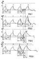
- the values I, E, T, as well as the quantity of gas injected, are adjusted by the operator so that they conform to the needs and characteristics of the patient.
- the value of P results from this setting.
- the corresponding respiratory cycles are represented in 1 and 2.
- the patient reacts with a inspiratory effort during the expiratory phase, that is to say between the moment when it has finished exhaling (A) and the start of the next inspiratory phase (B), imposed by the respirator.
- This inspiratory effort creates in the patient circuit, between A and B, a depression which reflects the insufficient ventilation (cycles 3 and 4).
- FIG. 2 in which the same letters denote the same parameters as in FIG. 1, relates to the case of a patient whose pulmonary passages are obstructed.
- cycle 3 the pressure rises sharply in the patient circuit. This results in an increase in the energy level in the accumulator and an increase in the pressure which continues with each cycle until reaching the value of the safety pressure Ps (cycle 4).
- the ventilation delivered by the respirator is too important.
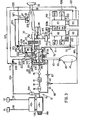
- the respirator according to the invention essentially comprises a circuit for supplying breathable gas 10, a distributor block 20, a utilization circuit or patient circuit. 30, a pneumatic accumulator 40, this circuit 30 and this accumulator receiving the breathable gas from the circuit 10 via the distributor 20, and an electric control device with cyclic action (50), the function of which is to control the successive cycles of inspiration and expiration and ensure the patient's breathing.
- the supply circuit 10 comprises two sources 11 and 12 of pressurized gas, for example, in the case where the patient must be ventilated with super-oxygenated air, a source of air and a source of oxygen.
- the sources 11 and 12 communicate, by conduits 110 and 120, with a pressure equalizer 13 which communicates itself, by conduits 130 and 131, with a mixer 14 provided with an adjustment knob 140 which allows the metering of the mixture of the two gases.
- the mixture 14 communicates with a pipe 15 provided with a pressure reducer 16 which reduces the gas pressure to a stable value, of the order of 1 bar, of a flow meter 17 and of a flow adjustment valve 18.
- the distributor 20 includes a venturi 21 whose injector 210, connected to the pipe 15, receives the breathable gas and the divergent 211 of which opens directly into an internal space 200 of the dispenser. Said space 200 cqmmunique with the circuit of use 30 by a valve of inspiration 22 housed in a compartment 201, with the accumulator 40 d i on the one hand via an accumulation valve 23 housed in a compartment 202 communicating with a passage 203 and on the other hand by a one-way valve 24 (letting the gas pass in the direction going from the accumulator 40 to the circuit 30) and finally with the atmosphere with an additional air valve 25.
- the compartment 201 communicates with the atmosphere by a calibrated valve 26 which prevents the pressure in the circuit 30 from exceeding the safety value Ps.
- the inspiration valve 22 comprises a seat 220, a pneumatic valve 221 connected, by a conduit 222, to a solenoid valve 223 which has the function of inflating and deflating said valve and communicates for this purpose, on the one hand, by a conduit 224, with the outlet of the divergent 211 from the venturi 21 and on the other hand, by a conduit 226, with the compartment 201 of the distributor 20.
- the accumulation valve 23 comprises a seat 230, a pneumatic valve 231 which communicates, via a conduit 232, with a solenoid valve 233 for inflating and deflating said valve.
- the solenoid valve 233 communicates on the one hand with the pipe 15, by means of a conduit 234 provided with a regulator 235, and on the other hand with the atmosphere by a purge 236.
- the use circuit 30 includes an inspiration branch 31 which communicates directly with the compartment 201 of the distributor 20 and an expiration branch 21, these two branches 31 and 32 communicating, via a common trunk 33 with a mask 34 for the patient.
- the branch 31 comprises a bacteriological filter 35 and a humidifier 36.
- the exhalation branch 32 communicates with the atmosphere by an exhalation valve 37.
- the exhalation valve 37 comprises a seat 370, a pneumatic valve 371 which communicates , by a conduit 372, with a solenoid valve 373 for inflating and deflating said valve.
- the solenoid valve 373 is connected on the one hand to the outlet of the divergent 211 via a conduit 374 and the aforementioned conduit 224 of the inspiration valve and on the other hand to the atmosphere by a purge 376.
- the accumulator 40 consists of an elastic balloon 41, called an integrating balloon, designed to store a part of breathable gas thus forming a buffer reserve and which is connected to the distributor 20 by a tube 42 provided with a safety valve 43.
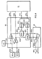
- the control device 50 essentially comprises an electronic clock 51 and a control member 52 constituted for example by a power amplifier and controlled by said clock via the conductors 512 and 513.
- the device 50 is provided for controlling, according to a determined program, the frequency of respiratory cycles 1 and the I / E ratio of inspiratory time to expiratory time for each respiratory cycle, this frequency and this ratio being adjustable by means of regulating members 510 and 511 respectively, constituted for example by potentiometers and associated with the clock 51.
- the control member 52 is connected, by a conductor 520, to the solenoid valve 223 and by a common conductor 521 to the solenoid valves 233 and 373 and it is intended to send to said solenoid valves, as a function of the piloting signals which it receives from the clock 51, signals which control their opening and closing and therefore the opening and closing of the pneumatic valves 22, 23 and 37.
- the operator can therefore impose on the patient a series of determined inspiratory and expiratory times.
- the respirator according to the invention comprises, in addition to the above-mentioned components, an auxiliary supply circuit 60, an exhaust circuit 70 and a ventilation correction device 80.
- the auxiliary supply circuit 60 essentially comprises a conduit 61 provided with a solenoid valve 62 which operates by all or nothing and a calibrated orifice 63.
- the conduit 61 directly connects the pipe 15 of the supply circuit 10 to the tubing 42 of accumulator 40.
- the exhaust circuit 70 comprises a pipe 71 for venting connected to the internal space 200 of the distributor 20 and provided, at its end, with a solenoid valve 72 which operates by all or nothing.
- the ventilation correction device 80 comprises a pressure sensor 81, an electronic computer 82 sensitive to the indications of said sensor and a control member 83, controlled by said computer.
- the sensor 81 for example of the piezoresistive type, is connected by a conduit 810 provided with a manometer 811, to the inspiration branch 31, it detects the pressure in said branch and delivers to the computer 82, by the intermediary of the electrical conductor 812, an electrical voltage proportional to said pressure.
- the computer 82 is provided to control the clock 51 so that it starts, when the pressure in the branch 31 reaches a determined minimum value Pm (depression) or a determined maximum value P M (less than or at most equal to the pressure Ps) security, an inhalation phase or an exhalation phase of anti - cipée, that is to say ahead of the inspiratory or expiratory phase that would normally be produced by the program determined by the control elements 510 and 511.
- the organs 510 and 511 in fact determine the frequency 1 of the respiratory cycles as well as the I / E ratio of inspiratory time to expiratory time, they consequently determine I and E.
- the fact of triggering in advance an inspiratory phase or an expiratory phase has as a consequence of shortening the expiration time or the inspiratory time of the programmed respiratory cycle, these two times then taking values Er and Ir, lower than E and I respectively.
- the computer 82 is also provided to store the times I and E and to determine the differences E - Er and 1 - Ir so as to control the duration of opening of the valves 62 and 72 as a function of these time differences E - Er and I - Ir.
- the computer 82 has two comparator circuits 820 a and 820 b for comparing the electrical voltages supplied by the sensor 81 with two reference voltages, one minimum, corresponding to the minimum pressure Pm, the other maximum, corresponding to the maximum pressure P M. These two reference voltages, and consequently the two pressures Pm and P M , can be chosen at will by the operator (with the condition P M ⁇ P S ) by means of the adjustment members 821 a and 821 b, constituted by example by potentiometers, and connected, by conductors 822 a and 822 b, to one of the inputs of each of the comparators.
- the comparators 820a and 820 b have their other input connected to the output of the sensor 81 by a conductor 812 and their output connected, by conductors 823 a and 823 b, to the time base (not shown) of the clock 51.
- the computer 82 also includes two memory circuits 824 a and 824 b and two subtracted circuits u rs 826 a and 826 b.
- the circuits 824 a and 824 b receive, at their input, the times I and E programmed by the clock 51 and put them in memory.
- These times I and E are calculated by a calculating member 825, connected by conductors 514 and 515, to the circuits (not shown) of the clock 51 which deliver the values 1 and I and are addressed to the memories 824 a and 824 b by conductors 825 a and 825 b.
- the subtractors 826 a and 826 b receive on the one hand the times I and E of the memories 824 a and 824 b via the conductors 827 a and 827 b and on the other hand the times Ir and Er of the comparators 820 a and 820 b via conductors 828 a and 828 b.
- the differences I - Ir and E - Er are addressed, by conductors 829 a and 829 b, to the control unit 83.
- the control member 83 comprises two amplifiers 830a and 830b tooth the inputs are connected to the subtractors 826a and 826b by the aforementioned conductors 829a and 829b, their outputs being connected to the solenoid valves 62 and 72 via the conductors 831 and 832 respectively, to control the opening and closing of said solenoid valves as a function of signals they receive from subtractors 826 a and 826 b.
- the clock 51 controls the control unit 52 so that it triggers an anticipated inspiratory phase.
- the expiration time is therefore shortened to a real value Er less than the time E programmed by the device 50.
- the subtractor 826a determines the difference between the expiration time E stored which should have taken place and the expiration time Er which has occurred .
- the energy level in the integrator balloon 41 increases, which leads to an increase in the inspiration flow.
- the ventilation then takes place according to cycles 3 and 4 of FIG. 5. Cycle 4 encroaches on cycle 3 and its peak pressure exceeds the value P of the preceding cycles.
- the ventilation becomes excessive as a result of an obstruction of the pulmonary passages of the patient, there follows an increase in pressure in the circuit of use.
- This pressure detected by the sensor 81 is converted into proportional electrical voltage which is received by the comparators 820a, 820b.
- the comparator 820 b sends an electrical signal to the clock 51 by the conductor 823 b and to the subtractor 826 b by the conductor 827 b.
- the clock 51 controls the control device 52 so that it triggers an early expiration phase.
- the inspiratory time is therefore shortened to a real value Ir lower than the inspiratory time I programmed by the device 50.
- the inspiration and expiration cycles then take the form represented by cycles 3 and 4 in FIG. 6.
- the peak pressure of cycle 3 reaches the value P M
- the peak pressure of cycle 4 is reduced to a value less than pm, due to the decompression of the balloon 41.
Landscapes
- Health & Medical Sciences (AREA)
- Emergency Medicine (AREA)
- Pulmonology (AREA)
- Engineering & Computer Science (AREA)
- Anesthesiology (AREA)
- Biomedical Technology (AREA)
- Heart & Thoracic Surgery (AREA)
- Hematology (AREA)
- Life Sciences & Earth Sciences (AREA)
- Animal Behavior & Ethology (AREA)
- General Health & Medical Sciences (AREA)
- Public Health (AREA)
- Veterinary Medicine (AREA)
- Respiratory Apparatuses And Protective Means (AREA)
Applications Claiming Priority (2)
| Application Number | Priority Date | Filing Date | Title |
|---|---|---|---|
| FR8012824 | 1980-06-10 | ||
| FR8012824A FR2483785A1 (fr) | 1980-06-10 | 1980-06-10 | Respirateur a correction automatique de ventilation |
Related Parent Applications (2)
| Application Number | Title | Priority Date | Filing Date |
|---|---|---|---|
| EP81400888A Division-Into EP0042321B1 (de) | 1980-06-10 | 1981-06-04 | Beatmungsgerät mit automatischer Belüftungskorrektion |
| EP81400888A Division EP0042321B1 (de) | 1980-06-10 | 1981-06-04 | Beatmungsgerät mit automatischer Belüftungskorrektion |
Publications (2)
| Publication Number | Publication Date |
|---|---|
| EP0127905A2 true EP0127905A2 (de) | 1984-12-12 |
| EP0127905A3 EP0127905A3 (de) | 1985-05-08 |
Family
ID=9242891
Family Applications (2)
| Application Number | Title | Priority Date | Filing Date |
|---|---|---|---|
| EP81400888A Expired EP0042321B1 (de) | 1980-06-10 | 1981-06-04 | Beatmungsgerät mit automatischer Belüftungskorrektion |
| EP84200213A Withdrawn EP0127905A3 (de) | 1980-06-10 | 1981-06-04 | Atmungsgerät mit automatischer Beatmungskorrektion |
Family Applications Before (1)
| Application Number | Title | Priority Date | Filing Date |
|---|---|---|---|
| EP81400888A Expired EP0042321B1 (de) | 1980-06-10 | 1981-06-04 | Beatmungsgerät mit automatischer Belüftungskorrektion |
Country Status (6)
| Country | Link |
|---|---|
| US (1) | US4401115A (de) |
| EP (2) | EP0042321B1 (de) |
| AT (1) | ATE17656T1 (de) |
| DE (1) | DE3173610D1 (de) |
| ES (1) | ES502870A0 (de) |
| FR (1) | FR2483785A1 (de) |
Cited By (4)
| Publication number | Priority date | Publication date | Assignee | Title |
|---|---|---|---|---|
| EP0273041A1 (de) * | 1986-03-31 | 1988-07-06 | Puritan-Bennett Corporation | Rechnergesteuertes positivatmungsdrucksystem |
| WO1991012042A1 (en) * | 1990-02-19 | 1991-08-22 | Basil Martin Wright | Medical ventilators |
| EP0796630A2 (de) * | 1996-03-21 | 1997-09-24 | Ohmeda Inc. | Sauerstoffspülvorrichtung für ein Narkosesystem |
| EP4079358A1 (de) * | 2021-04-23 | 2022-10-26 | Drägerwerk AG & Co. KGaA | Beatmungsgerät zur maschinellen beatmung eines patienten |
Families Citing this family (59)
| Publication number | Priority date | Publication date | Assignee | Title |
|---|---|---|---|---|
| DE3412118A1 (de) * | 1984-03-31 | 1985-10-10 | Allihn & Co Sauerstoffgeräte, 8000 München | Atemphasenregler |
| US4640277A (en) * | 1984-05-17 | 1987-02-03 | Texas College Of Osteopathic Medicine | Self-contained breathing apparatus |
| FR2565100B1 (fr) * | 1984-06-01 | 1988-08-26 | Air Liquide | Respirateur |
| US4595004A (en) * | 1984-09-17 | 1986-06-17 | Kurt Czech | Apparatus for the treatment of the lungs of humans or animals |
| US4651731A (en) * | 1984-09-17 | 1987-03-24 | Figgie International Inc. | Self-contained portable single patient ventilator/resuscitator |
| GB2164568B (en) * | 1984-09-21 | 1988-12-14 | Figgie Int Inc | Self-contained portable single patient ventilator/resuscitator |
| JPS61131756A (ja) * | 1984-11-30 | 1986-06-19 | 鳥取大学長 | 呼吸同調送気式濃縮酸素供給装置 |
| GB8511170D0 (en) * | 1985-05-02 | 1985-06-12 | Pneupac Ltd | Resuscitator/ventilator |
| US4686975A (en) * | 1985-05-03 | 1987-08-18 | Applied Membrane Technology, Inc. | Electronic respirable gas delivery device |
| US4747403A (en) * | 1986-01-27 | 1988-05-31 | Advanced Pulmonary Technologies, Inc. | Multi-frequency jet ventilation technique and apparatus |
| US4838259A (en) * | 1986-01-27 | 1989-06-13 | Advanced Pulmonary Technologies, Inc. | Multi-frequency jet ventilation technique and apparatus |
| US4784130A (en) * | 1986-12-04 | 1988-11-15 | The John Bunn Company | Flow controller |
| US5092326A (en) * | 1987-11-19 | 1992-03-03 | Winn Bryan D | Apparatus and method for a ventilator system |
| US4915103A (en) * | 1987-12-23 | 1990-04-10 | N. Visveshwara, M.D., Inc. | Ventilation synchronizer |
| US5038771A (en) * | 1990-01-25 | 1991-08-13 | Dietz Henry G | Method and apparatus for respiratory therapy using intermittent flow having automatic adjustment of a dose of therapeutic gas to the rate of breathing |
| DE4038871A1 (de) * | 1990-12-03 | 1992-06-04 | Peter Dr Sc Techn Schaller | Steuerung fuer ein beatmungsgeraet |
| GB9125467D0 (en) * | 1991-11-29 | 1992-01-29 | Mockridge Jeffrey N A | Neo-natal ventilation apparatus |
| FR2692152B1 (fr) | 1992-06-15 | 1997-06-27 | Pierre Medical Sa | Appareil d'aide a la respiration, notamment pour traiter l'apnee du sommeil. |
| WO1994006499A1 (fr) * | 1992-09-18 | 1994-03-31 | Pierre Medical S.A. | Dispositif d'aide a la respiration |
| FR2695830B1 (fr) * | 1992-09-18 | 1994-12-30 | Pierre Medical Sa | Dispositif d'aide à la respiration. |
| EP0667169B1 (de) * | 1994-01-12 | 1999-04-07 | Société d'Applications Industrielles Medicales et Electroniques ( SAIME) | Beatmungsgerät mit einem Atemunterstützungsverfahren unter erniedrigtem Druck |
| GB9413499D0 (en) * | 1994-07-05 | 1994-08-24 | Pneupac Ltd | Gas mixing devices for resuscitation/lung ventilation apparatus |
| US6866040B1 (en) | 1994-09-12 | 2005-03-15 | Nellcor Puritan Bennett France Developpement | Pressure-controlled breathing aid |
| FR2724322A1 (fr) * | 1994-09-12 | 1996-03-15 | Pierre Medical Sa | Dispositif d'aide respiratoire commande en pression |
| FR2724564B1 (fr) * | 1994-09-16 | 1997-04-04 | Boussignac Georges | Dispositif d'assistance respiratoire |
| WO1996024402A1 (en) * | 1995-02-08 | 1996-08-15 | Puritan-Bennett Corporation | Gas mixing apparatus for a ventilator |
| FR2732607B1 (fr) * | 1995-04-04 | 1997-08-29 | Saime Sarl | Appareil d'assistance respiratoire volumetrique muni d'un bloc-soupapes perfectionne |
| FR2755017B1 (fr) * | 1996-10-30 | 1998-12-18 | Taema | Dispositif d'assistance respiratoire |
| US5881723A (en) | 1997-03-14 | 1999-03-16 | Nellcor Puritan Bennett Incorporated | Ventilator breath display and graphic user interface |
| US6076523A (en) | 1998-01-15 | 2000-06-20 | Nellcor Puritan Bennett | Oxygen blending in a piston ventilator |
| SE9900368D0 (sv) * | 1999-02-04 | 1999-02-04 | Siemens Elema Ab | Narkosapparat |
| DE19931807C1 (de) * | 1999-07-08 | 2000-09-07 | Draeger Medizintech Gmbh | Beatmungsvorrichtung mit einem Überdruckventil |
| CA2379353C (en) * | 2002-03-28 | 2012-07-31 | Joseph Fisher | A new method for continuous measurement of flux of gases in the lungs during breathing |
| US7484508B2 (en) * | 2002-06-27 | 2009-02-03 | Yrt Limited | Method and device for monitoring and improving patient-ventilator interaction |
| US8021310B2 (en) | 2006-04-21 | 2011-09-20 | Nellcor Puritan Bennett Llc | Work of breathing display for a ventilation system |
| US7784461B2 (en) | 2006-09-26 | 2010-08-31 | Nellcor Puritan Bennett Llc | Three-dimensional waveform display for a breathing assistance system |
| CA2700878C (en) * | 2007-09-26 | 2018-07-24 | Breathe Technologies, Inc. | Methods and devices for providing inspiratory and expiratory flow relief during ventilation therapy |
| US20090165795A1 (en) * | 2007-12-31 | 2009-07-02 | Nellcor Puritan Bennett Llc | Method and apparatus for respiratory therapy |
| US8302602B2 (en) * | 2008-09-30 | 2012-11-06 | Nellcor Puritan Bennett Llc | Breathing assistance system with multiple pressure sensors |
| DE102009046541A1 (de) * | 2009-11-09 | 2011-05-12 | Medin Medical Innovations Gmbh | Druckluftsteuerungsvorrichtung für eine CPAP-Vorrichtung und entsprechendes CPAP-System |
| US9119925B2 (en) | 2009-12-04 | 2015-09-01 | Covidien Lp | Quick initiation of respiratory support via a ventilator user interface |
| US8335992B2 (en) | 2009-12-04 | 2012-12-18 | Nellcor Puritan Bennett Llc | Visual indication of settings changes on a ventilator graphical user interface |
| US8924878B2 (en) | 2009-12-04 | 2014-12-30 | Covidien Lp | Display and access to settings on a ventilator graphical user interface |
| US8499252B2 (en) | 2009-12-18 | 2013-07-30 | Covidien Lp | Display of respiratory data graphs on a ventilator graphical user interface |
| US9262588B2 (en) | 2009-12-18 | 2016-02-16 | Covidien Lp | Display of respiratory data graphs on a ventilator graphical user interface |
| CN102946933B (zh) * | 2010-06-22 | 2016-09-14 | 皇家飞利浦电子股份有限公司 | 呼吸接口装置 |
| US9364624B2 (en) | 2011-12-07 | 2016-06-14 | Covidien Lp | Methods and systems for adaptive base flow |
| US9498589B2 (en) | 2011-12-31 | 2016-11-22 | Covidien Lp | Methods and systems for adaptive base flow and leak compensation |
| US8844526B2 (en) | 2012-03-30 | 2014-09-30 | Covidien Lp | Methods and systems for triggering with unknown base flow |
| US10362967B2 (en) | 2012-07-09 | 2019-07-30 | Covidien Lp | Systems and methods for missed breath detection and indication |
| EP2916898A1 (de) * | 2012-11-09 | 2015-09-16 | Koninklijke Philips N.V. | System zur bereitstellung von druckimpulsen für die atemwege einer person |
| DE102012024672A1 (de) * | 2012-12-18 | 2014-06-18 | Dräger Medical GmbH | Beatmungsgerät und Verfahren zum Betrieb eines Beatmungsgerätes |
| CN103908726A (zh) * | 2012-12-29 | 2014-07-09 | 北京谊安医疗系统股份有限公司 | 基于电动电控呼吸机或麻醉机主动呼气阀的自动校验方法 |
| US9981096B2 (en) | 2013-03-13 | 2018-05-29 | Covidien Lp | Methods and systems for triggering with unknown inspiratory flow |
| US9808591B2 (en) | 2014-08-15 | 2017-11-07 | Covidien Lp | Methods and systems for breath delivery synchronization |
| US9950129B2 (en) | 2014-10-27 | 2018-04-24 | Covidien Lp | Ventilation triggering using change-point detection |
| US9925346B2 (en) | 2015-01-20 | 2018-03-27 | Covidien Lp | Systems and methods for ventilation with unknown exhalation flow |
| US11324954B2 (en) | 2019-06-28 | 2022-05-10 | Covidien Lp | Achieving smooth breathing by modified bilateral phrenic nerve pacing |
| US11672934B2 (en) | 2020-05-12 | 2023-06-13 | Covidien Lp | Remote ventilator adjustment |
Citations (2)
| Publication number | Priority date | Publication date | Assignee | Title |
|---|---|---|---|---|
| FR2159735A5 (de) * | 1971-11-10 | 1973-06-22 | Synthelabo | |
| FR2344278A1 (fr) * | 1976-03-19 | 1977-10-14 | Air Liquide | Respirateur |
Family Cites Families (10)
| Publication number | Priority date | Publication date | Assignee | Title |
|---|---|---|---|---|
| US3057346A (en) * | 1958-07-09 | 1962-10-09 | Stephenson Corp | Apparatus for selectively providing controlled breathing or assisted breathing |
| US3200816A (en) * | 1962-06-12 | 1965-08-17 | Jr Roscoe G Bartlett | Oxygen supply system |
| US3357428A (en) * | 1963-12-23 | 1967-12-12 | David L Carlson | Respiratory augmentor with electronic monitor and control |
| CH549392A (de) * | 1972-03-27 | 1974-05-31 | Hoffmann La Roche | Beatmungsgeraet mit selbsttaetiger regelung des druckes und flusses des atmungsgases. |
| US3952739A (en) * | 1974-10-21 | 1976-04-27 | Airco, Inc. | Fail safe system for a patient triggered respirator |
| US3974828A (en) * | 1975-01-27 | 1976-08-17 | Bird F M | Ventilator and method |
| US4020834A (en) * | 1975-05-16 | 1977-05-03 | Bird F M | Respirator and method |
| US4060078A (en) * | 1975-08-18 | 1977-11-29 | Bird F M | Ventilator and method |
| GB1576118A (en) * | 1976-06-02 | 1980-10-01 | Boc Ltd | Lung ventilators |
| US4340044A (en) * | 1980-03-20 | 1982-07-20 | Berkshire Research Partners | Volume ventilator |
-
1980
- 1980-06-10 FR FR8012824A patent/FR2483785A1/fr active Granted
-
1981
- 1981-05-22 US US06/266,480 patent/US4401115A/en not_active Expired - Lifetime
- 1981-06-04 AT AT81400888T patent/ATE17656T1/de not_active IP Right Cessation
- 1981-06-04 DE DE8181400888T patent/DE3173610D1/de not_active Expired
- 1981-06-04 EP EP81400888A patent/EP0042321B1/de not_active Expired
- 1981-06-04 EP EP84200213A patent/EP0127905A3/de not_active Withdrawn
- 1981-06-09 ES ES502870A patent/ES502870A0/es active Granted
Patent Citations (2)
| Publication number | Priority date | Publication date | Assignee | Title |
|---|---|---|---|---|
| FR2159735A5 (de) * | 1971-11-10 | 1973-06-22 | Synthelabo | |
| FR2344278A1 (fr) * | 1976-03-19 | 1977-10-14 | Air Liquide | Respirateur |
Cited By (6)
| Publication number | Priority date | Publication date | Assignee | Title |
|---|---|---|---|---|
| EP0273041A1 (de) * | 1986-03-31 | 1988-07-06 | Puritan-Bennett Corporation | Rechnergesteuertes positivatmungsdrucksystem |
| EP0273041A4 (de) * | 1986-03-31 | 1990-01-11 | Puritan Bennett Corp | Rechnergesteuertes positivatmungsdrucksystem. |
| WO1991012042A1 (en) * | 1990-02-19 | 1991-08-22 | Basil Martin Wright | Medical ventilators |
| EP0796630A2 (de) * | 1996-03-21 | 1997-09-24 | Ohmeda Inc. | Sauerstoffspülvorrichtung für ein Narkosesystem |
| EP0796630A3 (de) * | 1996-03-21 | 1998-04-29 | Ohmeda Inc. | Sauerstoffspülvorrichtung für ein Narkosesystem |
| EP4079358A1 (de) * | 2021-04-23 | 2022-10-26 | Drägerwerk AG & Co. KGaA | Beatmungsgerät zur maschinellen beatmung eines patienten |
Also Published As
| Publication number | Publication date |
|---|---|
| EP0042321A1 (de) | 1981-12-23 |
| FR2483785B1 (de) | 1985-02-22 |
| ES8203616A1 (es) | 1982-04-01 |
| EP0042321B1 (de) | 1986-01-29 |
| ATE17656T1 (de) | 1986-02-15 |
| FR2483785A1 (fr) | 1981-12-11 |
| US4401115A (en) | 1983-08-30 |
| ES502870A0 (es) | 1982-04-01 |
| EP0127905A3 (de) | 1985-05-08 |
| DE3173610D1 (en) | 1986-03-13 |
Similar Documents
| Publication | Publication Date | Title |
|---|---|---|
| EP0127905A2 (de) | Atmungsgerät mit automatischer Beatmungskorrektion | |
| US5319540A (en) | System and method for controlling a periodically actuated ventilation flow system | |
| US5373842A (en) | Respirator having a trigger sensitivity dependent on the patient gas flow | |
| US4928684A (en) | Apparatus for assisting the spontaneous respiration of a patient | |
| EP1502619B1 (de) | Vorrichtung zur Lieferung eines bestimmten Druckes oder Volumens von Beatmungsgas | |
| EP0182722B1 (de) | Gerät zur künstlichen Beatmung mit volumetrischer Einatmungshilfe | |
| WO2007068849A2 (fr) | Appareil d'anesthesie ventilatoire avec dispositif de mesure de la concentration de xenon | |
| EP0344280A1 (de) | Arbeitsverfahren einer Beatmungsvorrichtung und eine solche Vorrichtung. | |
| JPH04506019A (ja) | 医療用換気器具における又はこれに関する改良 | |
| FR2755017A1 (fr) | Dispositif d'assistance respiratoire | |
| EP3906955B1 (de) | Vorrichtung zur zuführung von therapeutischem gas, insbesondere no, zu einem patienten | |
| FR2802431A1 (fr) | Appareil et procede d'assistance respiratoire | |
| FR2499850A1 (fr) | Respirateur a usage clinique | |
| FR2596279A1 (fr) | Appareil de ventilation artificielle pour l'assistance inspiratoire volumetrique d'un patient | |
| EP2826511B1 (de) | Gerät zur Atmungsunterstützung mit Abschätzung der Durchflussmenge an Gas, das aus dem Ausatemventil austritt | |
| WO2000021596A1 (fr) | Appareil d'assistance respiratoire comportant plusieurs sources de gaz respiratoire agencees en serie | |
| EP4026577B1 (de) | Anlage zur versorgung eines patienten mit therapeutischem gas unter berücksichtigung von undichtigkeiten an der maske | |
| FR2565100A1 (fr) | Respirateur | |
| FR2887776A1 (fr) | Appareil de ventilation | |
| FR2694697A1 (fr) | Dispositif d'assistance respiratoire. | |
| EP4209243A1 (de) | No-ausgabevorrichtung mit notfalldosiersystem | |
| EP4052748A1 (de) | Schnittstelle für die patientenbeatmung zur kopplung an ein medizinisches beatmungsgerät und eine gasquelle | |
| EP2842587A1 (de) | Gerät zur Atmungsunterstützung für Personen, die unter Atembeschwerden leiden, und Luftzufuhrverfahren, das mit diesem Gerät umgesetzt wird | |
| EP4039302A1 (de) | Gerät zur therapeutischen gasversorgung eines patienten mit steuerung des drucks auf die maske | |
| FR2727022A1 (fr) | Dispositif de commande d'assistance respiratoire |
Legal Events
| Date | Code | Title | Description |
|---|---|---|---|
| PUAI | Public reference made under article 153(3) epc to a published international application that has entered the european phase |
Free format text: ORIGINAL CODE: 0009012 |
|
| 17P | Request for examination filed |
Effective date: 19840217 |
|
| AC | Divisional application: reference to earlier application |
Ref document number: 42321 Country of ref document: EP |
|
| AK | Designated contracting states |
Designated state(s): AT BE CH DE FR GB IT LI LU NL SE |
|
| PUAL | Search report despatched |
Free format text: ORIGINAL CODE: 0009013 |
|
| AK | Designated contracting states |
Designated state(s): AT BE CH DE FR GB IT LI LU NL SE |
|
| 17Q | First examination report despatched |
Effective date: 19860827 |
|
| STAA | Information on the status of an ep patent application or granted ep patent |
Free format text: STATUS: THE APPLICATION HAS BEEN WITHDRAWN |
|
| R17C | First examination report despatched (corrected) |
Effective date: 19870515 |
|
| 18W | Application withdrawn |
Withdrawal date: 19870525 |
|
| RIN1 | Information on inventor provided before grant (corrected) |
Inventor name: MONNIER, JEAN-PIERRE |