EP0127747A1 - Forage harvesting machine - Google Patents
Forage harvesting machine Download PDFInfo
- Publication number
- EP0127747A1 EP0127747A1 EP84103863A EP84103863A EP0127747A1 EP 0127747 A1 EP0127747 A1 EP 0127747A1 EP 84103863 A EP84103863 A EP 84103863A EP 84103863 A EP84103863 A EP 84103863A EP 0127747 A1 EP0127747 A1 EP 0127747A1
- Authority
- EP
- European Patent Office
- Prior art keywords
- rollers
- harvester according
- knife drum
- roller
- fodder
- Prior art date
- Legal status (The legal status is an assumption and is not a legal conclusion. Google has not performed a legal analysis and makes no representation as to the accuracy of the status listed.)
- Withdrawn
Links
Images
Classifications
-
- A—HUMAN NECESSITIES
- A01—AGRICULTURE; FORESTRY; ANIMAL HUSBANDRY; HUNTING; TRAPPING; FISHING
- A01F—PROCESSING OF HARVESTED PRODUCE; HAY OR STRAW PRESSES; DEVICES FOR STORING AGRICULTURAL OR HORTICULTURAL PRODUCE
- A01F29/00—Cutting apparatus specially adapted for cutting hay, straw or the like
- A01F29/09—Details
-
- A—HUMAN NECESSITIES
- A01—AGRICULTURE; FORESTRY; ANIMAL HUSBANDRY; HUNTING; TRAPPING; FISHING
- A01F—PROCESSING OF HARVESTED PRODUCE; HAY OR STRAW PRESSES; DEVICES FOR STORING AGRICULTURAL OR HORTICULTURAL PRODUCE
- A01F29/00—Cutting apparatus specially adapted for cutting hay, straw or the like
- A01F29/06—Cutting apparatus specially adapted for cutting hay, straw or the like having rotating knives with their cutting edges on a cylinder surface, e.g. of the helical-type
Definitions
- the invention relates to a forage harvester with a comminution device and a grain processor consisting of two driven rollers, the comminution device and the inlet gap of the rollers of the grain processor being arranged in different vertical planes.
- the cultivation of maize and especially silage maize is expanding ever more, which is not least due to the breeding successes of the past few years and the versatile uses of maize in cattle feeding.
- the feed value of the silage maize is crucially determined by the proportion of flask, and the correct chop length and especially the striking of all grains is important for the nutrient supply of the cattle, because only when all the grains are struck can all the nutrients be obtained from the grains.
- the grain processor has already been integrated into a mobile forage harvester, however, in such a way that the material coming from the shredding device first got into an elevator screw and at the end of its arrival due to the Gravity entered the grain processor's inlet gap. From there, the goods fell down into a auger and was conveyed to the delivery facility. As a result, the goods are redirected several times on their way to the delivery device and additional subsidies, which mean increased energy expenditure, are required.
- the object to be achieved with the invention is seen in designing and arranging the grain processor in such a way that the total energy requirement of the forage harvester is relatively low.
- rollers of the grain processor are arranged behind the shredding device in such a way that the material coming from the shredding device is conveyed directly into the inlet gap between the rollers.
- the throwing effect of the shredding device is used in such a way that the rollers can pick up the crop directly from the shredding device without additional conveying elements being required.
- a particularly easy transition from comminution device to the grain processor is achieved in a comminution device with a rotating knife drum and rollers arranged parallel to the knife drum if, according to the invention, the peripheral speed of at least one roller corresponds at least approximately to that of the knife drum.
- the dependency of the roller speed on that of the knife drum can be produced in a simple manner in that at least one of the rollers can be driven from the knife drum.
- the inlet gap of the rollers is oriented tangentially or approximately tangentially to the knife drum.
- the peripheral speed of the slower-running roller can at least correspond approximately to that of the knife drum.
- the grain processor can easily pick up the material coming from the comminution device.
- the vertical longitudinal center planes of the rollers are expediently arranged relatively close to one another, the upper roller being arranged downstream with respect to the direction of the crop flow and with respect to the lower roller.
- the diameter of at least one of the rollers can be one third or approximately one third of the diameter of the knife drum.
- the axis of rotation of the underlying roller can be arranged below the periphery of the knife drum.
- rollers are arranged such that they throw the material into another conveyor.
- This further conveyor can be designed as a screw conveyor.
- At least one of the rollers is arranged in a resilient manner according to the invention.
- the upper roller can advantageously be offset directly behind a rear region of the knife drum and the lower roller opposite to the upper roller and can be arranged below or essentially below the periphery of the knife drum.
- the further conveyor As far as the further conveyor is concerned, it can be arranged in such a way that its front end projects under the upper roller and is guided in the immediate vicinity of the lower roller.
- the lower roller can rotate at a speed that is greater than that of the upper roller.
- the embodiment of a forage harvester used to explain the invention corresponds to a self-propelled harvester as shown in US Pat. No. 3,701,239.
- the invention is of course equally applicable to other forage harvesters, including those that are pulled by agricultural tractors.
- a frame 10 extending from the front to the rear is provided, which is supported by front and rear wheels 12 and 14. These are driven by a drive motor, for example an internal combustion engine 16.
- both axles are driven by hydraulic devices 18, 20 and 22 and a change gear 24 for the front wheels.
- the power source comprises a transmission on the frame of the harvesting machine, to which the driving force is supplied from the PTO of the agricultural tractor. This device also does not form part of the present invention.
- the frame 10 comprises a transversely extending front support part 26.
- the front area belonging to this carries a device for receiving the crop or a head 28, which can be of any type and design.
- the harvesting head picks up the standing corn from the field in the usual way.
- the crop is z. B. conveyed by feed rollers 30, for example in the form of straws with pistons, leaves or the like, backwards in the direction of a comminution device 32 which rotates at high speed.
- This cylindrical chopper typically works with a fixed knife 34 to chop the crop into relatively small sections, as is common.
- the shredding device is shown here simply as a cylinder, the usual knives being omitted for clarification. The shredded material is thrown powerfully downwards and backwards when the cutting device rotates in the direction of the arrow shown.
- the shredded crop is normally conveyed further by a backward conveyor to the delivery device, for example a blower 36, which is arranged in the rear part of the machine.
- the delivery device for example a blower 36
- the conveyor In a machine being towed by a tractor, the conveyor normally extends transversely to the direction of travel and the blower is on one side of the Machine.
- a sieve can also be attached directly behind the shredding device in a lower part for comminution. This is usually the quadrant between the 3 o'clock position and the 6 o'clock position. Such a sieve can also be used in the forage harvesting machine according to the invention.
- FIG. 3 shows curved slide guides for receiving such a sieve at 38. It will be seen below that the elements combined according to the invention can also be easily removed and replaced by conventional means, whereupon such a sieve serving for further comminution is in place brought if so desired.
- a subassembly 40 of box-like shape is supported by the frame of the forage harvesting machine and extends from a point immediately behind and below the cutting device to an area in the vicinity of the discharge blower 36.
- This subassembly and its components replace the usual conveying device which is located between the cutting device and the blower.
- the subassembly includes upper and lower pressure rollers 42, which can be driven in the opposite sense according to the arrows about transverse and parallel axes, which are also arranged parallel to the axis of rotation of the cutting device.
- These pressure rollers are corrugated or corrugated or corrugated on their outer surface, as is usual with roller mills. They run in close proximity to each other so that the crop that comes from the cutting device is further shredded.
- the pressure rollers are particularly suitable for crushing grains or the like.
- the rollers are arranged so that the top roller is behind and in one area lies below the axis of rotation of the comminution device, while the lower roller is offset forwards and essentially downwards relative to the upper roller.
- the location is selected so that the pressure rollers pick up the crop from the shredding device particularly cheaply without the need for further conveying devices.
- the shredding device throws the crop tangentially in a downward and backward direction directly into the inlet gap between the pressure rollers.
- the pressure rollers 42 in turn throw the further comminuted material mainly backwards, but also downwards, specifically into the input part of the conveyor device which conveys from front to back.
- these are formed by two screw conveyors 44 (FIG. 4). These move the shredded material backwards to the blower 36.
- the shafts of the conveyors have a row of paddles 46 in order to throw the harvested material to the side into the receiving opening 48 of the side blower housing.
- the conveyors or augers are shorter than the replaced conveying devices of the conventional forage harvester by an amount which is necessary to accommodate the pressure rollers. D. This makes it easier to replace the sub-assembly with a conventional conveyor.
- Each member of the frame 10 has front and rear downwardly projecting support members. These extend on the long side on both sides of the sub-assembly.
- Each support member is attached to the associated side wall of the sub-assembly by means of releasable pins 62.
- the associated openings in the wall can be seen at 64 in FIG. 5.
- the diameters of the rollers 42 are selected so that they have approximately 1/3 of the diameter of the cylindrical cutting device.
- the diameter of the rollers is 20 cm and that of the shredding device is 60 cm.
- the speed of rotation of the lower roller 42 is greater than that of the upper roller in order to avoid an accumulation of the treated crop, in particular of seeds. Furthermore, good results have been obtained when the surface speed of the lower roller is approximately equal to the tangential speed of the shredder.
- the rotational speed of the comminution device is approximately 850 rpm, while the slow roller at 2250 and the faster roller at 2750 rpm. are driven. Examples of drive means for achieving the speeds shown are referred to FIGS. 2 and 5. As can be seen from FIG.
- the drive machine 16 has a drive shaft 70 which drives a transverse shaft 74 by means of a bevel gear 72, on which the blades of the blower 36 are mounted.
- a drive belt 76 connects this shaft to the shaft of the shredder.
- a flat belt or a multiple V-belt 78 drives the upper pressure roller 42.
- This drive comprises a pulley 82 on the shaft of the upper roller, a pulley 84 on the shaft for the lower pressure roller, a pulley 86 on the transverse shaft 80, an idling pulley 88 and a multiple V-belt 90 around the pulley is placed in such a way that the lower and upper pressure rollers rotate in opposite directions.
- a bevel gear 92 completes the drive for the screws 44.
- the pickup and feed rollers 30 can be driven in any suitable manner. Details of this are omitted since they are not part of the invention.
- the lower pressure roller can have means to adjust its position in relation to the upper roller. It preferably comprises resilient means so that the pressure rollers can move apart when there are foreign bodies, as is known from roller mills.
- roller mills as is known from roller mills.
- An advantage, however, is that the roller mill, when it is arranged in a forage harvester, avoids the disadvantage of the need to use screens or the like for additional comminution.
- the rollers are also more effective than such screens, with the screens crushing the entire material into small particles.
- Another ! The advantage is that the pressure rollers produce less abrasion, which leads to digestive problems and limits the use of the feed.
- Coarse particles are reduced to an edible size and the silage as a whole is more uniform in particle length, so that better packing in a silo or the like is achieved.
- the pressure rollers are particularly advantageous in reducing later harvested maize feed parts, in which the harder kernels in earlier cereal systems contraction. The pressure rollers ensure the consistency of the feed so that older cows with worn teeth are better accepted.
Abstract
Futtererntemaschine mit einer Zerkleinerungseinrichtung (32, 34) und einem aus zwei angetriebenen Walzen (42) bestehenden Körnerprozessor, wobei die Zerkleinerungseinrichtung (32, 34) und der Einlaßspalt der Walzen (42) des Körnerprozessors in unterschiedlichen Vertikalebenen und die Walzen (42) derart hinter der Zerkleinerungseinrichtung (32, 34) angeordnet sind, daß das von der Zerkleinerungseinrichtung kommende Gut direkt in den Einlaufspalt zwischen den Walzen gefördert wird.A forage harvester with a shredding device (32, 34) and a grain processor consisting of two driven rollers (42), the shredding device (32, 34) and the inlet gap of the rollers (42) of the grain processor in different vertical planes and the rollers (42) behind the shredding device (32, 34) are arranged in such a way that the material coming from the shredding device is conveyed directly into the inlet nip between the rollers.
Description
Die Erfindung bezieht sich auf eine Futtererntemaschine mit einer Zerkleinerungseinrichtung und einem aus zwei angetriebenen Walzen bestehenden Körnerprozessor, wobei die Zerkleinerungseinrichtung und der Einlaßspalt der Walzen des Körnerprozessors in unterschiedlichen Vertikalebenen angeordnet sind.The invention relates to a forage harvester with a comminution device and a grain processor consisting of two driven rollers, the comminution device and the inlet gap of the rollers of the grain processor being arranged in different vertical planes.
Der Maisanbau und vor allem der Silomais weitet sich immer stärker aus, was nicht zuletzt auf die Zuchterfolge der vergangenen Jahre und auf die vielseitigen Einsatzmöglichkeiten des Maises in der Viehfütterung zurückzuführen ist. Hierbei wird der Futterwert des Silomais in entscheidendem Maße vom Kolbenanteil bestimmt,und für die Nährstoffversorgung des Viehs ist die richtige Häcksellänge und besonders das Anschlagen aller Körner von Wichtigkeit, denn nur beim Anschlagen aller Körner können alle Nährstoffe aus den Körnern gewonnen werden.The cultivation of maize and especially silage maize is expanding ever more, which is not least due to the breeding successes of the past few years and the versatile uses of maize in cattle feeding. The feed value of the silage maize is crucially determined by the proportion of flask, and the correct chop length and especially the striking of all grains is important for the nutrient supply of the cattle, because only when all the grains are struck can all the nutrients be obtained from the grains.
In den vergangenen Jahren hat diese Forderung dazu geführt, immer kürzer zu häckseln und zusätzlich Reibeinrichtungen in den Futtererntemaschinen oder Feldhäckslern einzubauen, denn nur dadurch konnte sichergestellt werden, daß jedes Korn angeschlagen wurde. Hierdurch wurde aber die Leistungsfähigkeit verringert.In the past few years, this requirement has led to ever shorter shredding and the addition of friction devices in the forage harvesters or forage harvesters, because this was the only way to ensure that every grain was struck. This reduced the performance.
Zunächst wurde deshalb vorgeschlagen (US-A1-3 349 823) am Ende eines Maispflückers eine aus Zerkleinerungseinrichtung und Körnerprozessor bestehende Einheit anzubauen. Hierbei wurden die gepflückten Maiskolben in der Zerkleinerungseinheit durch ein Lochsieb gerieben, und die durch das Lochsieb austretenden Stücke fielen in den Körnerprozessor, der unterhalb der Zerkleinerungseinrichtung angeordnet war.It was therefore initially proposed (US-A1-3 349 823) to install a unit consisting of a comminution device and a grain processor at the end of a corn picker. The picked corn cobs were rubbed through a perforated sieve in the shredding unit, and the pieces emerging through the perforated screen fell into the grain processor located below the grinder.
Bei der Futtererntemaschine (DE-A1-3 000 946), von der die Erfindung ausgeht, wurde der Körnerprozessor bereits in einen fahrbaren Feldhäcksler integriert, allerdings derart, daß das von der Zerkleinerungseinrichtung kommende Gut zunächst in eine Elevatorschnecke gelangte und an deren Antrittsende aufgrund der Schwerkraft in den Einlaufspalt des Körnerprozessors gelangte. Von dort fiel das Gut nach unten in eine Forderschnecke und wurde zur Abgabeeinrichtung gefördert. Hierdurch wird das Gut auf seinem Wege zur Abgabeeinrichtung mehrmals umgelenkt und zusätzliche Fördermittel, die einen erhöhten Energieaufwand bedeuten, sind erforderlich.In the forage harvesting machine (DE-A1-3000 946), from which the invention is based, the grain processor has already been integrated into a mobile forage harvester, however, in such a way that the material coming from the shredding device first got into an elevator screw and at the end of its arrival due to the Gravity entered the grain processor's inlet gap. From there, the goods fell down into a auger and was conveyed to the delivery facility. As a result, the goods are redirected several times on their way to the delivery device and additional subsidies, which mean increased energy expenditure, are required.
Die mit der Erfindung zu lösende Aufgabe wird darin gesehen, den Körnerprozessor derart auszubilden und anzuordnen, daß der Gesamtenergiebedarf der Futtererntemaschine relativ gering ist.The object to be achieved with the invention is seen in designing and arranging the grain processor in such a way that the total energy requirement of the forage harvester is relatively low.
Diese Aufgabe ist nach der Erfindung dadurch gelöst worden, daß die Walzen des Körnerprozessors derart hinter der Zerkleinerungseinrichtung angeordnet sind, daß das von der Zerkleinerungseinrichtung kommende Gut direkt in den Einlaufspalt zwischen den Walzen gefördert wird.This object has been achieved according to the invention in that the rollers of the grain processor are arranged behind the shredding device in such a way that the material coming from the shredding device is conveyed directly into the inlet gap between the rollers.
Auf diese Weise wird die Wurfwirkung der Zerkleinerungseinrichtung derart genutzt, daß die Walzen das Erntegut direkt von der Zerkleinerungseinrichtung aufnehmen können, ohne daß zusätzliche Förderelemente erforderlich wären.In this way, the throwing effect of the shredding device is used in such a way that the rollers can pick up the crop directly from the shredding device without additional conveying elements being required.
Ein besonders leichter übergang von Zerkleinerungseinrichtung zum Körnerprozessor wird bei einer Zerkleinerungseinrichtung mit einer umlaufenden Messertrommel und zur Messertrommel parallel angeordneten Walzen erreicht, wenn nach der Erfindung die Umfangsgeschwindigkeit mindestens einer Walze der der Messertrommel zumindest in etwa entspricht.A particularly easy transition from comminution device to the grain processor is achieved in a comminution device with a rotating knife drum and rollers arranged parallel to the knife drum if, according to the invention, the peripheral speed of at least one roller corresponds at least approximately to that of the knife drum.
Die Abhängigkeit der Walzengeschwindigkeit von der der Messertrommel läßt sich in einfacher Weise dadurch herstellen, daß mindestens eine der Walzen von der Messertrommel aus antreibbar ist.The dependency of the roller speed on that of the knife drum can be produced in a simple manner in that at least one of the rollers can be driven from the knife drum.
Vorteilhaft ist, daß der Einlaufspalt der Walzen tangential oder etwa tangential zur Messertrommel ausgerichtet ist.It is advantageous that the inlet gap of the rollers is oriented tangentially or approximately tangentially to the knife drum.
Bei einer Futtererntemaschine, bei der die Umfangsgeschwindigkeit der Walzen des Körnerprozessors unterschiedlich ist, kann nach der Erfindung die Umfangsgeschwindigkeit der langsamer laufenden Walze der der Messertrommel zumindest in etwa entsprechen. Dadurch wird der Gutstrom im Sinne einer Beschleunigung auseinandergerissen, die Körner werden vollständig angebrochen und das Gut wird in einem Bogen geworfen.In a forage harvesting machine in which the peripheral speed of the rollers of the grain processor is different, according to the invention the peripheral speed of the slower-running roller can at least correspond approximately to that of the knife drum. As a result, the flow of material is torn apart in the sense of acceleration, the grains are completely broken open and the material is thrown in an arc.
Dadurch, daß die Walzen im wesentlichen übereinander angeordnet sind, kann der Körnerprozessor das von der Zerkleinerungseinrichtung kommende Gut leicht aufnehmen. Zweckmäßig sind dabei die vertikalen Längsmittelebenen der Walzen relativ dicht nebeneinanderliegend angeordnet, wobei die obere Walze mit Bezug auf die Richtung des Gutflusses und mit Bezug auf die untere Walze stromabwärts angeordnet ist.Because the rollers are arranged essentially one above the other, the grain processor can easily pick up the material coming from the comminution device. The vertical longitudinal center planes of the rollers are expediently arranged relatively close to one another, the upper roller being arranged downstream with respect to the direction of the crop flow and with respect to the lower roller.
Nach einem weiteren erfindungsgemäßen Vorschlag kann der Durchmesser mindestens einer der Walzen ein Drittel oder etwa ein Drittel des Durchmessers der Messertrommel betragen.According to a further proposal according to the invention, the diameter of at least one of the rollers can be one third or approximately one third of the diameter of the knife drum.
Nach der Erfindung kann die Drehachse der tieferliegenden Walze unterhalb der Peripherie der Messertrommel angeordnet sein.According to the invention, the axis of rotation of the underlying roller can be arranged below the periphery of the knife drum.
Ein weiteres erfindungsgemäßes Merkmal sieht vor, daß die Walzen derart angeordnet sind, daß sie das Gut in einen weiteren Förderer werfen. Auf diese Weise wird die dem Gut durch die rotierenden Walzen erteilte Energie zur weiteren Förderung zweckmäßig ausgenutzt. Dieser weitere Förderer kann als Schneckenförderer ausgebildet sein.Another feature of the invention provides that the rollers are arranged such that they throw the material into another conveyor. In this way, the energy imparted to the material by the rotating rollers is expediently used for further promotion. This further conveyor can be designed as a screw conveyor.
Damit bei sich eventuell im Gutstrom befindlichen Fremdkörpern eine Beschädigung der Walzen vermieden werden kann, ist nach der Erfindung zumindest eine der Walzen federelastisch angeordnet.In order that damage to the rollers can be avoided in the case of foreign bodies which may be in the material flow, at least one of the rollers is arranged in a resilient manner according to the invention.
Vorteilhaft kann die obere Walze unmittelbar hinter einem rückwärtigen Bereich der Messertrommel und die tieferliegende Walze gegenüber der oberen Walze nach vorne versetzt und unterhalb oder im wesentlichen unterhalb der Peripherie der Messertrommel angeordnet sein.The upper roller can advantageously be offset directly behind a rear region of the knife drum and the lower roller opposite to the upper roller and can be arranged below or essentially below the periphery of the knife drum.
Was den weiteren Förderer anbelangt, so kann er der- ` art angeordnet sein, daß er mit seinem vorderen Ende unter die obere Walze vorspringt und bis in unmittelbare Nähe der unteren Walze geführt ist.As far as the further conveyor is concerned, it can be arranged in such a way that its front end projects under the upper roller and is guided in the immediate vicinity of the lower roller.
Dadurch, daß der weitere Förderer von der Messertrommel aus antreibbar ist, wird erreicht, daß auch die Fördergeschwindigkeit des weiteren Förderers von der der Umlaufgeschwindigkeit der Messertrommel abhängt.The fact that the further conveyor can be driven from the knife drum ensures that also the conveying speed of the further conveyor depends on the rotational speed of the knife drum.
Erfindungsgemäß kann die untere Walze mit einer Drehzahl umlaufen, die größer ist,als die der oberen Walze.According to the invention, the lower roller can rotate at a speed that is greater than that of the upper roller.
Weitere erfindungsgemäße Merkmale sind Gegenstand der übrigen Unteransprüche.Further features of the invention are the subject of the remaining subclaims.
Die Erfindung wird nachfolgend anhand schematischer Zeichnungen an einem Ausführungsbeispiel näher erläutert.The invention is explained in more detail below with the aid of schematic drawings using an exemplary embodiment.
Es zeigen:
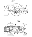
- Fig. 1 eine teilweise dargestellte Futtererntemaschine nach der Erfindung.
- Fig. 2 eine Teildraufsicht auf die Erntemaschine, wobei Teile in gestrichelter Linie wiedergegeben sind.
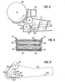
- Fig. 3 in größerem Maßstabe die Zerkleinerungseinrichtung, mit Körnerprozessor und die Zuordnung der Fördereinrichtung.
- Fig. 4 eine Stirnansicht der aus Druckrollen und Fördereinrichtung bestehenden Einheit und
- Fig. 5 eine Seitenansicht der Einheit nach Fig. 4, bei der auch die Antriebsmittel gezeigt sind.
- Fig. 1 is a partially illustrated forage harvesting machine according to the invention.
- Fig. 2 is a partial plan view of the harvesting machine, parts being shown in dashed lines.
- Fig. 3 on a larger scale the crushing device, with grain processor and the assignment of the conveyor.
- Fig. 4 is an end view of the unit consisting of pressure rollers and conveyor and
- Fig. 5 is a side view of the unit of Fig. 4, in which the drive means are also shown.
Die zur Erläuterung der Erfindung verwendete Ausführungsform einer Futtererntemaschine entspricht einer selbstfahrenden Erntemaschine, wie sie in der US-PS 37 01 239 gezeigt ist. Die Erfindung ist selbstverständlich gleichermaßen auf andere Futtererntemaschinen, auch auf solche anwendbar, die durch Ackerschlepper gezogen werden. In der selbstfahrenden Maschine ist ein sich von vorne nach hinten erstreckender Rahmen 10 vorgesehen, der durch vordere und rückwärtige Laufräder 12 und 14 unterstützt ist. Diese werden durch einen Antriebsmotor, z.B. eine Brennkraftmaschine 16,angetrieben. Im dargestellten Fall sind beide Achsen durch hydraulische Einrichtungen 18,20 und 22 und ein Wechselgetriebe 24 für die Vorderräder angetrieben. Hierbei handelt es sich um Einrichtungen, die es in vielen verschiedenen Ausführungsformen gibt und die nicht Teil der vorliegenden Erfindung sind und daher nicht näher beschrieben werden. Bei einer vom Ackerschlepper gezogenen Erntemaschine umfaßt die Kraftquelle ein Getriebe auf dem Rahmen der Erntemaschine, dem die Antriebskraft von der Zapfwelle des Ackerschleppers aus zugeführt wird. Auch diese Einrichtung bildet nicht Teil der vorliegenden Erfindung.The embodiment of a forage harvester used to explain the invention corresponds to a self-propelled harvester as shown in US Pat. No. 3,701,239. The invention is of course equally applicable to other forage harvesters, including those that are pulled by agricultural tractors. In the self-propelled machine, a
Der Rahmen 10 umfaßt einen quer verlaufenden vorderen Tragteil 26. Der hierzu gehörende vordere Bereich trägt eine das Erntegut aufnehmende Einrichtung oder einen Kopf 28, der beliebiger Art und Gestaltung sein kann. Der Erntekopf nimmt das stehende Mais vom Feld in üblicher Weise auf. Das Erntegut wird z. B. durch Zuführungsrollen 30 z.B. in Form von Halmen mit Kolben, Blättern oder dgl. nach rückwärts in Richtung auf eine mit hoher Geschwindigkeit rotierend angetriebene Zerkleinerungseinrichtung 32 gefördert. Diese zylindrische Zerkleinerungseinrichtung arbeitet typischerweise mit einem festen Messer 34 zusammen, um das Erntegut in relativ kleine Abschnitte zu zerkleinern, wie dies üblich ist. Die Zerkleinerungseinrichtung ist hier lediglich vereinfachend als Zylinder gezeigt, wobei die üblichen Messer zur Verdeutlichung weggelassen sind. Das zerkleinerte Gut wird kraftvoll nach unten und rückwärts geschleudert, wenn die Schneideinrichtung in Richtung des eingezeichneten Pfeiles rotiert.The
Bei einer üblichen Ausführungsform einer Erntemaschine wird das zerkleinerte Erntegut normalerweise durch einen nach rückwärts fördernden Förderer zu der Abgabeeinrichtung z.B. einem Gebläse 36 weiterbefördert, das im hinteren Teil der Maschine angeordnet ist. In einer durch einen Ackerschlepper gezogenen Maschine erstreckt sich der Förderer normalerweise quer zur Richtung der Fahrt und das Gebläse befindet sich an einer Seite der Maschine. Dies sind jedoch Einzelheiten, die im vorliegenden Zusammenhang keine besondere Bedeutung haben. Auch kann in einer typischen Futtererntemaschine zum erneuten Zerkleinern ein Sieb direkt hinter der Zerkleinerungseinrichtung in einem tiefer liegenden Teil angebracht werden. Hierbei handelt es sich normalerweise um den Quadranten zwischen der 3 Uhr-Position und der 6 Uhr-Position. Ein solches Sieb kann auch bei der Futtererntemaschine gemäß der Erfindung verwendet werden. So zeigt Fig. 3 gekrümmte Gleitführungen zur Aufnahme eines solchen Siebes bei 38. Es wird nachfolgend ersichtlich, daß die gemäß der Erfindung kombinierten Elemente auch leicht entfernt und durch übliche Mittel ersetzt werden können, worauf ein solches zur weiteren Zerkleinerung dienendes Sieb an Ort und Stelle gebracht wird, wenn dies gewünscht ist.In a conventional embodiment of a harvesting machine, the shredded crop is normally conveyed further by a backward conveyor to the delivery device, for example a
Eine Teilbaueinheit 40 von kastenförmiger Gestalt wird durch den Rahmen der Futtererntemaschine unterstützt und erstreckt sich von einer Stelle unmittelbar hinter und unter der Schneideinrichtung bis zu einem Bereich in der Nachbarschaft des Abgabegebläses 36. Diese Teilbaueinheit und deren Komponenten ersetzen dabei die übliche Fördereinrichtung, die sich zwischen der Schneideinrichtung und dem Gebläse erstreckt. Zu der Teilbaueinheit gehören obere und untere Druckrollen 42, die im entgegengesetzten Sinne gemäß den Pfeilen um quer verlaufende und zueinander parallele Achsen antreibbar sind, die auch parallel zur Drehachse der Schneideinrichtung angeordnet sind. Diese Druckrollen sind auf ihrer Außenfläche gewellt oder gerippt oder geriffelt, wie dies bei Walzenmühlen üblich ist. Sie laufen in unmittelbarer Nähe zueinander, so daß das Erntegut, das von der Schneideinrichtung kommt, weiter zerkleinert wird. Die Druckrollen sind dabei besonders geeignet, Körner oder dergleichen zu zerkleinern. Die Rollen sind so angeordnet, daß die obere Rolle hinter und in einem Bereich unterhalb der Drehachse der Zerkleinerungseinrichtung liegt, während die untere Rolle nach vorne und im wesentlichen nach unten gegenüber der oberen Rolle versetzt ist. Die Lage ist so gewählt, daß die Druckrollen besonders günstig das Erntegut von der Zerkleinerungseinrichtung aufnehmen, ohne daß weitere Fördereinrichtungen notwendig sind. Die Zerkleinerungseinrichtung wirft das Erntegut tangential in einer nach unten und nach rückwärts gerichteten Richtung direkt in den Einlaufspalt zwischen den Druckrollen.A
Die Druckrollen 42 wiederum werfen das weiter zerkleinerte Gut hauptsächlich nach rückwärts, aber ebenfalls nach unten und zwar in den Eingangsteil der von vorne nach hinten fördernden Fördereinrichtung. Diese sind im dargestellten Beispiel durch zwei Förderschnecken 44 (Fig. 4) gebildet. Diese bewegen das zerkleinerte Gut nach rückwärts zum Gebläse 36. Die Wellen der örderer haben eine Reihe von Paddeln 46, um das Erntegut nach der Seite in die Aufnahmeöffnung 48 des seitlichen Gebläsegehäuses zu werfen.The
Die Lage der Rollen in der zuvor beschriebenen Weise, in der die untere Rolle gegenüber der oberen Rolle nach vorne und nach unten versetzt ist, ermöglicht es, daß der vordere Teil der Fördereinrichtung möglichst nahe den Rollen zu liegen kommt, und zwar in einem Bereich, wo die vorderen Enden der Förderelemente bei 50 in einer Querwand 52 der Teilbaueinheit gelagert sind. Die örderer oder Schnecken sind kürzer als die ersetzten Fördereinrichtungen der üblichen Futtererntemaschine ' um einen Betrag, der notwendig ist, um die Druckrollen aufzunehmen. D.ies erleichtert das Auswechseln der Teilbaueinheit gegen einen üblichen Förderer.The position of the rollers in the manner described above, in which the lower roller is offset forwards and downwards relative to the upper roller, enables the front part of the conveyor to come as close as possible to the rollers, in an area where the front ends of the conveyor elements are mounted at 50 in a
Das Montieren der kastenförmigen Teilbaueinheit 40 kann am besten aus den Fig. 1 und 4 erkannt werden. Jedes Glied des Rahmens 10 weist vordere und rückwärtige nach unten ragende Tragglieder auf. Diese erstrecken sich an der Längsseite beiderseits der Teilbaueinheit. Jedes Tragglied ist an der zugehörigen Seitenwand der Teilbaueinheit mit Hilfe von lösbaren Stiften 62 befestigt. Die zugehörigen Öffnungen in der Wand sind bei 64 in Fig. 5 zu sehen.The mounting of the box-shaped
In einer bevorzugten Ausführungsform sind die Durchmesser der Rollen 42 so gewählt, daß sie etwa 1/3 des Durchmessers der zylinderförmigen Schneideinrichtung aufweisen. Im dargestellten Beispiel beträgt der Durchmesser der Rollen 20 cm und der der Zerkleinerungseinrichtung 60 cm. Die Drehgeschwindigkeit der unteren Rolle 42 ist größer als die der oberen Rolle, um eine Anhäufung des behandelten Erntegutes insb. von Kernen zu vermeiden. Weiterhin wurden gute Ergebnisse erhalten, wenn die Oberflächengeschwindigkeit der unteren Rolle annähernd gleich der tangentialen Geschwindigkeit der Zerkleinerungseinrichtung ist. Im dargestellten Beispiel beträgt die Rotationsgeschwindigkeit der Zerkleinerungseinrichtung etwa 850 U/min., während die langsame Rolle mit 2250 und die schnellere Rolle mit 2750 U/min. angetrieben werden. Als Beispiel dienende Antriebsmittel zur Erzielung der gezeigten Drehzahlen wird auf die Figuren 2 und 5 verwiesen. Wie aus Fig. 2 hervorgeht, weist die Antriebsmaschine 16 eine Antriebswelle 70 auf, die mit Hilfe eines Kegelrades 72 eine Querwelle 74 antreibt, auf der die Flügel des Gebläses 36 montiert sind. Ein Antriebsriemen 76 verbindet diese Welle mit der Welle der Zerkleinerungseinrichtung. Ein Flachriemen oder ein Mehrfach-V-Riemen 78 treibt die obere Druckrolle 42 an. An der entgegengesetzten Seite der Maschine ist ein Differentialantrieb vorgesehen, der die untere Rolle antreibt sowie eine Querwelle 80 für die Förderschnecken. Dieser Antrieb umfaßt eine Riemenscheibe 82 auf der Welle der oberen Rolle, eine Riemenscheibe 84 auf der Welle für die untere Druckrolle, eine Riemenscheibe 86 auf der Querwelle 80, eine leer umlaufende Riemenscheibe 88 sowie einen mehrfachen V-Riemen 90 auf, der um die Riemenscheibe in einer solchen Weise gelegt ist, daß die unteren und oberen Druckrollen in entgegengesetzten Richtungen rotieren. Ein Kegeltrieb 92 vervollständigt den Antrieb für die Schnecken 44. Die Aufsammeleinrichtung und die Zuführungsrollen 30 können in irgend einer passenden Weise angetrieben werden. Einzelheiten hierüber sind weggelassen, da sie nicht Teil der Erfindung sind.In a preferred embodiment, the diameters of the
Die untere Druckrolle kann Mittel haben, um ihre Stellung gegenüber der oberen Rolle einstellen zu können. Sie umfaßt vorzugsweise nachgiebige Mittel, so daß die Druckrollen sich auseinander bewegen können, wenn Fremdkörper vorliegen, wie dies aus Walzenmühlen bekannt ist. Die Vorteile dieser Mühlen als solche sind ebenfalls bekannt und brauchen hier nicht detailliert auseinandergesetzt zu werden. Ein Vorteil jedoch besteht darin, daß die Walzenmühle in ihrer Anordnung in einer Futtererntemaschine den Nachteil der Notwendigkeit vermeidet, zur zusätzlichen Zerkleinerung dienende Siebe oder dergleichen zu verwenden. Die Walzen sind auch wirkungsvoller als solche Siebe, wobei die Siebe das ganze Material zu kleinen Partikelchen zerkleinern. Ein anderer ! Vorteil besteht darin, daß die Druckrollen weniger Abrieb erzeugen, was zu Verdauungsproblemen führt und die Verwendung des Futters einschränkt. Grobe Partikelchen werden auf eßbare Größe vermindert und die Silage als Ganzes ist gleichförmiger bezüglich der Teilchenlänge, so daß eine bessere Packung in einem Silo oder dgl. erreicht wird. Die Druckrollen sind besonders vorteilhaft bei Verminderung später geernteter Maisfutterteile, bei denen die härteren Kerne bei früheren Systemen der Zerkleinerung entgegen. Dabei sorgen die Druckrollen für eine Konsistenz des Futters, daß auch von älteren Kühen mit abgenutzten Zähnen besser angenommen wird.The lower pressure roller can have means to adjust its position in relation to the upper roller. It preferably comprises resilient means so that the pressure rollers can move apart when there are foreign bodies, as is known from roller mills. The advantages of these mills as such are also known and need not be discussed in detail here. An advantage, however, is that the roller mill, when it is arranged in a forage harvester, avoids the disadvantage of the need to use screens or the like for additional comminution. The rollers are also more effective than such screens, with the screens crushing the entire material into small particles. Another ! The advantage is that the pressure rollers produce less abrasion, which leads to digestive problems and limits the use of the feed. Coarse particles are reduced to an edible size and the silage as a whole is more uniform in particle length, so that better packing in a silo or the like is achieved. The pressure rollers are particularly advantageous in reducing later harvested maize feed parts, in which the harder kernels in earlier cereal systems contraction. The pressure rollers ensure the consistency of the feed so that older cows with worn teeth are better accepted.
Claims (20)
Applications Claiming Priority (2)
| Application Number | Priority Date | Filing Date | Title |
|---|---|---|---|
| US06/235,314 US4345417A (en) | 1981-02-17 | 1981-02-17 | Forage harvester with kernel processing means |
| US235314 | 1981-02-17 |
Related Parent Applications (1)
| Application Number | Title | Priority Date | Filing Date |
|---|---|---|---|
| EP82101139.2 Division | 1982-02-16 |
Publications (1)
| Publication Number | Publication Date |
|---|---|
| EP0127747A1 true EP0127747A1 (en) | 1984-12-12 |
Family
ID=22884984
Family Applications (2)
| Application Number | Title | Priority Date | Filing Date |
|---|---|---|---|
| EP84103863A Withdrawn EP0127747A1 (en) | 1981-02-17 | 1982-02-16 | Forage harvesting machine |
| EP82101139A Expired EP0058431B1 (en) | 1981-02-17 | 1982-02-16 | Forage harvesting machine |
Family Applications After (1)
| Application Number | Title | Priority Date | Filing Date |
|---|---|---|---|
| EP82101139A Expired EP0058431B1 (en) | 1981-02-17 | 1982-02-16 | Forage harvesting machine |
Country Status (6)
| Country | Link |
|---|---|
| US (1) | US4345417A (en) |
| EP (2) | EP0127747A1 (en) |
| CA (1) | CA1166853A (en) |
| DE (1) | DE3278454D1 (en) |
| DK (1) | DK148612C (en) |
| ES (1) | ES509626A0 (en) |
Cited By (2)
| Publication number | Priority date | Publication date | Assignee | Title |
|---|---|---|---|---|
| KR100858860B1 (en) * | 2000-04-10 | 2008-09-17 | 다카라 바이오 가부시키가이샤 | A food, feed, beverage and composition for enhancing nerve growth factor production |
| CN106416599A (en) * | 2016-08-31 | 2017-02-22 | 平阳县凯达包装机械厂 | Twin-screw compression straw baler |
Families Citing this family (23)
| Publication number | Priority date | Publication date | Assignee | Title |
|---|---|---|---|---|
| IT1194480B (en) * | 1982-11-27 | 1988-09-22 | Mengele & Soehne Masch Karl | Feed cutting |
| DE3245706A1 (en) * | 1982-12-10 | 1984-06-14 | Karl Mengele & Söhne Maschinenfabrik und Eisengießerei GmbH & Co, 8870 Günzburg | Field, mowing or picking chopper |
| DE3337381C2 (en) * | 1983-10-14 | 1994-07-21 | Claas Ohg | Forage harvester |
| DD220802A1 (en) * | 1984-02-08 | 1985-04-10 | Fortschritt Veb K | DRUM HOLDER WITH A NACHZERKLEINERUNGSEINICHTICHT |
| DE3407333A1 (en) * | 1984-02-29 | 1985-08-29 | Claas Ohg, 4834 Harsewinkel | Field chopper |
| DE3415508A1 (en) * | 1984-04-26 | 1985-11-07 | Karl Mengele & Söhne Maschinenfabrik und Eisengießerei GmbH & Co, 8870 Günzburg | FIELD CHOPPER |
| DE3417314C2 (en) * | 1984-05-10 | 1986-08-21 | Maschinenfabrik Kemper Gmbh, 4424 Stadtlohn | Chopper |
| US4617786A (en) * | 1984-08-15 | 1986-10-21 | Hesston Corporation | Forage harvester having supplemental crop disintegrating means |
| US4678129A (en) * | 1986-04-09 | 1987-07-07 | New Holland Inc. | Paddle wheel assembly for forage harvesters |
| US5822962A (en) * | 1996-04-26 | 1998-10-20 | New Holland North America, Inc. | Crop processor apparatus for pull-type forage harvester |
| US6116529A (en) * | 1998-04-15 | 2000-09-12 | Fisher, Jr.; Gideon A. | Corn processor for forage harvester |
| US6125617A (en) * | 1998-09-15 | 2000-10-03 | Gehl Company | Cut crop processing mechanism for a forage harvester incorporating a pivotable auger |
| US6131837A (en) * | 1999-07-28 | 2000-10-17 | New Holland North America, Inc. | Segmented crop processor roll for forage harvester |
| TW498664B (en) * | 1999-09-17 | 2002-08-11 | Qualcomm Inc | Method and apparatus for rotating a phase of a modulated signal |
| GB9930743D0 (en) * | 1999-12-29 | 2000-02-16 | Ford New Holland Nv | Crop processor roll arrangement for a forage harvester |
| DE102004034849B4 (en) * | 2004-07-19 | 2006-06-01 | Peter Kölln KGaA | Process for preparing oat hulls for xylan recovery |
| DE102007045373A1 (en) * | 2007-09-22 | 2009-04-02 | Cemag Anlagenbau Gmbh | Method and device for pre- and final grinding of mineral and non-mineral materials |
| DE102010002343A1 (en) * | 2010-02-25 | 2011-08-25 | Deere & Company, Ill. | Forage harvester with a chopper and a post-processing device arranged downstream of the chopper |
| US9486806B1 (en) | 2011-04-01 | 2016-11-08 | Claas Saulgau Gmbh | System and method for processing crop materials into livestock feed and the product thereof |
| US9185844B2 (en) | 2013-10-01 | 2015-11-17 | Cnh Industrial America Llc | Feeding mechanism of a header for a combine harvester |
| CN103931340A (en) * | 2014-04-15 | 2014-07-23 | 满金海 | Corncob picking device of corn harvester |
| US11191218B1 (en) * | 2016-10-27 | 2021-12-07 | Ethen D Wentz | Bale shredder with elevated discharge |
| CN108184456A (en) * | 2018-03-05 | 2018-06-22 | 连云港励尚信息科技有限公司 | A kind of environment-friendly type stalk quick-rotary type reducing mechanism |
Citations (3)
| Publication number | Priority date | Publication date | Assignee | Title |
|---|---|---|---|---|
| US3349823A (en) * | 1964-07-15 | 1967-10-31 | Avco Corp | Corn grinder for field operation |
| DE2443780A1 (en) * | 1973-09-14 | 1975-03-20 | Egidio Pecis | DEVICE FOR PROCESSING GRAIN ETC. TO FODDER |
| DE3000946A1 (en) * | 1979-01-15 | 1980-07-24 | Revere Corp Paul | CATTLE FEEDING MACHINE WITH PINCH ROLLERS |
Family Cites Families (13)
| Publication number | Priority date | Publication date | Assignee | Title |
|---|---|---|---|---|
| US290571A (en) * | 1883-12-18 | Method of reducing corn in the stalk and separating the kernels | ||
| US2540264A (en) * | 1943-12-27 | 1951-02-06 | Int Harvester Co | Ensilage harvester having twin roller feed |
| US3023560A (en) * | 1959-06-09 | 1962-03-06 | Ford Motor Co | Forage harvester |
| US3357164A (en) * | 1965-05-12 | 1967-12-12 | Deere & Co | Forage harvester |
| US3513646A (en) * | 1967-11-13 | 1970-05-26 | Int Harvester Co | Combination harvesting and threshing machine |
| US3680291A (en) * | 1969-11-10 | 1972-08-01 | Deere & Co | Corn harvesting machine |
| DE1962777A1 (en) * | 1969-12-15 | 1971-06-24 | Nordenskjoeld Reinhard Von Dip | Process for preparing harvestable leaves or stalks for ensiling or drying and facilities for carrying out the process |
| BE789983A (en) * | 1971-10-12 | 1973-02-01 | Deere & Co | CONTROL DEVICE FOR AN AUTOMOTIVE FIELD CHOPPER |
| US3933314A (en) * | 1973-02-12 | 1976-01-20 | Art Luscombe | Chopping implement |
| US3916605A (en) * | 1974-02-05 | 1975-11-04 | Avco Corp | Forage harvester with improved flow pattern for cut material |
| US3913303A (en) * | 1974-03-04 | 1975-10-21 | Avco Corp | Feed roll construction for forage harvester |
| US4245948A (en) * | 1979-01-12 | 1981-01-20 | Bernard Kersten | Corn shelling attachment for combines |
| FR2455852A1 (en) * | 1979-05-09 | 1980-12-05 | Le Gall Pierre | Combined silage maize harvester and crusher - has toothed steel cylinder or sheet metal grater with teeth in cutting chamber to increases fineness |
-
1981
- 1981-02-17 US US06/235,314 patent/US4345417A/en not_active Expired - Lifetime
-
1982
- 1982-02-03 CA CA000395457A patent/CA1166853A/en not_active Expired
- 1982-02-16 DE DE8282101139T patent/DE3278454D1/en not_active Expired
- 1982-02-16 ES ES509626A patent/ES509626A0/en active Granted
- 1982-02-16 EP EP84103863A patent/EP0127747A1/en not_active Withdrawn
- 1982-02-16 EP EP82101139A patent/EP0058431B1/en not_active Expired
- 1982-02-17 DK DK68782A patent/DK148612C/en not_active IP Right Cessation
Patent Citations (3)
| Publication number | Priority date | Publication date | Assignee | Title |
|---|---|---|---|---|
| US3349823A (en) * | 1964-07-15 | 1967-10-31 | Avco Corp | Corn grinder for field operation |
| DE2443780A1 (en) * | 1973-09-14 | 1975-03-20 | Egidio Pecis | DEVICE FOR PROCESSING GRAIN ETC. TO FODDER |
| DE3000946A1 (en) * | 1979-01-15 | 1980-07-24 | Revere Corp Paul | CATTLE FEEDING MACHINE WITH PINCH ROLLERS |
Cited By (3)
| Publication number | Priority date | Publication date | Assignee | Title |
|---|---|---|---|---|
| KR100858860B1 (en) * | 2000-04-10 | 2008-09-17 | 다카라 바이오 가부시키가이샤 | A food, feed, beverage and composition for enhancing nerve growth factor production |
| CN106416599A (en) * | 2016-08-31 | 2017-02-22 | 平阳县凯达包装机械厂 | Twin-screw compression straw baler |
| CN106416599B (en) * | 2016-08-31 | 2019-04-19 | 平阳县凯达包装机械厂 | Twin-screw compresses straw baler |
Also Published As
| Publication number | Publication date |
|---|---|
| EP0058431A1 (en) | 1982-08-25 |
| EP0058431B1 (en) | 1988-05-11 |
| DK148612B (en) | 1985-08-19 |
| US4345417A (en) | 1982-08-24 |
| CA1166853A (en) | 1984-05-08 |
| DK148612C (en) | 1986-04-28 |
| DK68782A (en) | 1982-08-18 |
| DE3278454D1 (en) | 1988-06-16 |
| ES8303008A1 (en) | 1983-02-01 |
| ES509626A0 (en) | 1983-02-01 |
Similar Documents
| Publication | Publication Date | Title |
|---|---|---|
| EP0127747A1 (en) | Forage harvesting machine | |
| DE3302980C2 (en) | ||
| DE60033448T2 (en) | Harvest processing unit and blower arrangement for a forage harvester | |
| EP1106047A1 (en) | Corn gathering and picking device and harvesting machine | |
| EP0960561A1 (en) | Crop chopper | |
| DE3011089A1 (en) | FIELD CHOPPER | |
| DE1189777B (en) | Flail chopper | |
| DE19753486B4 (en) | chopping | |
| EP0917819A1 (en) | Combine with a staw chopper | |
| EP0153621B1 (en) | Drum chopper with a recomminution device | |
| DD298037A5 (en) | HAMKSLER FOR THE CRUSHING OF HALF-FORMAL RESOURCE | |
| DE4332430C2 (en) | Mowing machine, in particular lawn mower | |
| DD220803A1 (en) | NACHZERKLEINERUNGSEINICHTUNG FOR HAECKSELGUT | |
| DE3245706C2 (en) | ||
| DE2433657A1 (en) | SCRAP BLOWERS FOR LITTLE GOODS, IN PARTICULAR CORES | |
| DE2621292A1 (en) | Maize harvester cutter assembly - has contra-rotating rotors with toothed wheels having overlapping sections | |
| DE2422894A1 (en) | Forage harvester with transverse conveyor - has conveyor joined tangentially to inlet-duct connected to casing | |
| DE3316241A1 (en) | Maize chopper having a friction floor | |
| EP1101397A1 (en) | Conditioning device for forage harvester | |
| DE2352167C3 (en) | Single-row mounted lV viscous piston grinder | |
| DE2406275C2 (en) | Forage harvester | |
| EP0643906A1 (en) | Harvester, especially combine harvester, equipped with a conditioning device at the rear end | |
| DE3324898A1 (en) | Cutting and feeding device for a drawn machine or a machine provided for three-point mounting on the tractor, for the harvesting of maize or suchlike stalk crops | |
| DE2627096A1 (en) | COMBINED HARVESTING MACHINE FOR THRESHING OR THRESHING AND SCRAPING CORN COBS | |
| AT310569B (en) | Forage wagon forage harvesters |
Legal Events
| Date | Code | Title | Description |
|---|---|---|---|
| PUAI | Public reference made under article 153(3) epc to a published international application that has entered the european phase |
Free format text: ORIGINAL CODE: 0009012 |
|
| 17P | Request for examination filed |
Effective date: 19840417 |
|
| AC | Divisional application: reference to earlier application |
Ref document number: 58431 Country of ref document: EP |
|
| AK | Designated contracting states |
Designated state(s): DE FR GB IT NL |
|
| ITCL | It: translation for ep claims filed |
Representative=s name: LENZI & C. |
|
| TCNL | Nl: translation of patent claims filed | ||
| EL | Fr: translation of claims filed | ||
| 17Q | First examination report despatched |
Effective date: 19860226 |
|
| STAA | Information on the status of an ep patent application or granted ep patent |
Free format text: STATUS: THE APPLICATION HAS BEEN WITHDRAWN |
|
| 18W | Application withdrawn |
Withdrawal date: 19870120 |
|
| RIN1 | Information on inventor provided before grant (corrected) |
Inventor name: SCHMID, STEVEN LAWRENCE Inventor name: BOOKER, WALTER WOODROW Inventor name: DE BUHR, HAROLD EUGENE |