EP0127700A1 - Production of apertures in flowing material - Google Patents
Production of apertures in flowing material Download PDFInfo
- Publication number
- EP0127700A1 EP0127700A1 EP83200761A EP83200761A EP0127700A1 EP 0127700 A1 EP0127700 A1 EP 0127700A1 EP 83200761 A EP83200761 A EP 83200761A EP 83200761 A EP83200761 A EP 83200761A EP 0127700 A1 EP0127700 A1 EP 0127700A1
- Authority
- EP
- European Patent Office
- Prior art keywords
- parts
- shuttering
- boundary
- wedge
- opening
- Prior art date
- Legal status (The legal status is an assumption and is not a legal conclusion. Google has not performed a legal analysis and makes no representation as to the accuracy of the status listed.)
- Withdrawn
Links
Images


Classifications
-
- E—FIXED CONSTRUCTIONS
- E04—BUILDING
- E04G—SCAFFOLDING; FORMS; SHUTTERING; BUILDING IMPLEMENTS OR AIDS, OR THEIR USE; HANDLING BUILDING MATERIALS ON THE SITE; REPAIRING, BREAKING-UP OR OTHER WORK ON EXISTING BUILDINGS
- E04G15/00—Forms or shutterings for making openings, cavities, slits, or channels
- E04G15/02—Forms or shutterings for making openings, cavities, slits, or channels for windows, doors, or the like
Abstract
Description
Die Erfindung beschreibt ein Verfahren zur Herstellung von öffnungen. Dabei können die Öffnungen eine beliebige Geometrie haben. Weiterhin können ein- oder zweischalige Bauelemente durch die Erfindung mit Öffnungen versehen werden.The invention describes a method for producing openings. The openings can have any geometry. Furthermore, single- or double-shell components can be provided with openings by the invention.
Die Herstellung von Öffnungen bezieht sich auf fließendes Material, das in eine beliebig geartete SChalung eingegossen wird und eine öffnungsbegrenzung in zwei Ebenen darstellt.The production of openings refers to flowing material that is poured into any type of shuttering and represents an opening limitation in two levels.
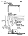
Hierzu wird beliebiges Begrenzungsmaterial nach Fig. 1 und 2 benötigt (1). Bei Herstellung von zweischaligen Elementen kann das Begrenzungsteil (1) unterbrochen werden. Bei größeren öffnungen ist zur Aufnahme des Seitendruckes eine Aussteifung erforderlich (3) und eine Aufdoppelung (4), die jeweils den Schalungsboden berührt. Die Erfindung des Verfahrens betrifft die Festhaltung der Begrenzungsteile und bei Herstellung von zweischaligen Elementen eine Abgrenzung des gegossenen Materials nach der Innenseite hin.Any boundary material according to FIGS. 1 and 2 is required for this (1). When producing double-shell elements, the limiting part (1) can be interrupted. In the case of larger openings, bracing is required to accommodate the side pressure (3) and a doubling (4), each of which touches the formwork floor. The invention of the method relates to the retention of the delimiting parts and, in the production of double-shell elements, a delimitation of the cast material towards the inside.
Die Begrenzung der Eckpunkte, die unter einem beliebigen Winkel erfolgen kann, geschieht durch einen an der Außenkante liegenden Winkel, der durch eine diagonal liegende Schraube gehalten wird und auf der Innenseite durch eine Dreieckleiste (9), die aufgesteckt wird und hierzu einen Schlitz hat, bewirkt, daß die Begrenzungsteile paßgenau aneinandergepreßt werden. Auf die Dreieckleiste wird eine geschlitzte Keilscheibe aufgesteckt, die erst nach Anziehen von zwei Kontermuttern (7) eingeschlagen wird. Diese Keilscheibe (8) bewirkt die kraftschlüssige Verbindung der Begrenzungsteile. Diese Verbindung bewirkt, daß die Begrenzungsteile an einem dritten Ort hergestellt werden können und nach Bedarf in die Hauptschalung eingelegt werden können.The corner points, which can be at any angle, are delimited by an angle on the outer edge, which is held by a diagonally positioned screw, and on the inside by a triangular strip (9), which is attached and has a slot for this purpose. causes the boundary parts to be pressed together with a precise fit. A slotted wedge washer is placed on the triangular strip, which is only driven in after two lock nuts (7) have been tightened. This wedge disc (8) brings about the non-positive connection of the limiting parts. This connection means that the boundary parts can be made at a third location and can be inserted into the main formwork as required.
Für den Fall, daß die Begrenzungsteile nicht im Bauteil verbleiben, wird ein Schenkel der Begrenzungsteile an der Verbindungsecke derart geschlitzt, daß nach Herausschlagen der Keilscheibe(8) der Bolzen in diesem Schlitz derart bewegt wird, daß der andere Schenkel des Begrenzungsteiles durch eine Drehbewegung in Richtung des gekippten Bolzens (6) ausgebaut werden kann.In the event that the boundary parts do not remain in the component, one leg of the boundary parts is slotted at the connecting corner in such a way that after knocking out the wedge disc (8) the bolt is moved in this slot in such a way that the other leg of the boundary part is rotated can be removed in the direction of the tilted bolt (6).
Bei Herstellung von zwei- oder mehrschaligen Bauelementen ist es nach der Erfindung erforderlich, eine innere Begrenzung des fließenden Materiales zur Innenseite zu haben. Hierzu wird nach Fig. 5 eine innere Begrenzungsplatte (11) eingebaut, die ein Ausfließen des gegossenen Materials verhindert.When producing two- or multi-layer components, it is necessary according to the invention to have an inner boundary of the flowing material on the inside. For this purpose, an inner boundary plate (11) is installed according to FIG. 5, which prevents the cast material from flowing out.
Die innere Begrenzungsplatte kann auch ein Netz aus beliebigem Material sein, das die gleiche Aufgabe erfüllt. Die Begrenzung muß nicht eben sein.The inner boundary plate can also be a network of any material that does the same job. The limitation does not have to be flat.
Für den Fall einer wiedergewonnen Begrenzungsfläche ist es erforderlich, sogenannte Abstandshalter (13) einzubauen, die dann an einem inneren Traggerüst befestigt werden. Diese Abstandshalter und das Traggerüst können auch fehlen.In the case of a regained boundary surface, it is necessary to install so-called spacers (13), which are then attached to an inner supporting structure. These spacers and the supporting structure can also be missing.
Claims (9)
Priority Applications (1)
| Application Number | Priority Date | Filing Date | Title |
|---|---|---|---|
| EP83200761A EP0127700A1 (en) | 1983-05-30 | 1983-05-30 | Production of apertures in flowing material |
Applications Claiming Priority (1)
| Application Number | Priority Date | Filing Date | Title |
|---|---|---|---|
| EP83200761A EP0127700A1 (en) | 1983-05-30 | 1983-05-30 | Production of apertures in flowing material |
Publications (1)
| Publication Number | Publication Date |
|---|---|
| EP0127700A1 true EP0127700A1 (en) | 1984-12-12 |
Family
ID=8190957
Family Applications (1)
| Application Number | Title | Priority Date | Filing Date |
|---|---|---|---|
| EP83200761A Withdrawn EP0127700A1 (en) | 1983-05-30 | 1983-05-30 | Production of apertures in flowing material |
Country Status (1)
| Country | Link |
|---|---|
| EP (1) | EP0127700A1 (en) |
Cited By (2)
| Publication number | Priority date | Publication date | Assignee | Title |
|---|---|---|---|---|
| US6550194B2 (en) * | 1999-01-15 | 2003-04-22 | Feather Lite Innovations, Inc. | Window buck system for concrete walls and method of installing a window |
| US7490442B1 (en) | 2004-07-27 | 2009-02-17 | Feather Lite Innovations, Inc. | Window system for concrete walls and associated method |
Citations (5)
| Publication number | Priority date | Publication date | Assignee | Title |
|---|---|---|---|---|
| US1791645A (en) * | 1928-03-23 | 1931-02-10 | E W Sproul Construction Compan | Concrete building construction |
| FR1464832A (en) * | 1965-11-16 | 1967-01-06 | Improvements to formwork for doors, windows or the like | |
| FR2067453A5 (en) * | 1969-11-04 | 1971-08-20 | Dormoy Henri | |
| FR2313522A1 (en) * | 1975-06-07 | 1976-12-31 | Dexler Heinz Kg | CORNER ASSEMBLY ELEMENT FOR REMOVABLE AND REUSABLE FORMWORK |
| DE2840548A1 (en) * | 1978-09-18 | 1980-03-20 | Wolfgang Baumann | Temporary wall or ceiling aperture enclosure frame - comprises several metal rectangular elements detachably joined in tandem forming rigid entity |
-
1983
- 1983-05-30 EP EP83200761A patent/EP0127700A1/en not_active Withdrawn
Patent Citations (5)
| Publication number | Priority date | Publication date | Assignee | Title |
|---|---|---|---|---|
| US1791645A (en) * | 1928-03-23 | 1931-02-10 | E W Sproul Construction Compan | Concrete building construction |
| FR1464832A (en) * | 1965-11-16 | 1967-01-06 | Improvements to formwork for doors, windows or the like | |
| FR2067453A5 (en) * | 1969-11-04 | 1971-08-20 | Dormoy Henri | |
| FR2313522A1 (en) * | 1975-06-07 | 1976-12-31 | Dexler Heinz Kg | CORNER ASSEMBLY ELEMENT FOR REMOVABLE AND REUSABLE FORMWORK |
| DE2840548A1 (en) * | 1978-09-18 | 1980-03-20 | Wolfgang Baumann | Temporary wall or ceiling aperture enclosure frame - comprises several metal rectangular elements detachably joined in tandem forming rigid entity |
Cited By (2)
| Publication number | Priority date | Publication date | Assignee | Title |
|---|---|---|---|---|
| US6550194B2 (en) * | 1999-01-15 | 2003-04-22 | Feather Lite Innovations, Inc. | Window buck system for concrete walls and method of installing a window |
| US7490442B1 (en) | 2004-07-27 | 2009-02-17 | Feather Lite Innovations, Inc. | Window system for concrete walls and associated method |
Similar Documents
| Publication | Publication Date | Title |
|---|---|---|
| DE2601486C3 (en) | ||
| US4418884A (en) | Double-hinge corner for a concrete forming structure | |
| EP0127700A1 (en) | Production of apertures in flowing material | |
| DE2843109A1 (en) | METHOD OF MANUFACTURING SLIDERS OF LOCKING DEVICES | |
| DE3403459A1 (en) | METHOD FOR PRODUCING TOOLS FOR DEVICES FOR LAYING RAILWAY RAILS, AND TOOL PRODUCED THEREFORE | |
| EP0659949A1 (en) | Manhole element and process for making concrete elements, in particular manhole elements | |
| DE3911606A1 (en) | Shuttering for concrete structure - has panels supported by corner elements made from two angle pieces | |
| DE2748083C2 (en) | Device for the assembly and support of planar components | |
| DE2330586A1 (en) | Internal corner for shuttering assembly - consists of profiled steel corner clamped against adjacent shuttering elements | |
| DE2017448A1 (en) | Device for boarding | |
| AT309349B (en) | Container, shaft or the like., In particular for sewage systems | |
| DE19546184A1 (en) | Device for temporarily positioning a frame to be firmly connected to a concrete wall during the manufacture of the concrete wall | |
| DE2333056A1 (en) | Detachable horizontal base-cavity section - between two concreting forms and consists of two truncated cone-shaped parts | |
| AT92464B (en) | Form for the production of cash cabinets or the like made of reinforced concrete. | |
| DE19800569C2 (en) | Formwork system for a reinforcement connection | |
| DE1964275A1 (en) | Method of making split molds | |
| AT52728B (en) | Device for molding and casting houses and the like in one piece. | |
| DE102006034512B4 (en) | Monolithic pipe elbow for large pipes and process for its production | |
| DE2402338B2 (en) | COAT FILLER WALL | |
| DE364153C (en) | Method and mold for pouring concrete cash cabinets | |
| DE2318750A1 (en) | INTERNAL CORNER FORMWORK ELEMENT | |
| DE1290468B (en) | Form for the production of concrete panels in a horizontal position | |
| DE2918362C2 (en) | Method for producing a watertight and corrosion-resistant connection | |
| WO2000019018A1 (en) | Bearing for the base point of a steel bridge and method for producing the same | |
| DE4242471A1 (en) | Combined shuttering for water-tight working and expansion joints in concrete |
Legal Events
| Date | Code | Title | Description |
|---|---|---|---|
| PUAI | Public reference made under article 153(3) epc to a published international application that has entered the european phase |
Free format text: ORIGINAL CODE: 0009012 |
|
| AK | Designated contracting states |
Designated state(s): AT BE CH DE FR GB IT LI LU NL SE |
|
| 17P | Request for examination filed |
Effective date: 19850218 |
|
| STAA | Information on the status of an ep patent application or granted ep patent |
Free format text: STATUS: THE APPLICATION IS DEEMED TO BE WITHDRAWN |
|
| 18D | Application deemed to be withdrawn |
Effective date: 19870613 |