EP0127339B1 - Bremssystem mit Schrittmotor - Google Patents
Bremssystem mit Schrittmotor Download PDFInfo
- Publication number
- EP0127339B1 EP0127339B1 EP84302942A EP84302942A EP0127339B1 EP 0127339 B1 EP0127339 B1 EP 0127339B1 EP 84302942 A EP84302942 A EP 84302942A EP 84302942 A EP84302942 A EP 84302942A EP 0127339 B1 EP0127339 B1 EP 0127339B1
- Authority
- EP
- European Patent Office
- Prior art keywords
- valve
- brake system
- stepping motor
- pneumatic
- nut
- Prior art date
- Legal status (The legal status is an assumption and is not a legal conclusion. Google has not performed a legal analysis and makes no representation as to the accuracy of the status listed.)
- Expired
Links
- 230000001419 dependent effect Effects 0.000 claims description 4
- 230000000694 effects Effects 0.000 claims description 2
- XEEYBQQBJWHFJM-UHFFFAOYSA-N Iron Chemical compound [Fe] XEEYBQQBJWHFJM-UHFFFAOYSA-N 0.000 description 2
- 230000003044 adaptive effect Effects 0.000 description 2
- 239000000203 mixture Substances 0.000 description 2
- 230000036461 convulsion Effects 0.000 description 1
- 238000010586 diagram Methods 0.000 description 1
- 229910052742 iron Inorganic materials 0.000 description 1
- 238000002156 mixing Methods 0.000 description 1
- 238000009877 rendering Methods 0.000 description 1
Images

Classifications
-
- B—PERFORMING OPERATIONS; TRANSPORTING
- B60—VEHICLES IN GENERAL
- B60T—VEHICLE BRAKE CONTROL SYSTEMS OR PARTS THEREOF; BRAKE CONTROL SYSTEMS OR PARTS THEREOF, IN GENERAL; ARRANGEMENT OF BRAKING ELEMENTS ON VEHICLES IN GENERAL; PORTABLE DEVICES FOR PREVENTING UNWANTED MOVEMENT OF VEHICLES; VEHICLE MODIFICATIONS TO FACILITATE COOLING OF BRAKES
- B60T13/00—Transmitting braking action from initiating means to ultimate brake actuator with power assistance or drive; Brake systems incorporating such transmitting means, e.g. air-pressure brake systems
- B60T13/10—Transmitting braking action from initiating means to ultimate brake actuator with power assistance or drive; Brake systems incorporating such transmitting means, e.g. air-pressure brake systems with fluid assistance, drive, or release
- B60T13/66—Electrical control in fluid-pressure brake systems
- B60T13/68—Electrical control in fluid-pressure brake systems by electrically-controlled valves
-
- B—PERFORMING OPERATIONS; TRANSPORTING
- B60—VEHICLES IN GENERAL
- B60T—VEHICLE BRAKE CONTROL SYSTEMS OR PARTS THEREOF; BRAKE CONTROL SYSTEMS OR PARTS THEREOF, IN GENERAL; ARRANGEMENT OF BRAKING ELEMENTS ON VEHICLES IN GENERAL; PORTABLE DEVICES FOR PREVENTING UNWANTED MOVEMENT OF VEHICLES; VEHICLE MODIFICATIONS TO FACILITATE COOLING OF BRAKES
- B60T13/00—Transmitting braking action from initiating means to ultimate brake actuator with power assistance or drive; Brake systems incorporating such transmitting means, e.g. air-pressure brake systems
- B60T13/10—Transmitting braking action from initiating means to ultimate brake actuator with power assistance or drive; Brake systems incorporating such transmitting means, e.g. air-pressure brake systems with fluid assistance, drive, or release
- B60T13/66—Electrical control in fluid-pressure brake systems
- B60T13/665—Electrical control in fluid-pressure brake systems the systems being specially adapted for transferring two or more command signals, e.g. railway systems
-
- B—PERFORMING OPERATIONS; TRANSPORTING
- B60—VEHICLES IN GENERAL
- B60T—VEHICLE BRAKE CONTROL SYSTEMS OR PARTS THEREOF; BRAKE CONTROL SYSTEMS OR PARTS THEREOF, IN GENERAL; ARRANGEMENT OF BRAKING ELEMENTS ON VEHICLES IN GENERAL; PORTABLE DEVICES FOR PREVENTING UNWANTED MOVEMENT OF VEHICLES; VEHICLE MODIFICATIONS TO FACILITATE COOLING OF BRAKES
- B60T8/00—Arrangements for adjusting wheel-braking force to meet varying vehicular or ground-surface conditions, e.g. limiting or varying distribution of braking force
- B60T8/18—Arrangements for adjusting wheel-braking force to meet varying vehicular or ground-surface conditions, e.g. limiting or varying distribution of braking force responsive to vehicle weight or load, e.g. load distribution
- B60T8/1893—Arrangements for adjusting wheel-braking force to meet varying vehicular or ground-surface conditions, e.g. limiting or varying distribution of braking force responsive to vehicle weight or load, e.g. load distribution especially adapted for railway vehicles
-
- B—PERFORMING OPERATIONS; TRANSPORTING
- B60—VEHICLES IN GENERAL
- B60T—VEHICLE BRAKE CONTROL SYSTEMS OR PARTS THEREOF; BRAKE CONTROL SYSTEMS OR PARTS THEREOF, IN GENERAL; ARRANGEMENT OF BRAKING ELEMENTS ON VEHICLES IN GENERAL; PORTABLE DEVICES FOR PREVENTING UNWANTED MOVEMENT OF VEHICLES; VEHICLE MODIFICATIONS TO FACILITATE COOLING OF BRAKES
- B60T8/00—Arrangements for adjusting wheel-braking force to meet varying vehicular or ground-surface conditions, e.g. limiting or varying distribution of braking force
- B60T8/26—Arrangements for adjusting wheel-braking force to meet varying vehicular or ground-surface conditions, e.g. limiting or varying distribution of braking force characterised by producing differential braking between front and rear wheels
- B60T8/266—Arrangements for adjusting wheel-braking force to meet varying vehicular or ground-surface conditions, e.g. limiting or varying distribution of braking force characterised by producing differential braking between front and rear wheels using valves or actuators with external control means
-
- B—PERFORMING OPERATIONS; TRANSPORTING
- B60—VEHICLES IN GENERAL
- B60T—VEHICLE BRAKE CONTROL SYSTEMS OR PARTS THEREOF; BRAKE CONTROL SYSTEMS OR PARTS THEREOF, IN GENERAL; ARRANGEMENT OF BRAKING ELEMENTS ON VEHICLES IN GENERAL; PORTABLE DEVICES FOR PREVENTING UNWANTED MOVEMENT OF VEHICLES; VEHICLE MODIFICATIONS TO FACILITATE COOLING OF BRAKES
- B60T8/00—Arrangements for adjusting wheel-braking force to meet varying vehicular or ground-surface conditions, e.g. limiting or varying distribution of braking force
- B60T8/32—Arrangements for adjusting wheel-braking force to meet varying vehicular or ground-surface conditions, e.g. limiting or varying distribution of braking force responsive to a speed condition, e.g. acceleration or deceleration
- B60T8/34—Arrangements for adjusting wheel-braking force to meet varying vehicular or ground-surface conditions, e.g. limiting or varying distribution of braking force responsive to a speed condition, e.g. acceleration or deceleration having a fluid pressure regulator responsive to a speed condition
- B60T8/36—Arrangements for adjusting wheel-braking force to meet varying vehicular or ground-surface conditions, e.g. limiting or varying distribution of braking force responsive to a speed condition, e.g. acceleration or deceleration having a fluid pressure regulator responsive to a speed condition including a pilot valve responding to an electromagnetic force
Definitions
- This invention relates to an electro-pneumatic brake system.
- an electro-pneumatic brake system in which an output pneumatic pressure is determined by the opening of a pneumatic valve, subject to a source of pneumatic pressure, in accordance with an electrical signal, said system comprising first and second relatively movable members arranged so that the first member is movable in an axial direction responsive to rotation of the second member, said first member being connected to the valve, characterised in that: said electric signal is connected to energise a stepping motor which is stepwise rotatable to rotate said second member to move said first member axially and control the opening of the pneumatic valve; the system includes a load cut-off stop arranged to limit axial movement of said first member; and the position of the stop is determined by a load dependent signal.
- a stepping motor which uses a rotor positioned by magnetic alignment of iron teeth on the stationary and rotating parts of the motor is fast, flexible, and very reliable because it has no brushes and therefore a long life.
- a variable reluctance stepping motor or a hybrid stepping motor may be used for example.
- Such a stepping motor is capable of actuating at very high rates e.g. 10,000 steps per second.
- micro-processor which can be so designed and programmed as to blend all the different braking arrangements and to take account of all the variables, such as load. It can blend the normal braking with emergency braking and with a load sensitive braking, etc.
- said first, axially movable member comprises a nut and said second member comprises a threaded shaft on which said nut is threadedly engaged.
- the nut may, for example, move an inlet valve seat so as to allow flow of air, producing an output proportional to the movement of the seat and therefore proportional to the number of steps made by the stepping motor.
- the nut may move an inlet valve relatively to a fixed seat so as to achieve the same effect.
- the nut abuts one end of a valve cage of a pilot valve so that the cage moves axially with the nut, the cage being preferably held against the nut by supply pressure acting on an annular area on the cage.
- the pilot valve may in turn operate a relay valve.
- the system may incorporate the emergency braking control.
- a blending unit A which receives and blends electrical signals representing brake demand, train load and dynamic braking.
- this unit an output is produced representing brake demand less available dynamic braking but modified in accordance with train loading.
- the signal therefore indicates the required degree of pneumatic braking.
- This signal is fed in the form of a series of pulses or digital signals, to a stepping motor drive unit B which produces a rotational output proportional to the number of steps and therefore to the required pneumatic braking.
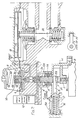
- Stepping motor drive unit B (Fig. 1) drives a threaded shaft 2A on which is threaded a nut 2 in a stepping motor electro-pneumatic (EP) unit C shown in detail in Fig. 2.
- the nut 2 cannot rotate and, therefore, moves axially when the shaft 2A rotates.
- the threaded shaft 2A may be formed integrally with the output shaft of the stepping motor.
- the nut 2 abuts the lower end of a valve cage 3 of a pilot valve so that the cage moves axially with the nut.
- the cage is always held against the nut by supply pressure acting downwardly on an annular area 3A on the cage 3.
- a pilot inlet valve 4 When rotation of the motor B causes the nut 2 and cage 3 to move upwards, a pilot inlet valve 4 is opened to connect supply air to a control chamber 5 of a relay valve and also to a chamber 6 below the pilot valve diaphragm, via a registration choke 7. Pressure builds up on the pilot valve diaphragm until it overcomes the downward force of a control spring 8 whereupon the diaphragm and an exhaust valve 9 move up, permitting the inlet valve 4 to close.
- the pressure built up in the control chamber of the- relay is proportional to the movement of the valve cage and hence the degree of rotation of the stepping motor.
- the relay valve is of conventional type of large capacity so that the effective way through should have a diameter of 3/4 inch (approx. 2 centimetres).
- the application can be increased by increasing the degree of rotation of the motor and released by reversing the rotation which causes the pilot valve cage to move down; thus permitting a spring 10 to open the exhaust valve 9 and release air from the relay valve control chamber and also the pilot valve diaphragm chamber until the pressure balances the spring load, whereupon the exhaust valve will reclose.
- a magnet valve 12 is energised to connect supply pressure to the upper side of an emergency piston 13 which moves it down against a spring 14, rendering the spring ineffective. If the magnet valve is de-energised, the chamber above the piston 13 is vented and the spring becomes effective to move up the emergency piston 13, the top end of which engages a ring 13A in a groove in the wall of the valve cage 3 thus moving valve cage 3 upwards and causing the brakes to be applied. This would occur for emergency.
- the amount the spring can move up the valve cage is determined by the position of a load cut-off stop member 15, the position of which in a taper slot 15A in the valve cage, is determined by the load dependent pressure P acting on an annulus 16A on a piston 16 against a spring 17.
- This stop prevents overbraking should there be any electrical failure.
- the stop member 15 is tapered towards its distal end and is carried by piston 16 for transverse movement relative to the slot 15A in the cage 3.
- the position of the piston 16, and hence the member 15, as determined by the load pressure signal P will limit the movement of the axially movable cage 3.
- the stepping motor rapidly moves the cage to the release position under the control of slide control circuitry (not shown).
- the feed to the relay control chamber can be choked - this choke being by-passed by a spool valve on the emergency piston 13.
- a magnet valve By incorporating a magnet valve at point X (Fig. 2) between the pilot valve output and the registration on a diaphragm 18 of a brake cylinder valve 20, it also incorporates slide control. When this occurs, the magnet valve is energised to disconnect the pilot valve output from the relay valve registration which is connected to atmosphere. Brake cylinder pressure causes the diaphragm to move up fully, causing the exhaust valve to vent the brake cylinder. If adaptive slide is required, the stepping motor, at the same time, sets the pilot valve to give the required adaptive pressure when the slide magnet is de-energised.
Landscapes
- Engineering & Computer Science (AREA)
- Transportation (AREA)
- Mechanical Engineering (AREA)
- Physics & Mathematics (AREA)
- Electromagnetism (AREA)
- Fluid Mechanics (AREA)
- Control Of Stepping Motors (AREA)
- Braking Systems And Boosters (AREA)
- Braking Arrangements (AREA)
- Electrically Driven Valve-Operating Means (AREA)
- Valve Device For Special Equipments (AREA)
- Valves And Accessory Devices For Braking Systems (AREA)
Claims (6)
Priority Applications (1)
| Application Number | Priority Date | Filing Date | Title |
|---|---|---|---|
| AT84302942T ATE32857T1 (de) | 1983-05-03 | 1984-05-02 | Bremssystem mit schrittmotor. |
Applications Claiming Priority (2)
| Application Number | Priority Date | Filing Date | Title |
|---|---|---|---|
| GB838312025A GB8312025D0 (en) | 1983-05-03 | 1983-05-03 | Brake system |
| GB8312025 | 1983-05-03 |
Publications (3)
| Publication Number | Publication Date |
|---|---|
| EP0127339A2 EP0127339A2 (de) | 1984-12-05 |
| EP0127339A3 EP0127339A3 (en) | 1985-11-06 |
| EP0127339B1 true EP0127339B1 (de) | 1988-03-09 |
Family
ID=10542060
Family Applications (1)
| Application Number | Title | Priority Date | Filing Date |
|---|---|---|---|
| EP84302942A Expired EP0127339B1 (de) | 1983-05-03 | 1984-05-02 | Bremssystem mit Schrittmotor |
Country Status (11)
| Country | Link |
|---|---|
| US (1) | US4572586A (de) |
| EP (1) | EP0127339B1 (de) |
| JP (1) | JPS59209950A (de) |
| AT (1) | ATE32857T1 (de) |
| AU (1) | AU558106B2 (de) |
| CA (1) | CA1217221A (de) |
| DE (1) | DE3469710D1 (de) |
| ES (1) | ES8503590A1 (de) |
| GB (1) | GB8312025D0 (de) |
| IN (1) | IN161273B (de) |
| ZA (1) | ZA843248B (de) |
Cited By (3)
| Publication number | Priority date | Publication date | Assignee | Title |
|---|---|---|---|---|
| US12064850B2 (en) | 2021-12-30 | 2024-08-20 | Saint-Gobain Abrasives, Inc. | Abrasive articles and methods for forming same |
| US12296434B2 (en) | 2021-12-30 | 2025-05-13 | Saint-Gobain Abrasives, Inc. | Abrasive articles and methods for forming same |
| US12473475B2 (en) | 2021-03-05 | 2025-11-18 | Saint-Gobain Abrasives, Inc. | Abrasive articles and methods for forming same |
Families Citing this family (2)
| Publication number | Priority date | Publication date | Assignee | Title |
|---|---|---|---|---|
| DE3425672C2 (de) * | 1984-07-12 | 1994-07-28 | Teves Gmbh Alfred | Bremsanlage für Kraftfahrzeuge |
| US5934765A (en) * | 1996-12-19 | 1999-08-10 | Westinghouse Air Brake Company | Electro-pneumatic brake system and controller therefor |
Family Cites Families (12)
| Publication number | Priority date | Publication date | Assignee | Title |
|---|---|---|---|---|
| US1842497A (en) * | 1928-11-03 | 1932-01-26 | Westinghouse Air Brake Co | Variable load brake |
| US2470470A (en) * | 1945-04-10 | 1949-05-17 | Parker Appliance Co | Valve operating mechanism |
| GB919519A (en) * | 1960-10-25 | 1963-02-27 | Westinghouse Brake & Signal | Improvements in or relating to electrically controlled brakes |
| CH475118A (de) * | 1967-04-25 | 1969-07-15 | Oerlikon Buehrle Ag | Bremsregeleinrichtung für druckluftgebremste Fahrzeuge, insbesondere Eisenbahnwagen |
| US3528709A (en) * | 1968-09-23 | 1970-09-15 | Gen Signal Corp | Electric current-to-pneumatic pressure transducer |
| GB1376902A (en) * | 1971-03-05 | 1974-12-11 | Westinghouse Brake & Signal | Valve assembly |
| US3814483A (en) * | 1973-05-22 | 1974-06-04 | Westinghouse Air Brake Co | Blending valve device for combining fluid pressure and dynamic brakes |
| US4021079A (en) * | 1975-12-18 | 1977-05-03 | General Signal Corporation | Blending valve for electro-pneumatic brakes |
| DE2631346A1 (de) * | 1976-07-13 | 1978-01-19 | Bosch Gmbh Robert | Blockierschutzeinrichtung fuer druckluftbetaetigte bremsen eines kraftfahrzeugs |
| US4078628A (en) * | 1976-08-16 | 1978-03-14 | The United States Of America As Represented By The Department Of Health, Education And Welfare | Double-wheel automotive hand control system |
| GB2016103B (en) * | 1978-03-08 | 1982-09-15 | Girling Ltd | Ehicle braking systems |
| US4453778A (en) * | 1980-01-10 | 1984-06-12 | Ford Motor Company | Proportioning hydraulic brake mechanism |
-
1983
- 1983-05-03 GB GB838312025A patent/GB8312025D0/en active Pending
-
1984
- 1984-04-27 IN IN360/DEL/84A patent/IN161273B/en unknown
- 1984-05-01 ZA ZA843248A patent/ZA843248B/xx unknown
- 1984-05-01 AU AU27552/84A patent/AU558106B2/en not_active Ceased
- 1984-05-02 DE DE8484302942T patent/DE3469710D1/de not_active Expired
- 1984-05-02 EP EP84302942A patent/EP0127339B1/de not_active Expired
- 1984-05-02 US US06/606,264 patent/US4572586A/en not_active Expired - Fee Related
- 1984-05-02 CA CA000453349A patent/CA1217221A/en not_active Expired
- 1984-05-02 JP JP59087994A patent/JPS59209950A/ja active Pending
- 1984-05-02 AT AT84302942T patent/ATE32857T1/de not_active IP Right Cessation
- 1984-05-03 ES ES532144A patent/ES8503590A1/es not_active Expired
Cited By (3)
| Publication number | Priority date | Publication date | Assignee | Title |
|---|---|---|---|---|
| US12473475B2 (en) | 2021-03-05 | 2025-11-18 | Saint-Gobain Abrasives, Inc. | Abrasive articles and methods for forming same |
| US12064850B2 (en) | 2021-12-30 | 2024-08-20 | Saint-Gobain Abrasives, Inc. | Abrasive articles and methods for forming same |
| US12296434B2 (en) | 2021-12-30 | 2025-05-13 | Saint-Gobain Abrasives, Inc. | Abrasive articles and methods for forming same |
Also Published As
| Publication number | Publication date |
|---|---|
| JPS59209950A (ja) | 1984-11-28 |
| IN161273B (de) | 1987-11-07 |
| ES532144A0 (es) | 1985-03-16 |
| GB8312025D0 (en) | 1983-06-08 |
| AU558106B2 (en) | 1987-01-15 |
| EP0127339A2 (de) | 1984-12-05 |
| EP0127339A3 (en) | 1985-11-06 |
| DE3469710D1 (en) | 1988-04-14 |
| ES8503590A1 (es) | 1985-03-16 |
| US4572586A (en) | 1986-02-25 |
| CA1217221A (en) | 1987-01-27 |
| ZA843248B (en) | 1984-12-24 |
| ATE32857T1 (de) | 1988-03-15 |
| AU2755284A (en) | 1984-11-08 |
Similar Documents
| Publication | Publication Date | Title |
|---|---|---|
| US3944287A (en) | Electro-pneumatic brake apparatus for railway vehicles | |
| US3799623A (en) | Controlling railway vehicle brakes | |
| US4974703A (en) | Elevator control apparatus | |
| US4418963A (en) | Control system for a vehicular braking system incorporating a hydrodynamic brake and a friction brake | |
| EP0127339B1 (de) | Bremssystem mit Schrittmotor | |
| US3398994A (en) | Anti-skid wheel control system for railway cars | |
| US5147114A (en) | Electrically controllable pressure medium brake for vehicles | |
| US3942843A (en) | Method of braking a vehicle having an antiskid brake circuit, and a modulator for such a circuit | |
| US4494199A (en) | Brake system, especially for a motor vehicle | |
| CA2212155A1 (en) | Electro-pneumatic brake system and controller therefor | |
| GB1323609A (en) | Controlling dynamic and fluid pressure brakes | |
| GB1506005A (en) | Brake system for a light rail vehicle | |
| GB2139302A (en) | Brake system incorporating a stepping motor | |
| US4021079A (en) | Blending valve for electro-pneumatic brakes | |
| EP0317183B1 (de) | Modulationsvorrichtung | |
| US4909577A (en) | Wheel skid correction device for vehicle braking system | |
| US3165180A (en) | Combination vehicle wheel spin and wheel slide control apparatus | |
| US3890013A (en) | Electrically controlled fluid pressure system for converting digital control signals to analog signals | |
| US2656222A (en) | Combined pneumatic and dynamic brake apparatus | |
| US4124980A (en) | Multi-engine control system providing equalized torque for driving a common load | |
| US3734571A (en) | Electro-pneumatic brake system | |
| US2208737A (en) | Brake control means | |
| SU643412A1 (ru) | Устройство дл управлени приводом шахтных подъемных машин | |
| SU1652267A1 (ru) | Устройство дл управлени тормозом шахтной подъемной машины | |
| US3388763A (en) | Automotive cruise control |
Legal Events
| Date | Code | Title | Description |
|---|---|---|---|
| PUAI | Public reference made under article 153(3) epc to a published international application that has entered the european phase |
Free format text: ORIGINAL CODE: 0009012 |
|
| AK | Designated contracting states |
Designated state(s): AT CH DE FR IT LI NL SE |
|
| PUAL | Search report despatched |
Free format text: ORIGINAL CODE: 0009013 |
|
| AK | Designated contracting states |
Designated state(s): AT CH DE FR IT LI NL SE |
|
| 17P | Request for examination filed |
Effective date: 19860424 |
|
| 17Q | First examination report despatched |
Effective date: 19861205 |
|
| GRAA | (expected) grant |
Free format text: ORIGINAL CODE: 0009210 |
|
| AK | Designated contracting states |
Kind code of ref document: B1 Designated state(s): AT CH DE FR IT LI NL SE |
|
| PG25 | Lapsed in a contracting state [announced via postgrant information from national office to epo] |
Ref country code: AT Effective date: 19880309 |
|
| REF | Corresponds to: |
Ref document number: 32857 Country of ref document: AT Date of ref document: 19880315 Kind code of ref document: T |
|
| ITF | It: translation for a ep patent filed | ||
| REF | Corresponds to: |
Ref document number: 3469710 Country of ref document: DE Date of ref document: 19880414 |
|
| ET | Fr: translation filed | ||
| PLBE | No opposition filed within time limit |
Free format text: ORIGINAL CODE: 0009261 |
|
| STAA | Information on the status of an ep patent application or granted ep patent |
Free format text: STATUS: NO OPPOSITION FILED WITHIN TIME LIMIT |
|
| 26N | No opposition filed | ||
| PG25 | Lapsed in a contracting state [announced via postgrant information from national office to epo] |
Ref country code: SE Effective date: 19890503 |
|
| PG25 | Lapsed in a contracting state [announced via postgrant information from national office to epo] |
Ref country code: LI Effective date: 19890531 Ref country code: CH Effective date: 19890531 |
|
| PG25 | Lapsed in a contracting state [announced via postgrant information from national office to epo] |
Ref country code: NL Effective date: 19891201 |
|
| NLV4 | Nl: lapsed or anulled due to non-payment of the annual fee | ||
| PG25 | Lapsed in a contracting state [announced via postgrant information from national office to epo] |
Ref country code: FR Free format text: LAPSE BECAUSE OF NON-PAYMENT OF DUE FEES Effective date: 19900131 |
|
| REG | Reference to a national code |
Ref country code: CH Ref legal event code: PL |
|
| PG25 | Lapsed in a contracting state [announced via postgrant information from national office to epo] |
Ref country code: DE Effective date: 19900201 |
|
| REG | Reference to a national code |
Ref country code: FR Ref legal event code: ST |
|
| EUG | Se: european patent has lapsed |
Ref document number: 84302942.2 Effective date: 19900412 |