EP0127260A2 - Gegenübergestellte Blasköpfe für die Abschreckstation eines Glasscheibentempersystems - Google Patents
Gegenübergestellte Blasköpfe für die Abschreckstation eines Glasscheibentempersystems Download PDFInfo
- Publication number
- EP0127260A2 EP0127260A2 EP84301241A EP84301241A EP0127260A2 EP 0127260 A2 EP0127260 A2 EP 0127260A2 EP 84301241 A EP84301241 A EP 84301241A EP 84301241 A EP84301241 A EP 84301241A EP 0127260 A2 EP0127260 A2 EP 0127260A2
- Authority
- EP
- European Patent Office
- Prior art keywords
- passages
- inserts
- blasthead
- glass sheet
- quenching gas
- Prior art date
- Legal status (The legal status is an assumption and is not a legal conclusion. Google has not performed a legal analysis and makes no representation as to the accuracy of the status listed.)
- Granted
Links
- 239000011521 glass Substances 0.000 title claims abstract description 87
- 238000010791 quenching Methods 0.000 title claims abstract description 77
- 238000005496 tempering Methods 0.000 title claims abstract description 38
- 230000000171 quenching effect Effects 0.000 claims abstract description 53
- 239000002131 composite material Substances 0.000 claims abstract description 22
- 238000010276 construction Methods 0.000 claims description 18
- 229910000831 Steel Inorganic materials 0.000 claims description 14
- 239000010959 steel Substances 0.000 claims description 14
- 229910052751 metal Inorganic materials 0.000 claims description 13
- 239000002184 metal Substances 0.000 claims description 13
- 239000007789 gas Substances 0.000 abstract description 37
- 239000000112 cooling gas Substances 0.000 abstract description 3
- 229910052782 aluminium Inorganic materials 0.000 description 11
- XAGFODPZIPBFFR-UHFFFAOYSA-N aluminium Chemical compound [Al] XAGFODPZIPBFFR-UHFFFAOYSA-N 0.000 description 11
- 238000005452 bending Methods 0.000 description 6
- 238000001816 cooling Methods 0.000 description 5
- 238000003466 welding Methods 0.000 description 3
- 239000000853 adhesive Substances 0.000 description 2
- 230000001070 adhesive effect Effects 0.000 description 2
- 239000005357 flat glass Substances 0.000 description 2
- 238000009827 uniform distribution Methods 0.000 description 2
- 239000005347 annealed glass Substances 0.000 description 1
- 230000000712 assembly Effects 0.000 description 1
- 238000000429 assembly Methods 0.000 description 1
- 230000000295 complement effect Effects 0.000 description 1
- 239000012809 cooling fluid Substances 0.000 description 1
- 238000009826 distribution Methods 0.000 description 1
- 238000005553 drilling Methods 0.000 description 1
- 230000000694 effects Effects 0.000 description 1
- 238000010438 heat treatment Methods 0.000 description 1
- 238000004519 manufacturing process Methods 0.000 description 1
- 239000000463 material Substances 0.000 description 1
- 125000006850 spacer group Chemical class 0.000 description 1
Images

Classifications
-
- C—CHEMISTRY; METALLURGY
- C03—GLASS; MINERAL OR SLAG WOOL
- C03B—MANUFACTURE, SHAPING, OR SUPPLEMENTARY PROCESSES
- C03B27/00—Tempering or quenching glass products
- C03B27/04—Tempering or quenching glass products using gas
-
- C—CHEMISTRY; METALLURGY
- C03—GLASS; MINERAL OR SLAG WOOL
- C03B—MANUFACTURE, SHAPING, OR SUPPLEMENTARY PROCESSES
- C03B27/00—Tempering or quenching glass products
- C03B27/04—Tempering or quenching glass products using gas
- C03B27/0404—Nozzles, blow heads, blowing units or their arrangements, specially adapted for flat or bent glass sheets
-
- C—CHEMISTRY; METALLURGY
- C03—GLASS; MINERAL OR SLAG WOOL
- C03B—MANUFACTURE, SHAPING, OR SUPPLEMENTARY PROCESSES
- C03B27/00—Tempering or quenching glass products
- C03B27/04—Tempering or quenching glass products using gas
- C03B27/044—Tempering or quenching glass products using gas for flat or bent glass sheets being in a horizontal position
- C03B27/0442—Tempering or quenching glass products using gas for flat or bent glass sheets being in a horizontal position for bent glass sheets
- C03B27/0445—Tempering or quenching glass products using gas for flat or bent glass sheets being in a horizontal position for bent glass sheets the quench unit being adapted to the bend of the sheet
Definitions
- This invention relates to a composite blasthead for a quench station of a glass sheet tempering system.
- Glass sheets are tempered to provide increased mechanical strength and the characteristics of breaking into small pieces without forming sharp slivers as is the case with annealed glass.
- tempering of glass is performed by heating and subsequent sudden chilling performed at a quench station between- opposed blastheads.
- Quenching gas which is conventionally air, is supplied to the opposed blastheads to perform the sudden chilling that tempers the glass. Best results are obtained when the quenching gas is supplied in a perpendicular relationship to the glass sheet since a more uniform distribution of the gas and the consequent cooling is achieved.
- United States Patent 4,300,937 discloses a glass tempering blasthead which includes, in a first embodiment, jet assemblies which are made by welding complementary stampings together and filling in the open ends with matching plates. In a second embodiment, each jet assembly is fabricated by welding a series of spacer elements between opposite side members to thereby produce a series of tubes.
- United States Patent 3,936,291 discloses a glass tempering blasthead that is fabricated from stamped metal components of a generally U-shaped cross section. Each of the stamped metal components includes legs that are formed to define nozzle passages when placed adjacent another like component. With such a blasthead, a single stamping die set can be utilized to stamp the required components. This blasthead has particular utility when utilized to temper flat glass as each of the nozzle passages discharges the cooling gas in an orientation perpendicular to the plane of the heated glass sheet to be tempered.
- United States Patent 3,393,062 discloses glass sheet tempering apparatus which, in one embodiment, includes individual tubes that are disposed along curved manifolds extending therefrom so as to be oriented generally perpendicular to a curved or bent glass sheet to be tempered. Such orientation provides better quenching gas distribution during cooling of a bent glass sheet and thereby provides a better product than would be the case with parallel tubes or passages.
- fabrication of this type of apparatus would be relatively expensive since the manifolds and tubes would have to be individually designed and fabricated for each particular bent shape to be tempered.
- the passages through which the cooling gas flows be constructed so as to reduce the amount of energy required to provide the cooling air while at the same time minimize back pressure effects particularly for thin glass.
- An object of the present invention is to provide an improved composite blasthead for a quench station of a glass sheet tempering system.
- a further object is to provide an improved composite blasthead for a quench station of a glass sheet tempering system wherein the blasthead cools the glass sheet material over its entire surface.
- a further object is to provide an improved composite blasthead for a quench station of a glass sheet tempering system wherein the blasthead can be fabricated from inner and outer layers of sheet metal, the inner layer being machined so that a high pressure cooling fluid can be directed onto the glass sheet at substantially uniform pressures over the entire surface of the glass sheet.
- Another object of the present invention is to provide an improved composite blasthead for a quench station of a glass sheet bending and tempering system.
- a quench station for tempering glass sheets in accordance with the present invention includes opposed blastheads of a composite construction for supplying quenching gas to a heated glass sheet of a predetermined shape positioned therebetween such that the glass sheet is rapidly cooled to provide tempering thereof.
- Each blasthead includes a pair of outer metal layers and also includes an inner machinable metal layer attached to each of the outer layers.
- the inner layer defines a plurality of passages which extend generally perpendicular to the shape of the glass sheet and which have a generally circular cross section through which the quenching gas is supplied.
- the inner layer has inner end portions that cooperate to define inlets to the adjacent passages.
- the inner layer also has outer end portions that cooperate to define outlets through which the quenching gas exits.
- the inner layer of each blasthead is aligned with the inner layer of the other blasthead.
- the inner layers are sized and spaces such that the passages of the blastheads are aligned with each other such that the quenching gas impinges on the glass sheet at uniformly spaced locations.
- each of the passages is circular in cross section along substantially the entire length of the passage.
- the inner layer comprises a plurality of inserts and at least some of the inserts of one of the blastheads have diverging sides extending from the inner ends thereof to the outer ends thereof and at least some of the inserts of the other blasthead have converging sides extending from the inner ends thereof to their outer ends.
- the converging and diverging sided inserts are positioned such that the passages extend generally perpendicular to the predetermined bent shape of a bent glass sheet during the tempering in order to supply the quenching gas in a direction perpendicular to the glass sheet.
- Each diverging sided insert on the one blasthead is aligned with a converging sided insert on the other blasthead.
- the diverging and converging sided inserts define the same included angle as each other and are sized and spaced such that the passages of each blasthead are aligned with the passages of the other blasthead, which together define an impingement pattern on the glass.
- each blasthead also includes inserts having parallel sides extending between the inner and outer ends thereof such that the passages extend generally perpendicular to the bent shape of the glass sheet adjacent any generally straight portion along its shape.
- Vehicle rear windows conventionally include a generally straight portion with opposite bent ends.
- Such a bent glass sheet shape can be conveniently tempered by opposed blastheads including the converging, diverging, and parallel sided inserts in accordance with the invention.
- each insert preferably includes an edge groove of a generally semicircular cross section extending between the inner and outer ends thereof on each side of the insert.
- Both the diverging and parallel sided inserts each have a curved inner end defining a pointed shape, while the converging sided insert has a curved inner end defining a rounded shape.
- the inner layer comprises a single insert member which has been machined to provide the necessary cooling passages.
- the inner layer comprises a pair of complimentary insert members which have been machined so when placed together provide the necessary cooling passages.
- the pair of outer layers of each blasthead comprise steel sheets and the inner layers of each blasthead comprise at least one aluminum plate or steel bar.
- This construction provides the requisite strength by virtue of the outer sheet layers as well as ease in machinability by virtue of the aluminum plate or steel bar.
- a glass sheet bending and tempering system generally indicated by reference numeral 10 includes a furnace 12 in which glass sheets are heated to a sufficiently high temperature for bending and subsequent tempering. Adjacent one of its ends, furnace 12 includes a bending station 14 at which the heated glass sheets are bent. Adjacent the bending station 14, the system 10 includes a quench station 16 for tempering bent glass sheets. Quench station 16 includes sets of opposed upper and lower blastheads 18 and 20 that have a composite construction in accordance with this invention. Quenching gas is fed through the blastheads 18 and 20 and will conventionally be air supplied thereto by suitable blowers.
- a bent glass sheet is moved on a schematically indicated mold 22 by a shuttle 24 under the operation of a suitable actuator 26 in order to position a bent glass sheet between the opposed blastheads 18 and 20 for tempering.
- the mold 22 is of the open center ring type whose periphery corresponds to the periphery of a bent glass sheet to be tempered such that quenching gas can be supplied to the bent glass sheet over substantially its entire area of both surfaces.
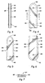
- each of the opposed blastheads 18 and 20 includes a pair of outer layers 28 and also includes an inner layer comprising a plurality of inserts 30, 32 and 34 positioned between the outer layers 28. These inserts 30, 32, and 34 cooperate-with each other as shown in FIGURE 2 to define passages 36 through which the quenching gas is supplied.
- Each insert 30, 32, and 34 has a curved inner end portion 38, 40 and 42, respectively, that cooperates with the inserts on each side thereof to define converging inlets 44 to the adjacent passages 36.
- Each insert 30, 32 and 34 also includes outer end portions 46, 48, and 50, respectively, that cooperate with the inserts on each side thereof to define outlets 52 through which the quenching gas exits the blasthead passages 36.
- At least some of the inserts 30 of the one blasthead 18 have diverging sides 54 (FIGURE 5) extending from their inner end portion 38 to their outer end portion 46. At least some of the inserts 32 of the outer blasthead 20 have converging sides 56 (FIGURE 6) extending from their inner end portions 40 to their outer end portions 48.
- the inserts 30 and 32 are positioned such that the passages 36 defined thereby extend generally perpendicular to the predetermined bent shape of the glass sheet adjacent these inserts. Quenching gas is thus supplied to the glass sheet G in a perpendicular relationship adjacent its bent areas in order to provide effective tempering.
- each diverging sided insert 30 on the one blasthead 18 is aligned with a converging sided insert 32 on the other blasthead 20.
- These diverging and converging sided inserts 30 and 32 define the same included angle as each other and are sized and spaced with respect to each other such that the passages 36 defined thereby are aligned with each other. As such, each flow of quenching gas is opposed by another aligned flow so as to optimize glass quenching.
- each of the blastheads 18 and 20 also includes a plurality of the inserts 34 which have parallel -sides 58 (FIGURE 4) extending between their inner and outer end portions 42 and 50.
- the inserts 34 are positioned adjacent the generally straight portion of the glass sheet between its opposite bent ends such that the passages 36 defined thereby extend generally perpendicular to the adjacent straight portion of the glass sheet.
- Each insert 34 on the one blasthead 18 is aligned with another insert 34 on the other blasthead 20 such that the passages 36 defined thereby are aligned with each other. As such, the flows of quenching gas from these passages oppose each other to maximize the degree of tempering.
- each of the inserts 30, 32, and 34 preferably includes an edge groove 60 of a generally semicircular cross section extending between the associated inner and outer ends thereof on each side of the insert.
- Inserts 30 and 34 which are respectively shown in FIGURES 5 and 4, and which respectively have diverging and parallel sides, have curved inner end portions 38 and 42 of a pointed shape; while the inserts 32 having the converging sides have a curved inner end portion 40 of a rounded shape.
- Both the diverging sided insert 30 shown in FIGURE 5 and the converging sided insert 32 shown in FIGURE 6 preferably define an included angle of about 3° so as to provide flexibility in accommodating different shaped bent glass sheets to be tempered. Also, all of the inserts 30, 32, and 34 are sized and spaced such that the passages 36 are not only aligned with each other but also impinge with the glass sheet at uniformly spaced locations over both its bent and generally straight areas.
- the inner end portion 46 of the insert 30 is smaller than the inner end portion 48 of the insert 32 such that the two passages 36 defined by each of these inserts are aligned with the two passages 36 defined by the other insert, and the inner end portion - 50 of the insert 34 has a size that is equal to the average size of the smaller insert end portion 46 and the larger insert end portion 48.
- projections of the passages 36 intersect the bent glass sheet at uniform intervals so as to provide the uniform distribution of quenching gas. Best results are achieved when the spaced locations of the quenching gas impingement with the glass sheet are on centers spaced about 11 ⁇ 4 inches (i.e. about 3.2 cm) from each other.
- converging inlets 44 defined by the curved inner end portions 38, 40 and 42 of the inserts 30, 32, and 34 provide efficient gas flow through the passages 36 and thereby reduce the power input to the quench unit in order to promote energy efficiency.
- the pair of outer layers 28 of each blasthead preferably comprise steel sheets to provide adequate strength at the elevated temperature involved when the blastheads are exposed to the heated glass sheets.
- the inserts 30, 32, and 34 as best seen in FIGURES 4 through 6 preferably comprise aluminum plates which can be conveniently machined from aluminum plates. Aluminum inserts 30, 32, and 34 can also be cast and then machined if necessary.
- each blasthead also includes fasteners preferably embodied by pairs of rivets 62 that secure the aluminum inserts to the outer sheet steel layers 28.
- each of the inserts 30, 32, and 34 includes a pair of holes 64 and 66 respectively adjacent their inner and outer ends.
- the rivets 62 extend through the holes 64 and 66 and through aligned holes in the outer sheet steel layers 28 to secure the inner and outer ends of each aluminum insert between the outer layers.
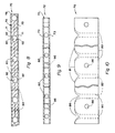
- FIGURE 8 of the drawings there is shown a portion of a second embodiment of a blasthead 70 that has a composite construction in accordance with this invention.
- quenching gas is fed - through the blasthead 70.
- the blasthead 70 includes a pair of outer layers 71 and also includes an inner layer or insert 74 positioned between the outer layers 71.
- the insert 74 comprises a pair of insert members 78 which cooperate with each other as shown in FIGURE 8 to define passages 80 through which the quenching gas is supplied.
- FIGURES 9 and 10 there is shown a portion of a third embodiment of a blasthead 72 that again has a composite construction in accordance with this invention. Again, quenching gas is fed through the blasthead 72.
- the blasthead 72 includes a pair of outer layers 73, a single insert 76, positioned between the outer layers 73.
- the insert 76 is machined as indicated in FIGURES 9 and 10 so that passages 82 are formed through which the quenching gas is supplied.
- each insert 74 and 76 has curved inner end portions 81 which cooperate to define converging inlets 86 to the adjacent passages 80 and 82 (the curved inner end portions for the second embodiment is not shown for the sake of simplicity).
- Each insert 74 and 76 also includes outer end portions 88 which cooperate to define outlets 90 through which the quenching gas exits the blasthead passages 80 and 82.
- Each of the passages 80 and each of the passages 82 are machined so as to be parallel with each other to thereby extend generally perpendicular to the adjacent straight edge portion of a glass sheet.
- Each insert 74 and 76 on the one blasthead 70 and 72 is aligned with another insert on its complimentary blasthead (not shown) such that the passages 80 and 82 are aligned with each other so that the flow of the quenching gas from these passages 80 and 82 oppose each other to maximize the degree of glass tempering.
- each of the insert members 78 include a groove 92 of a generally semicircular cross section extending between the associated inner and outer edge portions thereof.
- the converging inlets 86 defined by the curved end portions 81 of the inserts 76 and 78 and their circular cross section provide efficient gas flow through the passages 80 and 82 to thereby reduce the power input to the quench unit in-order to promote energy efficiency.
- the pair of outer layers 71 and 73 of each blasthead preferably comprise steel sheets to provide adequate strength at the elevated temperature involved when the blastheads are exposed to the heated glass sheets.
- the inserts or inner layers 74 and 76 preferably comprise aluminum sheets which can be conveniently machined. The aluminum inserts 74 and 76 can also be cast and then machined if necessary.
- Each blasthead 70 and 72 can also include fasteners embodied by rivets (not shown) to secure the aluminum inserts 74 and 76 to the outer sheet steel layers 71 and 73.
- fasteners embodied by rivets (not shown) to secure the aluminum inserts 74 and 76 to the outer sheet steel layers 71 and 73.
- the inserts 74 and 76 could be secured to the outer layers 71 and 73 by other means such as by welding or by an adhesive.
- each of the inserts 74 and 76 includes holes 94 and 96, respectively.
- the rivets extend through the holes 94 and 96 and through aligned holes in the outer sheet steel layers 71 and 73 to secure the aluminum inserts 74 and 76 between the outer layers 71 and 73.
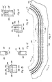
- the quench station includes sets of opposed upper and lower blastheads 118 and 120 of a fourth embodiment of the present invention which has a composite construction in accordance with this invention.
- the quenching gas which is preferably air, is fed through the blastheads 118 and 120 by several blowers.
- each of the opposed blastheads 118 and 120 includes a pair of outer layers 128 and also includes an inner layer comprising an insert or bar 130 positioned between the outer layers 128. These bars 130 cooperate with each other as shown in FIGURE 12 to define passages 136 through which the quenching gas is supplied.
- Each insert 130 has a plurality of inner end portions 138 that cooperate with each other to define inlets 144 to the adjacent passages 136.
- Each insert 130 also includes a plurality of outer end portions 146 that cooperate with each other to define outlets 152 in which the quenching gas exits the blasthead passages 136 (center line of the passages 136 being indicated by dashed lines at 154 in FIGURE 11).
- the passages 136 are drilled or punched through the bars 130 such that the passages 136 extend generally perpendicular to the predetermined bent glass of the glass sheet adjacent the passages 136. Quenching gas is thus supplied to the glass sheet G in a perpendicular relationship adjacent its bent areas in order to provide effective tempering. Furthermore, the quenching gas impinges on the glass surfaces in a uniform pattern.
- the circular cross section of the passages 136 which extend along the entire length of the passages 136 reduces the power input to the quench unit in order to promote energy efficiency as in the other embodiments.
- the bars 130 preferably comprise steel which can be conveniently machined from a steel bar.
- Each bar is preferably welded to the outer steel sheets 128 along spaced intervals.
- the steel bar 130 can also be secured to the outer layers 128 by an adhesive or other means.
- FIGURE 14 illustrates a different attachment location for the inner layer to the outer layers wherein like components to the components of FIGURE 13 are primed.
- the attachment location of FIGURE 14 is especially desirable when the width of the inner layer is relatively small. Otherwise, the components of FIGURES 13 and 14 are substantially the same and operate in substantially the same way to get substantially the same improved quenching or tempering result.
Landscapes
- Chemical & Material Sciences (AREA)
- Physics & Mathematics (AREA)
- Thermal Sciences (AREA)
- Engineering & Computer Science (AREA)
- Materials Engineering (AREA)
- Organic Chemistry (AREA)
- Re-Forming, After-Treatment, Cutting And Transporting Of Glass Products (AREA)
- Paper (AREA)
- Surgical Instruments (AREA)
- Supporting Of Heads In Record-Carrier Devices (AREA)
- Glass Compositions (AREA)
- Magnetic Heads (AREA)
- Pharmaceuticals Containing Other Organic And Inorganic Compounds (AREA)
- Nitrogen Condensed Heterocyclic Rings (AREA)
- Particle Formation And Scattering Control In Inkjet Printers (AREA)
Priority Applications (1)
| Application Number | Priority Date | Filing Date | Title |
|---|---|---|---|
| AT84301241T ATE40344T1 (de) | 1983-02-28 | 1984-02-27 | Gegenuebergestellte blaskoepfe fuer die abschreckstation eines glasscheibentempersystems. |
Applications Claiming Priority (2)
| Application Number | Priority Date | Filing Date | Title |
|---|---|---|---|
| US06/470,153 US4470838A (en) | 1983-02-28 | 1983-02-28 | Composite blasthead for quench station of glass sheet tempering system |
| US470153 | 1983-02-28 |
Publications (3)
| Publication Number | Publication Date |
|---|---|
| EP0127260A2 true EP0127260A2 (de) | 1984-12-05 |
| EP0127260A3 EP0127260A3 (en) | 1985-07-10 |
| EP0127260B1 EP0127260B1 (de) | 1989-01-25 |
Family
ID=23866488
Family Applications (1)
| Application Number | Title | Priority Date | Filing Date |
|---|---|---|---|
| EP84301241A Expired EP0127260B1 (de) | 1983-02-28 | 1984-02-27 | Gegenübergestellte Blasköpfe für die Abschreckstation eines Glasscheibentempersystems |
Country Status (16)
| Country | Link |
|---|---|
| US (1) | US4470838A (de) |
| EP (1) | EP0127260B1 (de) |
| JP (1) | JPS59169945A (de) |
| KR (1) | KR910000715B1 (de) |
| AT (1) | ATE40344T1 (de) |
| AU (1) | AU569276B2 (de) |
| BR (1) | BR8400813A (de) |
| CA (1) | CA1206005A (de) |
| DE (1) | DE3476377D1 (de) |
| EG (1) | EG16568A (de) |
| ES (1) | ES8503316A1 (de) |
| FI (1) | FI76064C (de) |
| IE (1) | IE55806B1 (de) |
| MX (1) | MX160210A (de) |
| NZ (1) | NZ206956A (de) |
| ZA (1) | ZA84767B (de) |
Families Citing this family (28)
| Publication number | Priority date | Publication date | Assignee | Title |
|---|---|---|---|---|
| US4711655A (en) * | 1986-06-09 | 1987-12-08 | Ppg Industries, Inc. | Adjustable quench for tempering a glass sheet |
| FR2768721B1 (fr) * | 1997-09-19 | 1999-10-29 | Seva | Dispositif de refroidissement de volumes en verre |
| US5925162A (en) * | 1997-11-20 | 1999-07-20 | Glasstech, Inc. | Mold support assembly for heated glass sheet mold |
| US6729160B1 (en) * | 1997-11-20 | 2004-05-04 | Glasstech, Inc. | Apparatus and method for forming heated glass sheets |
| US5917107A (en) * | 1997-11-20 | 1999-06-29 | Glasstech, Inc. | Quench loader for installing glass sheet quench module set |
| US5900034A (en) * | 1997-11-20 | 1999-05-04 | Glasstech, Inc. | Support and actuating mechanism for mold support assembly used for heated glass sheet forming |
| US5906668A (en) * | 1997-11-20 | 1999-05-25 | Glasstech, Inc. | Mold assembly for forming heated glass sheets |
| DE69824969T2 (de) * | 1997-11-20 | 2005-08-04 | Glasstech, Inc., Perrysburg | Formträgeranordnung für formen zum formen von erhizten glasscheiben |
| US6032491A (en) | 1997-11-20 | 2000-03-07 | Glasstech, Inc. | Apparatus for mold changing in heated glass sheet forming station |
| WO2000023387A1 (en) * | 1998-10-21 | 2000-04-27 | Glasstech, Inc. | Uniform distribution quenching of formed glass sheets |
| US6513348B2 (en) * | 2001-06-19 | 2003-02-04 | Glasstech, Inc. | Quench station and method for quenching formed glass sheets |
| US7958750B2 (en) * | 2005-10-21 | 2011-06-14 | Glasstech, Inc. | Glass sheet forming system |
| US8074473B2 (en) * | 2006-12-01 | 2011-12-13 | Glasstech, Inc. | Method for quenching formed glass sheets |
| US7716949B2 (en) | 2007-04-04 | 2010-05-18 | Glasstech, Inc. | Method for positioning glass sheets for forming |
| US9802853B2 (en) | 2014-07-31 | 2017-10-31 | Corning Incorporated | Fictive temperature in damage-resistant glass having improved mechanical characteristics |
| US10611664B2 (en) | 2014-07-31 | 2020-04-07 | Corning Incorporated | Thermally strengthened architectural glass and related systems and methods |
| US11097974B2 (en) | 2014-07-31 | 2021-08-24 | Corning Incorporated | Thermally strengthened consumer electronic glass and related systems and methods |
| US9611166B2 (en) | 2014-10-02 | 2017-04-04 | Glasstech, Inc. | Glass quench apparatus |
| US12338159B2 (en) | 2015-07-30 | 2025-06-24 | Corning Incorporated | Thermally strengthened consumer electronic glass and related systems and methods |
| US9758421B2 (en) | 2015-11-02 | 2017-09-12 | Glasstech, Inc. | Glass sheet processing system having cooling of conveyor roller ends |
| CN108349774B (zh) | 2015-11-02 | 2021-03-30 | 玻璃技术公司 | 玻璃片成形系统 |
| US9745147B2 (en) | 2015-11-02 | 2017-08-29 | Glasstech, Inc. | Glass sheet forming system |
| KR102492060B1 (ko) | 2016-01-12 | 2023-01-26 | 코닝 인코포레이티드 | 얇은, 열적 및 화학적으로 강화된 유리-계 제품 |
| US11795102B2 (en) | 2016-01-26 | 2023-10-24 | Corning Incorporated | Non-contact coated glass and related coating system and method |
| TW201920028A (zh) | 2017-08-24 | 2019-06-01 | 美商康寧公司 | 具有改良回火能力之玻璃 |
| TWI785156B (zh) | 2017-11-30 | 2022-12-01 | 美商康寧公司 | 具有高熱膨脹係數及對於熱回火之優先破裂行為的非離子交換玻璃 |
| WO2020219290A1 (en) | 2019-04-23 | 2020-10-29 | Corning Incorporated | Glass laminates having determined stress profiles and methods of making the same |
| CN116811379A (zh) | 2019-08-06 | 2023-09-29 | 康宁股份有限公司 | 具有用于阻止裂纹的埋入式应力尖峰的玻璃层压体及其制造方法 |
Family Cites Families (7)
| Publication number | Priority date | Publication date | Assignee | Title |
|---|---|---|---|---|
| US2921411A (en) * | 1951-07-27 | 1960-01-19 | Pittsburgh Plate Glass Co | Apparatus for the air chilling of bent glass |
| US3294519A (en) * | 1963-08-01 | 1966-12-27 | Pittsburgh Plate Glass Co | Glass sheet tempering apparatus |
| GB1107265A (en) * | 1963-10-02 | 1968-03-27 | Triplex Safety Glass Co | Improvements in or relating to apparatus for and methods of toughening glass articles |
| GB1411140A (en) * | 1972-08-14 | 1975-10-22 | Mcmaster H A | Fluid-flow nozzle assembly for glass-tempering blastheads and a blasthead including such an assembly |
| GB1494291A (en) * | 1975-02-12 | 1977-12-07 | Libbey Owens Ford Co | Bending and tempering glass sheets |
| US4300937A (en) * | 1979-05-29 | 1981-11-17 | Tgs Systems, Inc. | Quench devices, glass tempering furnaces, and methods of utilizing same |
| US4297121A (en) * | 1979-05-29 | 1981-10-27 | Tgs Systems, Inc. | Glass tempering furnaces and systems |
-
1983
- 1983-02-28 US US06/470,153 patent/US4470838A/en not_active Expired - Lifetime
-
1984
- 1984-01-27 NZ NZ206956A patent/NZ206956A/en unknown
- 1984-02-01 ZA ZA84767A patent/ZA84767B/xx unknown
- 1984-02-03 AU AU24063/84A patent/AU569276B2/en not_active Ceased
- 1984-02-22 BR BR8400813A patent/BR8400813A/pt not_active IP Right Cessation
- 1984-02-23 MX MX200432A patent/MX160210A/es unknown
- 1984-02-27 IE IE467/84A patent/IE55806B1/xx unknown
- 1984-02-27 FI FI840788A patent/FI76064C/fi not_active IP Right Cessation
- 1984-02-27 EP EP84301241A patent/EP0127260B1/de not_active Expired
- 1984-02-27 DE DE8484301241T patent/DE3476377D1/de not_active Expired
- 1984-02-27 CA CA000448335A patent/CA1206005A/en not_active Expired
- 1984-02-27 KR KR1019840000953A patent/KR910000715B1/ko not_active Expired
- 1984-02-27 ES ES530070A patent/ES8503316A1/es not_active Expired
- 1984-02-27 AT AT84301241T patent/ATE40344T1/de not_active IP Right Cessation
- 1984-02-28 JP JP59037184A patent/JPS59169945A/ja active Granted
- 1984-02-28 EG EG141/84A patent/EG16568A/xx active
Also Published As
| Publication number | Publication date |
|---|---|
| IE55806B1 (en) | 1991-01-16 |
| FI840788A0 (fi) | 1984-02-27 |
| IE840467L (en) | 1984-08-28 |
| FI840788A7 (fi) | 1984-08-29 |
| ES530070A0 (es) | 1985-02-01 |
| AU569276B2 (en) | 1988-01-28 |
| CA1206005A (en) | 1986-06-17 |
| DE3476377D1 (en) | 1989-03-02 |
| EP0127260B1 (de) | 1989-01-25 |
| KR910000715B1 (ko) | 1991-01-31 |
| KR840007546A (ko) | 1984-12-08 |
| AU2406384A (en) | 1984-09-06 |
| JPS59169945A (ja) | 1984-09-26 |
| FI76064C (fi) | 1988-09-09 |
| JPS6235976B2 (de) | 1987-08-05 |
| MX160210A (es) | 1989-12-27 |
| ZA84767B (en) | 1984-09-26 |
| ATE40344T1 (de) | 1989-02-15 |
| NZ206956A (en) | 1985-12-13 |
| EG16568A (en) | 1991-12-30 |
| BR8400813A (pt) | 1984-10-02 |
| EP0127260A3 (en) | 1985-07-10 |
| ES8503316A1 (es) | 1985-02-01 |
| US4470838A (en) | 1984-09-11 |
| FI76064B (fi) | 1988-05-31 |
Similar Documents
| Publication | Publication Date | Title |
|---|---|---|
| EP0127260B1 (de) | Gegenübergestellte Blasköpfe für die Abschreckstation eines Glasscheibentempersystems | |
| US6295842B1 (en) | Uniform distribution quenching of formed glass sheets | |
| US5078775A (en) | Glass sheet gas support | |
| NO148705B (no) | Varmevekslepanel og fremgangsmaate til fremstilling av dette | |
| US4515622A (en) | Glass sheet quench including oppositely angled jets | |
| PL187879B1 (pl) | Urządzenie do chłodzenia wypukłych tafli szklanych | |
| USH777H (en) | Method for jet gas impingement quenching | |
| US5021075A (en) | Device for tempering by contact of glazings | |
| US4323385A (en) | Nozzle arrangement for glass sheet tempering apparatus | |
| SE544654C2 (en) | A method and a system for brazing a plate heat exchanger | |
| US3981350A (en) | Apparatus for supporting and cooling a continuously cast product | |
| KR100640134B1 (ko) | 편평 제품과의 열교환용 장치 및 편평 제품용 냉각 장치 | |
| EP0521603B1 (de) | Tragevorrichtung für Glasscheibe | |
| KR930002637B1 (ko) | 템퍼링중유리판을지지하기위한프레임 | |
| WO2025196204A1 (en) | Heat exchanger core for a printed circuit heat exchanger and printed circuit heat exchanger | |
| JP2953986B2 (ja) | ガラス板の冷却装置 | |
| MXPA01003934A (en) | Uniform distribution quenching of formed glass sheets | |
| JPH09110451A (ja) | ガラス板の強化方法及び装置 |
Legal Events
| Date | Code | Title | Description |
|---|---|---|---|
| PUAI | Public reference made under article 153(3) epc to a published international application that has entered the european phase |
Free format text: ORIGINAL CODE: 0009012 |
|
| AK | Designated contracting states |
Designated state(s): AT BE CH DE FR GB IT LI LU NL SE |
|
| PUAL | Search report despatched |
Free format text: ORIGINAL CODE: 0009013 |
|
| AK | Designated contracting states |
Designated state(s): AT BE CH DE FR GB IT LI LU NL SE |
|
| 17P | Request for examination filed |
Effective date: 19851218 |
|
| 17Q | First examination report despatched |
Effective date: 19861031 |
|
| GRAA | (expected) grant |
Free format text: ORIGINAL CODE: 0009210 |
|
| AK | Designated contracting states |
Kind code of ref document: B1 Designated state(s): AT BE CH DE FR GB IT LI LU NL SE |
|
| PG25 | Lapsed in a contracting state [announced via postgrant information from national office to epo] |
Ref country code: SE Effective date: 19890125 Ref country code: NL Effective date: 19890125 Ref country code: LI Effective date: 19890125 Ref country code: CH Effective date: 19890125 Ref country code: AT Effective date: 19890125 |
|
| REF | Corresponds to: |
Ref document number: 40344 Country of ref document: AT Date of ref document: 19890215 Kind code of ref document: T |
|
| ITF | It: translation for a ep patent filed | ||
| PG25 | Lapsed in a contracting state [announced via postgrant information from national office to epo] |
Ref country code: LU Free format text: LAPSE BECAUSE OF NON-PAYMENT OF DUE FEES Effective date: 19890228 |
|
| REF | Corresponds to: |
Ref document number: 3476377 Country of ref document: DE Date of ref document: 19890302 |
|
| ET | Fr: translation filed | ||
| REG | Reference to a national code |
Ref country code: CH Ref legal event code: PL |
|
| NLV1 | Nl: lapsed or annulled due to failure to fulfill the requirements of art. 29p and 29m of the patents act | ||
| PLBE | No opposition filed within time limit |
Free format text: ORIGINAL CODE: 0009261 |
|
| STAA | Information on the status of an ep patent application or granted ep patent |
Free format text: STATUS: NO OPPOSITION FILED WITHIN TIME LIMIT |
|
| 26N | No opposition filed | ||
| PGFP | Annual fee paid to national office [announced via postgrant information from national office to epo] |
Ref country code: FR Payment date: 19910212 Year of fee payment: 8 |
|
| PGFP | Annual fee paid to national office [announced via postgrant information from national office to epo] |
Ref country code: GB Payment date: 19910215 Year of fee payment: 8 |
|
| ITTA | It: last paid annual fee | ||
| PGFP | Annual fee paid to national office [announced via postgrant information from national office to epo] |
Ref country code: DE Payment date: 19910328 Year of fee payment: 8 |
|
| PGFP | Annual fee paid to national office [announced via postgrant information from national office to epo] |
Ref country code: BE Payment date: 19910403 Year of fee payment: 8 |
|
| PG25 | Lapsed in a contracting state [announced via postgrant information from national office to epo] |
Ref country code: GB Effective date: 19920227 |
|
| PG25 | Lapsed in a contracting state [announced via postgrant information from national office to epo] |
Ref country code: BE Effective date: 19920228 |
|
| BERE | Be: lapsed |
Owner name: GLASSTECH INC. Effective date: 19920228 |
|
| GBPC | Gb: european patent ceased through non-payment of renewal fee | ||
| PG25 | Lapsed in a contracting state [announced via postgrant information from national office to epo] |
Ref country code: FR Effective date: 19921030 |
|
| PG25 | Lapsed in a contracting state [announced via postgrant information from national office to epo] |
Ref country code: DE Effective date: 19921103 |
|
| REG | Reference to a national code |
Ref country code: FR Ref legal event code: ST |