EP0127085A2 - Steuerungsvorrichtung für eine hydraulische automatische Kupplung - Google Patents
Steuerungsvorrichtung für eine hydraulische automatische Kupplung Download PDFInfo
- Publication number
- EP0127085A2 EP0127085A2 EP84105648A EP84105648A EP0127085A2 EP 0127085 A2 EP0127085 A2 EP 0127085A2 EP 84105648 A EP84105648 A EP 84105648A EP 84105648 A EP84105648 A EP 84105648A EP 0127085 A2 EP0127085 A2 EP 0127085A2
- Authority
- EP
- European Patent Office
- Prior art keywords
- engine
- vehicle
- brake
- automatic clutch
- hydraulic automatic
- Prior art date
- Legal status (The legal status is an assumption and is not a legal conclusion. Google has not performed a legal analysis and makes no representation as to the accuracy of the status listed.)
- Withdrawn
Links
- 238000000034 method Methods 0.000 claims description 10
- 239000012530 fluid Substances 0.000 claims description 7
- 230000001105 regulatory effect Effects 0.000 claims description 5
- 230000003247 decreasing effect Effects 0.000 abstract description 2
- 230000005540 biological transmission Effects 0.000 description 8
- 230000008569 process Effects 0.000 description 6
- 239000002826 coolant Substances 0.000 description 3
- 239000000446 fuel Substances 0.000 description 3
- 230000009467 reduction Effects 0.000 description 3
- 230000004044 response Effects 0.000 description 3
- RTZKZFJDLAIYFH-UHFFFAOYSA-N Diethyl ether Chemical compound CCOCC RTZKZFJDLAIYFH-UHFFFAOYSA-N 0.000 description 2
- 238000010276 construction Methods 0.000 description 2
- 230000001276 controlling effect Effects 0.000 description 2
- 230000007423 decrease Effects 0.000 description 2
- 230000006870 function Effects 0.000 description 2
- 238000005461 lubrication Methods 0.000 description 2
- 230000007246 mechanism Effects 0.000 description 2
- 230000009471 action Effects 0.000 description 1
- 230000033228 biological regulation Effects 0.000 description 1
- 230000000994 depressogenic effect Effects 0.000 description 1
- 238000010586 diagram Methods 0.000 description 1
- 238000007599 discharging Methods 0.000 description 1
- 230000000694 effects Effects 0.000 description 1
- 239000003112 inhibitor Substances 0.000 description 1
- 230000000977 initiatory effect Effects 0.000 description 1
- 238000009877 rendering Methods 0.000 description 1
Images


Classifications
-
- B—PERFORMING OPERATIONS; TRANSPORTING
- B60—VEHICLES IN GENERAL
- B60W—CONJOINT CONTROL OF VEHICLE SUB-UNITS OF DIFFERENT TYPE OR DIFFERENT FUNCTION; CONTROL SYSTEMS SPECIALLY ADAPTED FOR HYBRID VEHICLES; ROAD VEHICLE DRIVE CONTROL SYSTEMS FOR PURPOSES NOT RELATED TO THE CONTROL OF A PARTICULAR SUB-UNIT
- B60W10/00—Conjoint control of vehicle sub-units of different type or different function
- B60W10/04—Conjoint control of vehicle sub-units of different type or different function including control of propulsion units
- B60W10/06—Conjoint control of vehicle sub-units of different type or different function including control of propulsion units including control of combustion engines
-
- B—PERFORMING OPERATIONS; TRANSPORTING
- B60—VEHICLES IN GENERAL
- B60W—CONJOINT CONTROL OF VEHICLE SUB-UNITS OF DIFFERENT TYPE OR DIFFERENT FUNCTION; CONTROL SYSTEMS SPECIALLY ADAPTED FOR HYBRID VEHICLES; ROAD VEHICLE DRIVE CONTROL SYSTEMS FOR PURPOSES NOT RELATED TO THE CONTROL OF A PARTICULAR SUB-UNIT
- B60W10/00—Conjoint control of vehicle sub-units of different type or different function
- B60W10/02—Conjoint control of vehicle sub-units of different type or different function including control of driveline clutches
-
- B—PERFORMING OPERATIONS; TRANSPORTING
- B60—VEHICLES IN GENERAL
- B60W—CONJOINT CONTROL OF VEHICLE SUB-UNITS OF DIFFERENT TYPE OR DIFFERENT FUNCTION; CONTROL SYSTEMS SPECIALLY ADAPTED FOR HYBRID VEHICLES; ROAD VEHICLE DRIVE CONTROL SYSTEMS FOR PURPOSES NOT RELATED TO THE CONTROL OF A PARTICULAR SUB-UNIT
- B60W10/00—Conjoint control of vehicle sub-units of different type or different function
- B60W10/04—Conjoint control of vehicle sub-units of different type or different function including control of propulsion units
-
- B—PERFORMING OPERATIONS; TRANSPORTING
- B60—VEHICLES IN GENERAL
- B60W—CONJOINT CONTROL OF VEHICLE SUB-UNITS OF DIFFERENT TYPE OR DIFFERENT FUNCTION; CONTROL SYSTEMS SPECIALLY ADAPTED FOR HYBRID VEHICLES; ROAD VEHICLE DRIVE CONTROL SYSTEMS FOR PURPOSES NOT RELATED TO THE CONTROL OF A PARTICULAR SUB-UNIT
- B60W10/00—Conjoint control of vehicle sub-units of different type or different function
- B60W10/10—Conjoint control of vehicle sub-units of different type or different function including control of change-speed gearings
- B60W10/11—Stepped gearings
-
- B—PERFORMING OPERATIONS; TRANSPORTING
- B60—VEHICLES IN GENERAL
- B60W—CONJOINT CONTROL OF VEHICLE SUB-UNITS OF DIFFERENT TYPE OR DIFFERENT FUNCTION; CONTROL SYSTEMS SPECIALLY ADAPTED FOR HYBRID VEHICLES; ROAD VEHICLE DRIVE CONTROL SYSTEMS FOR PURPOSES NOT RELATED TO THE CONTROL OF A PARTICULAR SUB-UNIT
- B60W30/00—Purposes of road vehicle drive control systems not related to the control of a particular sub-unit, e.g. of systems using conjoint control of vehicle sub-units
- B60W30/18—Propelling the vehicle
- B60W30/1819—Propulsion control with control means using analogue circuits, relays or mechanical links
-
- B—PERFORMING OPERATIONS; TRANSPORTING
- B60—VEHICLES IN GENERAL
- B60W—CONJOINT CONTROL OF VEHICLE SUB-UNITS OF DIFFERENT TYPE OR DIFFERENT FUNCTION; CONTROL SYSTEMS SPECIALLY ADAPTED FOR HYBRID VEHICLES; ROAD VEHICLE DRIVE CONTROL SYSTEMS FOR PURPOSES NOT RELATED TO THE CONTROL OF A PARTICULAR SUB-UNIT
- B60W2540/00—Input parameters relating to occupants
- B60W2540/12—Brake pedal position
-
- B—PERFORMING OPERATIONS; TRANSPORTING
- B60—VEHICLES IN GENERAL
- B60W—CONJOINT CONTROL OF VEHICLE SUB-UNITS OF DIFFERENT TYPE OR DIFFERENT FUNCTION; CONTROL SYSTEMS SPECIALLY ADAPTED FOR HYBRID VEHICLES; ROAD VEHICLE DRIVE CONTROL SYSTEMS FOR PURPOSES NOT RELATED TO THE CONTROL OF A PARTICULAR SUB-UNIT
- B60W2710/00—Output or target parameters relating to a particular sub-units
- B60W2710/06—Combustion engines, Gas turbines
- B60W2710/0644—Engine speed
- B60W2710/065—Idle condition
Definitions
- the present invention relates to a control device for a vehicle having a hydraulic automatic clutch.
- the clutch supply oil pressure at engine idling is set at a value just prior to initiation of the clutch engagement, there takes place an event where the clutch supply oil pressure will exceed the oil pressure value at which the clutch starts engaging owing to a variation in the idle speed (the idle speed increases when a choke is used or an air conditioner is used), thereby causing the vehicle to start unintentionally.
- a pre-start state i.e., a state where the clutch is kept in a predetermined slightly engaged state, by regulating the oil pressure supplied to the clutch, under a condition where the engine is idling and the vehicle is at a standstill).
- An object of the present invention is to provide a control device which provides a better fuel economy during idle operation of the engine.
- One aspect of the present invention resides in that a hydraulic automatic clutch is completely released under a condition where a vehicle does not start immediately, although it maintains the hydraulic automatic clutch in slightly engaged state under a condition where the vehicle is about to start.
- Another aspect of the present invention resides in that in addition to completely releasing the hydraulic automatic clutch, an idle speed of the engine is adjusted to a low idle speed.
- FIG. 1 to 4 a first embodiment according to the present invention is described.
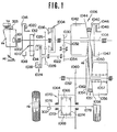
- a vehicle having an engine EN with a throttle TH which opens in degrees as an accelerator pedal AC is depressed and a continuously variable transmission.
- the vehicle has a foot operated brake FB and a parking brake PB which are diagrammatically shown.
- the continuously variable transmission provided with a forward clutch 1004 and a reverse clutch 1024, each of which is a hydraulic automatic clutch.
- This continuously variable transmission is able to transmit rotation of an input shaft 1002, via a drive pulley 1006, a V-belt 1050, a driven pulley 1051 and etc., to output shafts 1076 and 1078 when the for,7ard clutch 1004 or the reverse clutch 1024 is engaged.
- This continuously variable transmission comprises input shaft 1002, forward clutch 1004, drive pulley 1006, a drive shaft 1008, an oil pump 1010, a drive gear 1012, a driven gear 1014, a rotatable flume 1016, an oil reservoir 1018, a pitot tube 1020, an auxiliary shaft 1022, reverse clutch 1024, gears 1026, 1028, 1030, 1032 and 1034, piston chambers 1036 and 1038, a fixed conical disc 1040, a drive pulley cylinder chamber 1042, a movable conical disc 44, a rotatable flume 1046, an oil reservoir 1047, a pitot tube 1048, a V-belt 1050, a driven pulley 1051, a driven shaft 1052, a fixed conical disc 1054, a driven pulley cylinder chamber 1056, a spring 1057, a movable conical disc 1058, a gear 1060, a ring gear 1062, a differential case 1064, pinion gears
- Figs. 2A and 2B show a control system, including a control device according to the present invention, for the continuously variable transmission.
- the control system for the continuously variable transmission comprises an oil pump 1010, a line pressure regulator valve 1102, a manual valve 1104, a shift control valve 1106, a clutch complete engagement control valve 1108, a shift motor (a stepper motor) 1110, a shift operating mechanism 1112, a throttle valve 1114, a starting valve 2116, a start adjustement valve 1118, a maximum reduction ratio maintaining valve 1120, a reverse inhibitor valve 1122, a lubrication valve 1124, a tank 1130, an electronic control unit 1300 and etc., and they are interconnected as illsutrated and connected also to the piston chamber 1036 of the forward clutch 1004, the piston chamber 1038 of the reverse clutch 1024, the drive pulley cylinder chamber 1042, the driven pulley cylinder chamber 1056 and pitot tubes 1020 and 1048.
- the starting valve 2116 comprises a valve bore 2204 provided with ports 2204a, 2204b, 2204c, 2204d, 2204e and 2204f, a spool 2206 having thereon lands 2206a, 2206b, 2206c and 2206d (the land 2206a has a tapered portion on the lefthand side thereof), and a spring 2208 biasing the spool 2206 to the left, as viewed in the Fig. 2A.
- the port 2204a communicates with the oil conduit 1140 which connects via an orifice 1210 with the oil conduit 1162 forming the throttle pressure circuit.
- the port 2204b is drained through the oil conduit 1200 forming a drain circuit (this oil conduit 1200 communicating with a portion between the oil pump 1010 and the strainer 1131).
- the port 2204c is a drain port, too.
- the port 2204d is connected via the oil conduit 1212 with the start adjusting valve 1118.
- the port 2204e communicates via the oil conduit 1190 with the port 1186b of the clutch complete engagement control valve 1108 (see Fig. 2B).
- the port 2204f communicates via the oil conduit 1214 with the pitot tube 1020. That is, the signal oil pressure indicative of revolution speed of the input shaft 1002 (i.e., the engine speed signal oil pressure) is supplied to the port 2204f.
- the ports 2204d, 2204e and 2204f have at their inlets orifices 2216, 2218 and 2220, respectively.
- the starting valve 2116 has a pressure reducing function to generate an oil pressure (start pressure) within the oil conduit 1140 by discharging oil in the port 2204a toward the port 2204b depending upon the position of the spool 2206. If the spool 2206 is disposed to the left as viewed in Fig.
- the oil pressure at the port 2204a is relatively high because a clearance passage from the port 2204a to the port 2204b is narrow, while if the spool 2206 has moved to the right, the oil pressure at the port 2204a drops because the clearance passage from the port 2204a to the port 2204b becomes wide and the amount of oil drainage increases. Since the oil conduit 1162 forming the throttle pressure circuit communicates via the orifice 1210 with the oil conduit 1140 forming the start pressure circuit, the throttle pressure in the oil conduit 1162 is not substantially affected even if the oil pressure in the oil conduit 1140 drops.
- the position of the spool 2206 is determined on the balance of rightwardly directed force by oil pressure (start adjustment pressure) in the port 2204a acting on the land 2206a and by the oil pressure (start adjustment pressure) acting on the differential area between the lands 2206b and 2206c with the total of leftwardly directed force due to oil pressure (drive pulley revolution speed signal oil pressure) in the port 2204e acting on the differential area between the lands 2206c and 2206d and the leftwardly directed force due to oil pressure (engine revolution speed signal oil pressure) in the port 2204f acting on the 2206d.
- the rod of the clutch complete engagement control valve 1108 is disposed to the leftmost position and the oil conduit 1190 is drained so that the drive pulley revolution speed oil pressure signal does not act in the port 2204e of the starting valve 2116. Accordingly, the start pressure is controlled in response to the start adjustment pressure and engine speed signal oil pressure and thus gradually increases as the engine speed increases.
- This start pressure is supplied to the forward clutch 1004 (or reverse clutch 1024), rendering the clutch to engage gradually, thus permitting the vehicle to start moving smoothly.
- the clutch complete engagement control valve 1108 is rendered to switch by the action of the stepper motor 1110, delivering through the oil conduit 1190 the drive pulley revolution speed signal pressure to the port 2204e, causing the start pressure to increase rapidly. With this rapid increase in the start pressure, the forward clutch 1004 (or reverse clutch 1024) is firmly engaged and thus become free from slipping.
- the start adjusting valve 1118 comprises a force motor 1224--which regulates the rate of flow of oil discharged from the oil conduit 1212 to the port 1222 (this port 1222 communicating with the oil conduit 1200 forming the drain circuit) by a plunger 1224a.
- a force motor 1224 which regulates the rate of flow of oil discharged from the oil conduit 1212 to the port 1222 (this port 1222 communicating with the oil conduit 1200 forming the drain circuit) by a plunger 1224a.
- an oil under low pressure is supplied via an orifice 1226 from the oil conduit 1164 forming the lubrication circuit.
- the oil pressure (start adjustment pressure) in the oil conduit 1212 is controlled in response to the amount of current passing through the force motor 1224 because the force motor 1224 discharges the oil from the oil conduit 1212 inversely proportional to the amount of current passing therethrough.
- the amount of current passing through the force motor 1224 is controlled in the later described manner by the control unit 1300.
- the start pressure (the pressure resulting from the regulation in the starting valve 2116) is adjusted to a pressure state which maintains the forward clutch 1004 or reverse clutch 1024 in a predetermined slightly engaged state (under a condition where a brake is not used) or in a completely released state (under a condition where the brake is used), which will be later described.
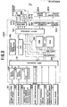
- control unit 1300 which controls the stepper motor 1110 and the force motor 1224.
- the control unit 1300 receives as inputs thereto electric signals from an engine revolution speed sensor 301, a vehicle speed sensor 302, a throttle opening degree sensor (or an intake manifold sensor) 303, a shift position switch 304, a shift reference switch 1298, an engine coolant temperature sensor 306, and a brake sensor 307.
- the engine revolution speed sensor 301 detects an engine revolution speed by measuring the number of ignition spark pluses of the engine
- the vehicle speed sensor 302 detects a vehicle speed by measuring the revolution of the output shaft of the continuously variable transmission.
- the throttle opening degree sensor (or intake mainifold vacuum sensor) 303 detects the engine throttle opening degree in terms of an electric voltage signal (in the case of the intake manifold vacuum sensor, the intake manifold vacuum is detected in terms of an electric voltage signal).
- the shift position switch 304 detects which one of range positions, namely, P, N, D, and L, the before mentioned manual valve 104 assumes.
- the shift reference switch 1298 is turned on when the sleeve 1182 of the before mentioned shift operating mechanism 1112 has come to a position corresponding to the largest reduction ratio.
- the engine coolant temperature 306 generates a signal when the engine coolant temperature is lower than a predetermined value.
- the brake sensor 307 detects the application of one of the foot operated brake FB and the parking brake PB.
- the brake sensor 307 is in the form of a circuit which is closed upon detecting the application of one of the brakes FB and PB.
- the signals generated by the engine revolution speed sensor 301 and vehicle speed sensor 302 are sent to an input interface 311 after passage through wave shapers 308 and 309, respectively, and the electric voltage from the throttle opening degree sensor (or intake manifold vacuum sensor) 303 is converted at an A/D converter 310 into a digital signal before being sent to the input interface 311.
- the control unit 1300 includes the input interface 311, a reference pulse generator 312, a CPU (Central Processor Unit) 313, a ROM (Read Only Memory) 314, a RAM (Randam Access Memory) 315, and an output interface 316, which are linked with each other by an address bus 319 and a data bus 320.
- the reference pulse generator 312 generates a reference pulse which actuates the CPU 313.
- the ROM 314 stores programs necessary for controlling the stepper motor 1110 and force motor 1224 and data necessary for controlling them.
- the RAM stores various parameters necessary for processing information from each of the sensors and switches and those necessary for control. Output signals from the shift control apparatus 300 are sent out to the stepper motor 1110 and force motor 1224 via amplifier 317 and electric current controller 318, respectively.
- control unit 1300 controls the stepper motor 1110, the description as to how the stepper motor 1110 is controlled is omitted because it is less related to the present invention. The description of that portion which has not been described is found in the before mentioned U.S. patent application Ser. No. 543,838.
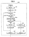
- the force motor control routine 500 has a function to place the forward clutch 1004 (or the reverse clutch 1024) in the predetermined slightly engaged state by regulating a start pressure via the start adjusting valve 1118 and the starting valve 2116 when the foot operated brake FB and the parking brake PB are both released under a condition where the engine is idling when the vehicle is at a standstill, and to completely release the clutch 1004 or 1024 when one of the brakes FB and PB is applied under this condition.
- the execution of this force motor control routine 500 is repeated after a predetermined time (i.e., the following routine 500 is repeatedly executed within a short period of time).
- a throttle opening degree TH is read in from the throttle opening degree sensor 303 (in a step 501), and a vehicle speed V is read in from the vehicle speed sensor 302 (in a step 503).
- a determination is made whether the vehicle speed V is less than the predetermined small value Vo or not. If it is less than or equal to the predetermined small value Vo, the program proceeds to a step 507 where a determination is made whether the throttle opening degree TH is less than a predetermined small value THo or not. If it is less than or equal to the predetermined small value THo (that is, when the vehicle is at a standstill and the engine idles), the program proceeds to a step 508a where the brake operation indicative signal is read in from the brake sensor 306.
- the brake sensor 306 detects the application of one of the foot operated brake FB and the parking brake PB. If both the foot brake FB and the parking brake PB are not used or released, the program proceeds to a step 509, while if used, the program proceeds to a step 510. If in the step 505 or in the step 509, V is greater than Vo or TH is greater than THo, the program proceeds to a step 527 where the same force motor electric signal I1 as that in the preceding routine is sent out, i.e., the electric current signal I1 sent out immediately before the state where V is greater than Vo or TH is greater than THo is accomplished is sent out again.
- an engine speed NE is read in from the engine revolution speed sensor 301.
- the force motor electric current signal 12 is given C3-NE. Since C3 is a constant having a large value and 12 is a relatively large value, the start adjustment pressure takes a relatively high oil pressure (this causes the start pressure to have a low oil pressure, thus completely releasing the clutch). As long as it provides the start pressure low enough to release the clutch, the force motor electric current 12 may be computed or set in any desired manner.
- the program proceeds to a step 528 where the above mentioned force motor electric signal 12 is sent out.
- the program proceeds to a step 511 where the force motor electric signal 11 is computed in the following manner.
- the force motor electric signal 11 can be expressed by C1 and C2 are constants which will be described later.
- the start pressure Ps becomes a predetermined value which is determined by the spring 208 as will be described hereinafter.
- the equilibrium state of the start valve 116 can be expressed by an equation as follows: where:
- the start pressure Ps becomes a constant determined by F and As.
- the values F and As are set such that the start pressure Ps becomes an oil pressure which places the clutch in slightly engaged
- the program proceeds to a step 527 where the electric signal 11 is sent out.
- the start pressure Ps is kept at an oil pressure which places the forward clutch 1004 (or the reverse clutch 1024) in the slightly engaged state as a result of the process along step 508a ⁇ 508b - 509 ⁇ 511 - ⁇ 527.
- the start pressure Ps takes a value resulting from adding to the above mentioned constant pressure an oil pressure which corresponds to the engine speed, thus engaging the forward clutch 1004 (or the reverse clutch 1024), thereby enabling the vehicle to move off from a standstill. This provides a stable starting operation of the vehicle without engine racing nor unintentional starting irrespective of variation in engine idle speed.
- start pressure Ps is so controlled as to always place the clutch in the slightly engaged state irrespective of idle speed due to the above mentioned effect although the idle speed of the engine deviates from a normal preset value when the choke is used or the cooler is used or the engine operates irregularly.
- step 508a 508b ⁇ 510 ⁇ 512 ⁇ 528 the clutch is completely released when the brake is applied (that is, in the case where the starting of the vehile is less likely to take place immediately). Therefore, since the traction torque by the clutch is zero and the load on the engine becomes small, it is possible to set the idle speed of the engine low.
- FIG. 1 A second embodiment is hereinafter described referring to Figs. 1, 2A, 2B, 5 and 6.
- the second embodiment is similar to the first embodiment but different from the latter in that it has an idle adjusting device 900 and an electric amplifier 322 which are shown in Fig. 3 by phantom lines. Referring to Fig. 5, the idle adjusting device 900 is described.
- a bypass passage 906 is arranged.
- the rate of fluid flow passing through the bypass passage 906 is controlled by an electromagnetic valve 908.
- the electromagnetic valve 908 adjusts the cross sectional area of the bypass passage 906 in response to an electric current signal supplied thereto by the control unit 1300 via the current amplifier 322. As the cross sectional area of the bypass passage 906 increases, the flow rate of air admitted to the engine increases, causing an increase in the idle speed, whereas as the cross sectional area decreases, the flow rate of air supplied to the engine decreases, causing a drop in the idle speed accordingly.
- a force motor and idle adjusting device control routine 500A is described.
- the forward clutch 1004 (or reverse clutch 1024) is placed in a predetermined slightly engaged state and at the same time, the idle speed is increased by the idle adjusting device 900.
- the brake is applied under the same condition, the clutch is completely released and at the same time, the idle speed is decreased by the idle adjusting device 900.
- This control routine is substantially the same as the control routine 500 shown in Fig. 4, but it is different from the latter in the provision of new steps 513, 529 disposed in a flow of process executed when a brake is released in a step 508b and new steps 514, 530 disposed in a flow of process which is executed when the brake is applied in the step 508b.
- step 508b is executed where a determination is made whether the brake, i.e., the foot operated brake or the parking brake, is ON (applied) or not (released). If the brake is released, the program proceeds to a step 509, whereas if it is applied, the program proceeds to a step 510.
- the brake i.e., the foot operated brake or the parking brake
- the program proceeds to a step 527 and then to a step 529 where in these steps the same force motor electric signal I1 and idle adjusting electric signal Q2 as those in the preceding routine are sent out, i.e., the electric current signal I1 and the idle adjusting electric signal Q2 sent out immediately before the state where V is greater than Vo or TH is greater than THc is accomplished are sent out again.
- the idle adjusting electric signal Q1 is given a value q1 in the step 514.
- the idle adjusting device 900 adjusts the engine to operate at a low idle speed.
- the program proceeds to a step 528 where the above mentioned force motor electric signal 12 is produced.
- the idle adjusting electric signal Q1 is sent out. Due to this control, the clutch is completely released and at the same time the engine is adjusted to operate at a low idle speed.
- the program proceeds to a step 511 where the electric signal I1 as expressed by the equation (1) is computed, and the program proceeds to the step 513 where the idle adjusting electric signal Q2 is given a value q2.
- the idle adjusting device 900 adjusts the engine to operate at a high idle speed.
- the program proceeds to the step 527 where the force motor electric signal I1 is sent out and in the subsequent step 529, the idle adjusting electric signal Q2 is sent out. Due to this control, the clutch is slightly engaged and at the same time the engine is adjusted to operate at the high idle speed.
- the start pressure Ps is so controlled as to always place the forward clutch 1004 (or the reverse clutch 1024) in a predetermined slightly engaged state and the idle speed is set high enough not to cause the engine to stall as a result of the process along step 508a - 508b ⁇ 509 ⁇ 511 ⁇ 513 ⁇ 527 ⁇ 529.
- the start pressure Ps takes a value resulting from adding to the above mentioned constant pressure an oil pressure which corresponds to the engine speed, thus engaging the forward clutch 1004 (or the reverse clutch 1024), thereby enabling the vehicle to move off from a standstill.
- step 508a ⁇ 508b ⁇ 510 ⁇ 512 ⁇ 514 ⁇ 528 ⁇ 530 the clutch is completely released when the brake is applied (that is, in the case where the starting of the vehile does not take place immediately) and the low. idle speed is set. Therefore, since the traction torque by the clutch is zero and the load on the engine becomes small, it is possible to set the idle speed low, resulting in a reduction in fuel consumption rate.
- the idle adjusting device 900 of the type wherein the flow cross sectional area of the bypass passage is adjustable is used, an idle adjusting device 920 of the type wherein the opening degree of the throttle valve is variable may be used.
- the device 920 comprises a throttle valve 924 mounted to an intake manifold 922 is pivotable about a pin 926 and integral with an accelerator drum 928.
- the accelerator drum 928 is directly connected via a wire 930 to an accelerator pedal, not shown.
- the accelerator drum 928 is subjected to a constant bias force, in one direction, by the spring 932.
- a lever 934 integrally rotatable with the throttle valve 924. This lever 934 abuts with a adjustable stopper 936 capable of stopping the throttle valve 924 in a predetermined position. _ Therefore, by adjusting the stop position by the stopper adjustment device 936 using electromagnetic force, the opening degree of the throttle valve 924 at idle operation can be adjusted.
- the idle adjusting device may take another form, such as a device which can switch the idle speed between a relatively high level and a relatively low level.
Landscapes
- Engineering & Computer Science (AREA)
- Chemical & Material Sciences (AREA)
- Combustion & Propulsion (AREA)
- Transportation (AREA)
- Mechanical Engineering (AREA)
- Automation & Control Theory (AREA)
- Hydraulic Clutches, Magnetic Clutches, Fluid Clutches, And Fluid Joints (AREA)
- Control Of Driving Devices And Active Controlling Of Vehicle (AREA)
Applications Claiming Priority (4)
| Application Number | Priority Date | Filing Date | Title |
|---|---|---|---|
| JP92416/83 | 1983-05-27 | ||
| JP58092416A JPS59220424A (ja) | 1983-05-27 | 1983-05-27 | 油圧式自動クラツチの制御装置 |
| JP58092419A JPS59220423A (ja) | 1983-05-27 | 1983-05-27 | エンジン及び自動クラツチの制御装置 |
| JP92419/83 | 1983-05-27 |
Publications (1)
| Publication Number | Publication Date |
|---|---|
| EP0127085A2 true EP0127085A2 (de) | 1984-12-05 |
Family
ID=26433853
Family Applications (1)
| Application Number | Title | Priority Date | Filing Date |
|---|---|---|---|
| EP84105648A Withdrawn EP0127085A2 (de) | 1983-05-27 | 1984-05-17 | Steuerungsvorrichtung für eine hydraulische automatische Kupplung |
Country Status (1)
| Country | Link |
|---|---|
| EP (1) | EP0127085A2 (de) |
Cited By (10)
| Publication number | Priority date | Publication date | Assignee | Title |
|---|---|---|---|---|
| US4804074A (en) * | 1986-02-27 | 1989-02-14 | Aisin Seiki Kabushiki Kaisha | Automatic clutch control apparatus |
| EP0309222A2 (de) * | 1987-09-21 | 1989-03-29 | Honda Giken Kogyo Kabushiki Kaisha | Verfahren zur Steuerung der Kupplungsbetätigung für Fahrzeuge |
| EP0375162A2 (de) * | 1988-12-20 | 1990-06-27 | Isuzu Motors Limited | Fahrzeugkupplungs-Steuerungssystem |
| US4941371A (en) * | 1987-10-20 | 1990-07-17 | Honda Giken Kogyo Kabushiki Kaisha | Hydraulic continuously variable speed transmission with direct clutch valve |
| US4958494A (en) * | 1987-10-14 | 1990-09-25 | Honda Giken Kogyo Kabushiki Kaisha | Controller for continuously variable speed transmission |
| EP0482262A2 (de) * | 1990-10-22 | 1992-04-29 | Eaton Corporation | Startsteuerungssystem für automatisches, mechanisches Getriebe |
| FR2708530A1 (fr) * | 1993-08-03 | 1995-02-10 | Luk Getriebe Systeme Gmbh | Véhicule équipé d'un embrayage automatique. |
| FR2747624A1 (fr) * | 1996-04-23 | 1997-10-24 | Luk Getriebe Systeme Gmbh | Dispositif pour commander un systeme de transmission de couple |
| GB2403523A (en) * | 2003-07-02 | 2005-01-05 | Visteon Global Tech Inc | Vehicle control method |
| US10760511B2 (en) | 2018-06-15 | 2020-09-01 | Honda Motor Co., Ltd. | Apparatus for controlling engine idle and uses thereof |
-
1984
- 1984-05-17 EP EP84105648A patent/EP0127085A2/de not_active Withdrawn
Cited By (23)
| Publication number | Priority date | Publication date | Assignee | Title |
|---|---|---|---|---|
| US4804074A (en) * | 1986-02-27 | 1989-02-14 | Aisin Seiki Kabushiki Kaisha | Automatic clutch control apparatus |
| EP0309222A2 (de) * | 1987-09-21 | 1989-03-29 | Honda Giken Kogyo Kabushiki Kaisha | Verfahren zur Steuerung der Kupplungsbetätigung für Fahrzeuge |
| EP0309222A3 (en) * | 1987-09-21 | 1989-07-19 | Honda Giken Kogyo Kabushiki Kaisha | Method of controlling clutch operation for vehicle and method of determining clutch engagement completion |
| US4958492A (en) * | 1987-09-21 | 1990-09-25 | Honda Giken Kogyo Kabushiki Kaisha | Method of controlling clutch operation for a vehicle and method of determining clutch engagement completion |
| US4958494A (en) * | 1987-10-14 | 1990-09-25 | Honda Giken Kogyo Kabushiki Kaisha | Controller for continuously variable speed transmission |
| US4941371A (en) * | 1987-10-20 | 1990-07-17 | Honda Giken Kogyo Kabushiki Kaisha | Hydraulic continuously variable speed transmission with direct clutch valve |
| EP0375162A2 (de) * | 1988-12-20 | 1990-06-27 | Isuzu Motors Limited | Fahrzeugkupplungs-Steuerungssystem |
| EP0375162A3 (de) * | 1988-12-20 | 1991-07-31 | Isuzu Motors Limited | Fahrzeugkupplungs-Steuerungssystem |
| EP0482262A2 (de) * | 1990-10-22 | 1992-04-29 | Eaton Corporation | Startsteuerungssystem für automatisches, mechanisches Getriebe |
| EP0482262A3 (en) * | 1990-10-22 | 1993-03-31 | Eaton Corporation | Automatic mechanical transmission start control system |
| FR2708530A1 (fr) * | 1993-08-03 | 1995-02-10 | Luk Getriebe Systeme Gmbh | Véhicule équipé d'un embrayage automatique. |
| US5632706A (en) * | 1993-08-03 | 1997-05-27 | Luk Getriebe-Systeme Gmbh | Motor vehicle with electronic clutch management system |
| ES2113265A1 (es) * | 1993-08-03 | 1998-04-16 | Luk Getriebe Systeme Gmbh | Automovil |
| USRE37572E1 (en) * | 1993-08-03 | 2002-03-05 | Luk Getriebe-Systeme Gmbh | Motor vehicle with electronic clutch management system |
| FR2747624A1 (fr) * | 1996-04-23 | 1997-10-24 | Luk Getriebe Systeme Gmbh | Dispositif pour commander un systeme de transmission de couple |
| WO1997040284A1 (de) * | 1996-04-23 | 1997-10-30 | Luk Getriebe-Systeme Gmbh | Vorrichtung zur ansteuerung eines drehmomentübertragungssystems |
| GB2318849A (en) * | 1996-04-23 | 1998-05-06 | Luk Getriebe Systeme Gmbh | Device for driving a torque transmission system |
| FR2761642A1 (fr) * | 1996-04-23 | 1998-10-09 | Luk Getriebe Systeme Gmbh | Dispositif pour commander un systeme de transmission de couple |
| GB2318849B (en) * | 1996-04-23 | 2000-07-05 | Luk Getriebe Systeme Gmbh | Controlling a torque transmitting system |
| CN1095529C (zh) * | 1996-04-23 | 2002-12-04 | 卢克驱动系统有限公司 | 转矩传输系统的控制装置 |
| GB2403523A (en) * | 2003-07-02 | 2005-01-05 | Visteon Global Tech Inc | Vehicle control method |
| US6926639B2 (en) | 2003-07-02 | 2005-08-09 | Visteon Global Technologies, Inc. | Vehicle control method |
| US10760511B2 (en) | 2018-06-15 | 2020-09-01 | Honda Motor Co., Ltd. | Apparatus for controlling engine idle and uses thereof |
Similar Documents
| Publication | Publication Date | Title |
|---|---|---|
| US4653621A (en) | Control system for automatic clutch | |
| EP0061735B1 (de) | Steuerungssystem für stufenlos regelbare Riemengetriebe | |
| EP0093413B1 (de) | Vorrichtung zum Regeln des Leitungsdruckes in stufenlosen Getrieben | |
| US4718012A (en) | Control system for drive train including continuously variable transmission | |
| US4262783A (en) | Vehicle propulsion control systems | |
| US4584907A (en) | Method for controlling a rate of changing an RPM ratio in a continuously variable transmission | |
| DE112010001658B4 (de) | Steuerung für ein stufenloses fahrzeuggetriebe | |
| US4782934A (en) | Control system for a continuously variable transmission | |
| US4542665A (en) | Control system for continuously variable transmission with space saving automatic clutch control | |
| EP0108315A2 (de) | Steueranlage für eine automatische hydraulische Kupplung | |
| US4803900A (en) | Transmission ratio control system for a continuously variable transmission | |
| GB2158898A (en) | Ratio control system for continuously variable transmission | |
| US4601680A (en) | Control apparatus for use of a continuously variable transmission | |
| EP0127085A2 (de) | Steuerungsvorrichtung für eine hydraulische automatische Kupplung | |
| GB2158912A (en) | Automatic clutch control system | |
| EP0233781B1 (de) | Steuerung des Übersetzungsverhältnisses eines stufenlos regelbaren Antriebes | |
| JPS62160931A (ja) | 無段変速機の制御装置 | |
| DE4104542C2 (de) | Vorrichtung und Verfahren zur Einstellung eines stufenlos einstellbaren Riemengetriebes | |
| EP0207603B1 (de) | Steuersystem für ein stufenloses Getriebe | |
| US4850935A (en) | Transmission ratio control system for a continuously variable transmission | |
| EP0231058B1 (de) | Steuerungssystem für stufenlose Getriebe von Kraftfahrzeugen | |
| US4899623A (en) | Control system for internal combustion engines | |
| JP2780448B2 (ja) | 無段変速機の変速制御装置 | |
| JP2897584B2 (ja) | 無段変速機の制御装置 | |
| JPS60241530A (ja) | 自動クラツチの制御装置 |
Legal Events
| Date | Code | Title | Description |
|---|---|---|---|
| PUAI | Public reference made under article 153(3) epc to a published international application that has entered the european phase |
Free format text: ORIGINAL CODE: 0009012 |
|
| 17P | Request for examination filed |
Effective date: 19840517 |
|
| AK | Designated contracting states |
Designated state(s): DE FR GB IT |
|
| RAP1 | Party data changed (applicant data changed or rights of an application transferred) |
Owner name: NISSAN MOTOR CO., LTD. |
|
| STAA | Information on the status of an ep patent application or granted ep patent |
Free format text: STATUS: THE APPLICATION HAS BEEN WITHDRAWN |
|
| 18W | Application withdrawn |
Withdrawal date: 19860423 |
|
| RIN1 | Information on inventor provided before grant (corrected) |
Inventor name: OSHIAGE, KATSUNORI |