EP0126920A1 - Method of injecting secondary air, secondary air entrance for carrying out said process and the use of said process - Google Patents
Method of injecting secondary air, secondary air entrance for carrying out said process and the use of said process Download PDFInfo
- Publication number
- EP0126920A1 EP0126920A1 EP84103941A EP84103941A EP0126920A1 EP 0126920 A1 EP0126920 A1 EP 0126920A1 EP 84103941 A EP84103941 A EP 84103941A EP 84103941 A EP84103941 A EP 84103941A EP 0126920 A1 EP0126920 A1 EP 0126920A1
- Authority
- EP
- European Patent Office
- Prior art keywords
- secondary air
- wall
- end section
- outlet
- combustion
- Prior art date
- Legal status (The legal status is an assumption and is not a legal conclusion. Google has not performed a legal analysis and makes no representation as to the accuracy of the status listed.)
- Withdrawn
Links
Images


Classifications
-
- F—MECHANICAL ENGINEERING; LIGHTING; HEATING; WEAPONS; BLASTING
- F23—COMBUSTION APPARATUS; COMBUSTION PROCESSES
- F23L—SUPPLYING AIR OR NON-COMBUSTIBLE LIQUIDS OR GASES TO COMBUSTION APPARATUS IN GENERAL ; VALVES OR DAMPERS SPECIALLY ADAPTED FOR CONTROLLING AIR SUPPLY OR DRAUGHT IN COMBUSTION APPARATUS; INDUCING DRAUGHT IN COMBUSTION APPARATUS; TOPS FOR CHIMNEYS OR VENTILATING SHAFTS; TERMINALS FOR FLUES
- F23L9/00—Passages or apertures for delivering secondary air for completing combustion of fuel
- F23L9/02—Passages or apertures for delivering secondary air for completing combustion of fuel by discharging the air above the fire
Definitions
- the present invention relates to a method for supplying secondary air to a section of a combustion chamber with a combustion zone, in which secondary air is supplied to the room at the periphery of the part, a secondary air inlet for carrying out the method, and use of the method in a waste incineration plant.
- the aim of the present invention is to develop a method of the type mentioned at the outset in such a way that optimum flue gas combustion takes place with minimal impairment of the combustion chamber walls.
- the supply with a larger axial direction component is made closer to the combustion zone than the supply in another direction.
- the supply with a larger axial direction component be selected at least almost perpendicular to the floor section, which practically places a cylinder-like secondary air jacket between the combustion gases and the combustion chamber walls .
- This is independent of a possible axial taper of the combustion chamber.
- the supply with a larger axial direction component is selected at least almost parallel to the circumferential line direction of the periphery, whereby the secondary air jacket mentioned is generated directly in the wall area, in particular in the case of conical room walls.
- a secondary air inlet for carrying out the method is characterized by an airflow distribution arrangement. It preferably comprises a feed channel and at least one preferably plate-shaped divider which projects the channel in a non-distributive manner, at least one channel wall end section, preferably plate-shaped with a divider end section, forming an outlet in one direction and the divider end section forming part of an outlet in the other direction.
- This design of the secondary air inlet enables a simple structure that can be optimally combined with combustion chamber walls, the design in a preferred manner with a plate-shaped divider and a plate-shaped duct wall end section also enabling optimal secondary air distribution in the radial direction of the combustion chamber.
- the airflow distribution arrangement can also be implemented by a plurality of appropriately directed, conventional nozzles.
- At least one duct wall end section is preferably bent, as is the divider end section, with the duct wall end section being bent less with respect to a longitudinal duct axis, and the divider end section being bent more so that the latter with the duct wall end section has an exit with respect to this axis which is smaller and with one another wall part defines an outlet with a larger directional angle in this regard.
- This will divide and in particular, its end part is used as part of the exits for both directions; one emerges between the divider end section and the duct wall end section, the second between the divider end section and possibly a further duct wall end section or directly the combustion chamber wall.
- a passage opening be provided in the bending region of the duct wall end section, enclosing a smaller angle with respect to the duct axis than the duct wall end section.
- the air flowing out between the divider and the end of the duct wall is again divided by the end of the duct wall now also acting as a divider and flows out in a third direction.
- an air distribution arrangement which comprises a supply duct, at least one part of the duct wall being double-walled in its outlet area, with a through-opening or at most an outlet opening for the secondary air being provided in the inner wall, and possibly the outer wall.
- An opening in the inner wall enables air to escape from the interior of the duct into the space between the ducts and thus a corresponding direction of the airflow components, the additional opening provided in the outer duct wall, if any, ensuring that the secondary air escapes in the third direction.
- the division ratio is preferably set by variable positioning of at least one divider in a feed channel, for example by using spacers of different dimensions for the divider.
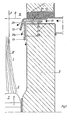
- Fig. 1 is a partial view of a cross section of a combustion chamber 1 is shown, in the lower part, the combustion zone 3, a grate 5 is provided for receiving a combustible material, such as waste 7.
- a secondary air supply channel 11 is provided in a radially projecting manner, which projects through the wall 9 and to which, for example, a ceramic felt layer 13 adjoins upwards.
- the channel 11 opens into a combustion chamber section 15 located on the exhaust side with respect to the actual combustion zone 3.
- An upper boundary plate 17 of the secondary air supply channel 11, preferably made of chromium-nickel steel, is bent toward the combustion zone 3.
- the secondary air supply duct 11 is further subdivided by a divider plate 19 into an upper duct 21a and a lower one 21b, the divider plate 19 being bent practically at a right angle at the level of the duct mouth into the combustion chamber, but at a distance from the wall 9 along the latter protrudes below.
- the secondary air supply duct 11 is delimited by the wall 9, for example covered with a cover plate 23.
- the divider plate 19 is fixed thereon by means of spacer brackets 25, a further spacer bracket 27 supporting it against the upper channel boundary plate 17.
- the latter In the bending zone of the upper duct plate 17, the latter has an outlet opening 29.
- the air flow supplied through the secondary air supply duct 11 becomes at the divider plate 19 in the upper 21a and lower 21b duct divided, depending on the dimensioning of the spacers 25 and 27, which is selected according to the requirements.
- the air flow in the lower duct 21b sweeps downward along the wall 9 against the combustion zone 3 and thus, as indicated at 31, causes the rising smoke gases to be centered around a combustion chamber axis indicated at A.
- several of the secondary air inlets shown are provided radially, at the same height around the combustion chamber 1, in order to generate a symmetrical, uniform core zone of the gases 31.
- the wall 9 in the area between combustion zone 3 and section 15 of the combustion chamber with the secondary air inlets is designed as a double wall.
- the secondary air is led into a wall space 33 at the level of the combustion zone 3, there sweeps upwards along the inner wall 9a and the outer wall 9b, both preferably covered with steel plates 23a, 23b, to the already described secondary air inlet projecting radially against the combustion chamber 1.
- the side of the inner wall 9a delimiting the intermediate space 33 is preferably provided with ribs 35 which enlarge the surface. In this arrangement, the effect of Intermediate space 33 with the ribs 35 ensures optimal cooling of the inner wall part 9a facing the combustion chamber 1.
- the supplied secondary air is preheated at the level of the combustion zone 3, so that it emerges preheated from the channels 29, 21a and 21b, which in turn has a favorable effect on the flue gas combustion.
- the secondary air inlet according to the invention, here designated as a whole by 37.
- the secondary air is first led through the building wall 39 through a supply line 41 in the area of the secondary air inlet 37.
- the line 41 then opens into an air supply and insulation chamber 43 running down the wall 39, which in the region of the combustion zone 3 opens radially inwards into an inner chamber 45 leading upwards and finally opening into the secondary air inlet 37.
- the wall separating the inner chamber 45 from the combustion chamber 1 preferably consists of a ceramic material and is covered with a steel plate 47 on the side facing the chamber 45.
- surface-increasing longitudinal ribs 35 are also provided here.
- the partition between the insulation chamber 43 and the upwardly extending chamber 45 is formed by a steel plate 49, the side of the wall 39 delimiting the insulation chamber 43 also being provided with a steel cladding 51.
- the air flow in this arrangement is again indicated by arrows.
- This wall structure provides optimal insulation of the ver combustion chamber 1 against the wall, for example the building wall 39, the secondary air in turn being successively heated on its way through the chambers 43, 45 to the secondary air inlet 37.
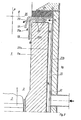
- a feed line 53 opens into a first chamber 55.
- the chamber 55 opens towards the combustion chamber 1 into a further chamber 57, which extends along the chamber 55 upwards, then again radially to the part of the chamber 55 facing away from the combustion chamber 1, finally runs axially upwards again and there into the secondary air inlet 37 opens.
- the structure of the chambers 55, 57 consists of steel plates and is supported on a foundation part 59 of the incineration plant, both chambers 55, 57 being dimensioned such that they also radially occupy the entire width of the combustion wall 9.
- the boundary plate of the chamber 57 facing the combustion chamber simultaneously forms the inner combustion chamber wall area in its area and is provided with surface-increasing ribs 35 in the chamber 57.
- the chambers 55, 57, as well as possibly a plurality of supply channels 11, the secondary air inlets 37 with the plates 17, 19 forming the outlet are expanded in the radial direction as required. This can be seen in particular from FIG. 6 to be described below.
- FIG. 5 shows a further embodiment variant of a secondary air inlet into a combustion chamber 1, the wall 9 of which is provided with steam pipes 10 as a steam boiler wall.
- a secondary air supply 59 passes between the steam pipes 10 and opens on the combustion chamber side into a radially more or less extensive supply duct 12.
- the feed channel 12, formed from steel plates, runs, as mentioned, radially, ie parallel to the grate 5 along the wall 9, in particular its upper and lateral surface facing the combustion chamber 1 being protected with a ceramic covering 61.
- the channel 12 On its side facing the combustion zone 3, the channel 12 has an outlet opening, which is preferably also radially more or less extensive, formed on the one hand by a channel wall end section 63 which is guided downwards at a distance parallel to the steam pipes 10, and on the other hand to form a first nozzle-shaped outlet 65 in Direction of the axes of the steam pipes 10, through a second, preferably thicker steel plate 67, forming the combustion chamber-side boundary of the outlet 65.
- the plate 67 is angled in an L-shape, its shorter L-leg being fastened to the part of the duct 12 on the combustion zone side.
- the plate 67 To form a second outlet 69, the plate 67 is directly in the area of its kink, respectively.
- the combustion chamber-side plate 73 is bent towards the combustion chamber axis A in its combustion zone-facing end section, with the result that the outlet 69 has a reduced axial component in the direction of the combustion zone 3 with respect to the outlet 65.
- the combustion chamber-side plate 73 is also L-shaped and rests with its one L-leg on the combustion zone-side wall of the channel 12, wherein it has an opening 75 in its kink area, connecting the outlet 69 to the combustion chamber 1 radially.
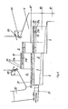
- FIG. 6 schematically shows a longitudinal section through an incinerator provided with secondary air inlets according to the invention.
- the combustion material 7 lies on a step-like grate 5, which can be pushed from an inlet zone 79 into an ejection zone 81 by means of a chute arrangement 77.
- the combustion material for example garbage, is poured through an inlet pipe 83 and pushed to the first grate level with the stoker 77.
- the fired material pre-burned on the first grate level 5 is conveyed by the grate movement in a known manner for further combustion to the next levels.
- a plurality of secondary air inlets 37 are arranged in each case in the combustion chamber wall 9, parallel to the grate steps, designed as described with reference to FIGS. 1 to 4.
- a second secondary air inlet row 87 is provided at each grate level above a first secondary air inlet row 85.
- FIG. 7 which shows a cross section through the combustion chamber 1, it is entirely possible to provide secondary air inlets 37 according to the invention in a first cross-sectional plane with exit directions primarily directed axially towards the combustion zone 3, in an overlying cross-sectional plane with exit directions primarily directed in the exit direction .
- Wall protection is thus achieved above the upper secondary air inlets 37, with the secondary air components directed upwards along the combustion chamber wall 9, and on the other hand further mixing and combustion in the ascending smoke gas core zone.
Abstract
Description
Die vorliegende Erfindung betrifft ein Verfahren zur Sekundärluftzuführung an eine abzugseitige Partie eines Verbrennungsraumes mit einer Verbrennungszone, bei welchem an der Partie-Peripherie Sekundärluft dem Raum zugeführt wird, einen Sekundärlufteinlass zur Ausführung des Verfahrens sowie eine Verwendung des Verfahrens an einer Müllverbrennungsanlage.The present invention relates to a method for supplying secondary air to a section of a combustion chamber with a combustion zone, in which secondary air is supplied to the room at the periphery of the part, a secondary air inlet for carrying out the method, and use of the method in a waste incineration plant.
Es sind derartige Verfahren bekannt, beispielsweise bei Müllverbrennungsanlagen, bei welchen Sekundärluft an bezüglich einer Verbrennungszone abzugseitigen Raumpartien, beispielsweise mittels Düsen, eingeblasen wird. Die Primärluft wird durch einen das Brenngut tragenden Rost in der Verbrennungszone zugeführt. Dabei sind des öftern die Wandungen des Verbrennungsraumes und insbe- sondere der erwähnten abzugseitigen Partie, mit entsprechenden Rohrleitungen versehen, als Dampfkessel ausgebildet. Trotz der auf bekannte Art und Weise zugeführten Sekundärluft stellt die Verbrennung der aufsteigenden Gase grosse Probleme, indem eine unvollständige Verbrennung zu Korrosionsproblemen und Verschlackungsproblemen, insbesondere von Kesselrohren und generell der Verbrennungsraumwandung, führt. Ganz generell ist bei derartigen Verbrennungen nicht nur der Brenngutverbrennung, sondern auch der entstehenden Rauchgase grösste Aufmerksamkeit zu schenken.Methods of this type are known, for example in waste incineration plants, in which secondary air is blown into parts of the room on the fume hood side, for example by means of nozzles. The primary air is supplied through a grate in the combustion zone that supports the material to be burned. The walls of the combustion chamber and, in particular , the section on the fume cupboard mentioned above, provided with appropriate pipelines, are often designed as steam boilers. Despite the secondary air supplied in a known manner, the combustion of the ascending gases poses great problems in that an incomplete combustion leads to corrosion problems and slagging problems, in particular of boiler pipes and generally the wall of the combustion chamber. In general, in the case of such burns, not only the combustion of combustion material, but also the flue gases that are generated must be given the greatest attention.
Die vorliegende Erfindung setzt sich zum Ziel ein Verfahren eingangs genannter Art so weiterzubilden, dass eine optimale Rauchgasverbrennung unter minimaler Beeinträchtigung der Verbrennungsraumwände erfolgt.The aim of the present invention is to develop a method of the type mentioned at the outset in such a way that optimum flue gas combustion takes place with minimal impairment of the combustion chamber walls.
Dies wird dadurch erreicht, dass man an der Peripherie Sekundärluft in mindestens zwei Richtungen zuführt, wobei die eine eine mit Bezug auf eine Partie-Längsachse grössere Axialkomponente gegen die Verbrennungszone hin aufweist als die andere.This is achieved by supplying secondary air to the periphery in at least two directions, one of which has a larger axial component towards the combustion zone than the other with respect to a longitudinal axis of the batch.
Durch Zuführen der Sekundärluft in Richtung mit grösserer Axialkomponente werden Rauchgase und Feuer von der Verbrennungsraumwandung in eine resultierende heisse Kernzone abgedrängt, in der, durchmischt mit Sekundärluft, alle unverbrannten Gase während ihres Abzugweges verbrennen, dabei jedoch nicht mit der Verbrennungsraumwandung in Kontakt treten. Zwischen der heissen Kernzone und den Verbrennungsraumwänden entsteht eine heisse, sauerstoffreiche Zone, welche einerseits einen guten Wärmeübergang, insbesondere wichtig für den Betrieb eines Dampfkessels, und anderseits einen guten Korrosionsschutz der Wände ergibt. Da jedoch das Zusammendrängen der Verbrennungsgase mittels eines Sekundärluftmantels in der erwähnten achsialen Richtung die Gefahr in sich birgt, dass diese Gase gerade gegen die Verbrennungsraumwände zurückschlagen, womit wiederum Verschlackung auftreten würde, wird wie erwähnt vorgeschlagen, dass zusätzlich Sekundärluft in einer zweiten Richtung zugeführt wird, mit einer geringeren Axialkomponente gegen die Verbrennungszone hin.By supplying the secondary air in the direction with a larger axial component, flue gases and fire are forced out of the combustion chamber wall into a resulting hot core zone, in which, mixed with secondary air, all unburned gases burn during their exhaust route, but do not come into contact with the combustion chamber wall. A hot, oxygen-rich zone is created between the hot core zone and the combustion chamber walls, which on the one hand provides good heat transfer, particularly important for the operation of a steam boiler, and on the other hand provides good corrosion protection for the walls. However, since the compression of the combustion gases by means of a secondary air jacket in the axial direction mentioned carries the risk that these gases will strike back against the walls of the combustion chamber, which in turn would lead to slagging, it is suggested, as mentioned, that additional secondary air is supplied in a second direction, with a lower axial component towards the combustion zone.
Damit sich die beiden Sekundärluftzuführungen gegenseitig nicht beeinträchtigen, wird vorgeschlagen, dass man die Zufuhr mit grösserer Axialrichtungskomponente näher an der Verbrennungszone vornimmt als die Zufuhr in anderer Richtung.So that the two secondary air feeds do not interfere with one another, it is proposed that the supply with a larger axial direction component is made closer to the combustion zone than the supply in another direction.
An einer abzugseitigen Partie eines Verbrennungsraumes mit einer bezüglich der Partielängsachse nahezu senkrechten Bodenpartie für das Brenngut in der Verbrennungszone wird vorgeschlagen, dass man die Zufuhr mit grösserer Axialrichtungskomponente mindestens nahezu senkrecht zur Bodenpartie wählt, womit praktisch ein zylinderartiger Sekundärluftmantel zwischen die Verbrennungsgase und die Verbrennungsraumwände gelegt wird. Dies unabhängig von einer möglichen achsialen Konizität des Verbrennungsraumes. Anderseits ist es aber auch möglich, dass man die Zufuhr mit grösserer Axialrichtungskomponente mindestens nahezu parallel zur Mantellinienrichtung der Peripherie wählt, womit insbesondere bei konischen Raumwandungen der erwähnte Sekundärluftmantel unmittelbar im Wandungsbereich erzeugt wird.On a fume cupboard section of a combustion chamber with a floor section for the material to be burned in the combustion zone that is almost perpendicular with respect to the longitudinal axis of the section, it is proposed that the supply with a larger axial direction component be selected at least almost perpendicular to the floor section, which practically places a cylinder-like secondary air jacket between the combustion gases and the combustion chamber walls . This is independent of a possible axial taper of the combustion chamber. On the other hand, it is also possible that the supply with a larger axial direction component is selected at least almost parallel to the circumferential line direction of the periphery, whereby the secondary air jacket mentioned is generated directly in the wall area, in particular in the case of conical room walls.
In manchen Fällen ist es angezeigt, den Gasrückschlag gegen die Wandung zusätzlich dadurch zu verhindern, dass man Sekundärluft in einer weiteren Richtung zu-. führt, mit einer bezüglich der zwei Richtungen kleineren Axialkomponente gegen die Verbrennungszone hin. Man kann sich den Effekt der Sekundärluftzufuhr mit kleineren Axialkomponenten so vorstellen, dass der mit der Sekundärluft grösster Axialrichtungskomponente vorerst erzeugte Kern in Abzugrichtung zusammengehalten wird, wobei gleichzeitig eine optimale Durchmischung erzielt wird. Vorzugsweise führt man diese Sekundärluft,verteilt in mindestens einer Querschnittsebene der Peripherie zu, zur Erzeugung eines am Wandungsumfang regelmässig verteilten Sekundärluftmantels. Je nach Auslegung der Verbrennungsanlage wird jedoch diese Sekundärluftzufuhr in verschiedenen übereinander liegenden Querschnittsebenen vorgenommen.In some cases it is advisable to additionally prevent the gas kicking back against the wall by adding secondary air in a further direction. leads, with an axial component smaller with respect to the two directions, towards the combustion zone. The effect of the secondary air supply with smaller axial components can be imagined in such a way that the core initially generated with the secondary air component, which is the largest in the axial direction, is held together in the withdrawal direction, with optimum mixing being achieved at the same time. This secondary air, distributed in at least one cross-sectional plane, is preferably fed to the periphery to produce one on the wall scope of regularly distributed secondary air jacket. Depending on the design of the incinerator, however, this secondary air supply is carried out in different cross-sectional levels.
Ein Sekundärlufteinlass zur Ausführung des Verfahrens zeichnet sich durch eine Luftstromaufteilanordnung aus. Sie umfasst dabei vorzugsweise einen Zuführkanal sowie mindestens einen vorzugsweise plattenförmigen, den Kanal unverteilend in diesen einragenden Teiler, wobei mindestens eine Kanalwandendpartie vorzugsweise plattenförmig mit einer Teilerendpartie einen Austritt in der einen Richtung bilden, die Teilerendpartie anderseits Teil eines Austritts in anderer Richtung bildet. Diese Ausbildung des Sekundärlufteinlasses ermöglicht eine einfache, optimal mit Verbrennungsraumwänden zu kombinierende Struktur, wobei die Ausbildung in bevorzugter Art und Weise mit einem plattenförmigen Teiler und einer plattenförmigen Kanalwandendpartie auch eine optimale Sekundärluftverteilung in radialer Verbrennungsraumrichtung ermöglicht. Selbstverständlich kann jedoch die Luftstromaufteilanordnung auch durch eine Mehrzahl entsprechend gerichteter, herkömmlicher Düsen realisiert sein.A secondary air inlet for carrying out the method is characterized by an airflow distribution arrangement. It preferably comprises a feed channel and at least one preferably plate-shaped divider which projects the channel in a non-distributive manner, at least one channel wall end section, preferably plate-shaped with a divider end section, forming an outlet in one direction and the divider end section forming part of an outlet in the other direction. This design of the secondary air inlet enables a simple structure that can be optimally combined with combustion chamber walls, the design in a preferred manner with a plate-shaped divider and a plate-shaped duct wall end section also enabling optimal secondary air distribution in the radial direction of the combustion chamber. Of course, however, the airflow distribution arrangement can also be implemented by a plurality of appropriately directed, conventional nozzles.
Zur gezielten Ausrichtung der Sekundärluftzufuhr wird dabei vorzugsweise mindestens die eine Kanalwandendpartie umgebogen, ebenso die Teilerendpartie, wobei bezüglich einer Kanallängsachse die Kanalwandendpartie weniger, die Teilerendpartie mehr umgebogen ist, so dass letztere mit der Kanalwandendpartie einen Austritt in mit Bezug auf diese Achse kleinerem sowie mit einem weiteren Wandungsteil einen Austritt mit diesbezüglich grösserem Richtungswinkel festlegt. Dadurch wird der Teiler und insbesondere dessen Endpartie als Teil der Austritte für beide Richtungen verwendet; der eine Austritt entsteht zwischen Teilerendpartie und Kanalwandendpartie, der zweite zwischen Teilerendpartie und allenfalls einer weiteren Kanalwandendpartie oder direkt der Verbrennungsraumwandung.For the targeted alignment of the secondary air supply, at least one duct wall end section is preferably bent, as is the divider end section, with the duct wall end section being bent less with respect to a longitudinal duct axis, and the divider end section being bent more so that the latter with the duct wall end section has an exit with respect to this axis which is smaller and with one another wall part defines an outlet with a larger directional angle in this regard. This will divide and in particular, its end part is used as part of the exits for both directions; one emerges between the divider end section and the duct wall end section, the second between the divider end section and possibly a further duct wall end section or directly the combustion chamber wall.
Zur Erzeugung eines weiteren Sekundärluftstromes in dritter Richtung wird vorgeschlagen, dass im Umbiegebereich der Kanalwandendpartie eine Durchtrittöffnung vorgesehen ist, bezüglich der Kanalachse einen kleineren Winkel einschliessend als die Kanalwandendpartie. Damit wird die zwischen Teiler und Kanalwand- endpartie ausströmende Luft nochmals durch die nun ebenfalls als Teiler wirkende Kanalwandendpartie aufgeteilt und strömt in einer dritten Richtung aus.To generate a further secondary air flow in the third direction, it is proposed that a passage opening be provided in the bending region of the duct wall end section, enclosing a smaller angle with respect to the duct axis than the duct wall end section. The air flowing out between the divider and the end of the duct wall is again divided by the end of the duct wall now also acting as a divider and flows out in a third direction.
Je nach Einsatz kann auch eine Luftaufteilanordnung vorgesehen werden, die einen Zuführkanal umfasst, wobei in dessen Austrittsbereich mindestens eine Partie der Kanalwandung doppelwandig ausgeführt ist, wobei in der inneren Wandung, und allenfalls der äusseren, eine Durchtritts- allenfalls Austrittsöffnung für die Sekundärluft vorgesehen ist. Eine Oeffnung in der inneren Wandung ermöglicht einen Luftaustritt vom Kanalinnenraum in den Kanalzwischenraum und damit eine entsprechende Luftstromkomponentenrichtung, wobei die allenfalls vorgesehene zusätzliche Oeffnung in der äusseren Kanalwandung für Austritt der Sekundärluft in dritter Richtung sorgt. Vorzugsweise werden bei allen Ausführungsvarianten das Aufteilverhältnis durch variable Positionierung mindestens eines Teilers in einem Zuführkanal eingestellt, beispielsweise durch Einsatz unterschiedlich dimensionierter Distanzhalterungen für den Teiler.Depending on the application, an air distribution arrangement can also be provided, which comprises a supply duct, at least one part of the duct wall being double-walled in its outlet area, with a through-opening or at most an outlet opening for the secondary air being provided in the inner wall, and possibly the outer wall. An opening in the inner wall enables air to escape from the interior of the duct into the space between the ducts and thus a corresponding direction of the airflow components, the additional opening provided in the outer duct wall, if any, ensuring that the secondary air escapes in the third direction. In all of the design variants, the division ratio is preferably set by variable positioning of at least one divider in a feed channel, for example by using spacers of different dimensions for the divider.
Die Erfindung wird anschliessend beispielsweise anhand von Figuren erläutert.The invention is subsequently explained, for example, using figures.
Es zeigen:
- Fig. 1 einen Schnitt durch eine Verbrennungsraumwandung, mit einem erfindungsgemässen Sekundärlufteinlass,
- Fig. 2 eine Darstellung analog zu Fig. 1 an einem doppelwandigen Wandabschnitt,
- Fig. 3 eine Darstellung analog zu Fig. 1 mit einer weiteren Sekundärluftzufuhrvariante zum erfindungsgemässen Sekundärlufteinlass,
- Fig. 4 eine weitere Ausführungsform, dargestellt analog zu Fig. 1 der Sekundärluftzuführung,
- Fig. 5 einen Schnitt durch eine als Kesselraumwand ausgebildete Wandung mit dem erfindungsgemässen Sekundärlufteinlass,
- Fig. 6 eine schematische Längsschnitt-Darstellung einer Müllverbrennungsanlage mit erfindungsgemässer Sekundärluftzufuhr,
- Fig. 7 eine Querschnitt-Darstellung durch einen Verbrennungsraum mit erfindungsgemässen Sekundärlufteinlässen in zwei Verbrennungsraumebenen.
- 1 shows a section through a combustion chamber wall, with a secondary air inlet according to the invention,
- 2 shows a representation analogous to FIG. 1 on a double-walled wall section,
- 3 shows a representation analogous to FIG. 1 with a further secondary air supply variant for the secondary air inlet according to the invention,
- 4 shows a further embodiment, shown analogously to FIG. 1 of the secondary air supply,
- 5 shows a section through a wall designed as a boiler room wall with the secondary air inlet according to the invention,
- 6 shows a schematic longitudinal section of a waste incineration plant with a secondary air supply according to the invention,
- 7 shows a cross section through a combustion chamber with secondary air inlets according to the invention in two combustion chamber levels.
In Fig. 1 ist eine Teilansicht eines Querschnittes eines Verbrennungsraumes 1 dargestellt, in dessen unterem Teil, der Verbrennungszone 3, ein Rost 5 für die Aufnahme eines Brenngutes, wie Müll 7, vorgesehen ist. In der Seitenwandung 9 des Verbrennungsraumes 1 ist radial einragend mindestens ein Sekundärluftzuführkanal 11 vorgesehen, der durch die Wand 9 hindurchragt und an den, gegen oben, beispielsweise eine keramische Filzschicht 13 anschliesst. Der Kanal 11 mündet in eine bezüglich der eigentlichen Verbrennungszone 3 abzugseitig gelegene Verbrennungsraumpartie 15. Eine obere Berandungsplatte 17 des Sekundärluftzuführkanals 11, vorzugsweise aus Chromnickelstahl, ist gegen die Verbrennungszone 3 hin umgebogen. Ausmündungsseitig ist der Sekundärluftzuführkanal 11 im weiteren durch eine Teilerplatte 19 in einen oberen Kanal 21a und einen unteren 21b unterteilt, wobei die Teilerplatte 19 auf der Höhe der Kanalausmündung in den Verbrennungsraum praktisch rechtwinklig umgebogen ist, jedoch mit Abstand bezüglich der Wand 9, letzterer entlang nach unten ragt. Unten ist der Sekundärluftzuführkanal 11 durch die Wandung 9 begrenzt, beispielsweise mit einer Deckplatte 23 belegt. Mittels Distanzhalterungen 25 ist darauf die Teilerplatte 19 fixiert, wobei eine weitere Distanzhalterung 27 sie gegen die obere Kanalberandungsplatte 17 abstützt.In Fig. 1 is a partial view of a cross section of a
In der Umbiegezone der oberen Kanalplatte 17 weist letztere eine Austrittsöffnung 29 auf. Wie mit Pfeilen angedeutet, wird der durch den Sekundärluftzuführkanal 11 zugeführte Luftstrom an der Teilerplatte 19 in den oberen 21a und unteren 21b Kanal aufgeteilt, je nach Dimensionierung der Distanzhalterungen 25 und 27, die entsprechend den Erfordernissen gewählt wird. Der Luftstrom im unteren Kanal 21b streicht bei Austritt entlang der Wandung 9 nach unten gegen die Verbrennungszone 3 und bewirkt so, wie bei 31 angedeutet, eine Zentrierung der aufsteigenden Rauchgase um eine bei A angedeutete Verbrennungsraumachse. Der Luftstrom, der aus dem oberen Kanal 21a streicht, und ebenso der Luftstrom, der in dritter Richtung aus der Austrittsöffnung 29, als dritter Kanal wirkend, austritt, verhindert ein Zurückschlagen der Rauchgase 31 an die Wandung 9 im Bereich des Sekundärlufteinlasses. Vorzugsweise werden radial, auf gleicher Höhe um den Verbrennungsraum 1 herum verteilt, mehrere der dargestellten Sekundärlufteinlässe vorgesehen, um eine symmetrische, gleichmässige Kernzone der Gase 31 zu erzeugen.In the bending zone of the
In Fig. 2, bei welcher mit Bezug auf Fig. 1 sich entsprechende Teile mit den gleichen Positionszeichen versehen sind, ist die Wandung 9 im Bereich zwischen Verbrennungszone 3 und Partie 15 des Verbrennungsraumes mit den Sekundärlufteinlässen als Doppelwand ausgeführt. Die Sekundärluft wird auf Höhe der Verbrennungszone 3 in einen Wandungszwischenraum 33 geführt, streicht dort entlang der Innenwandung 9a und der Aussenwandung 9b, beide vorzugsweise mit Stahlplatten 23a, 23b belegt, nach oben, hin zum radial gegen den Verbrennungsraum 1 einragenden, bereits beschriebenen Sekundärlufteinlass. Die den Zwischenraum 33 begrenzende Seite der Innenwand 9a ist dabei vorzugsweise mit oberflächenvergrössernden Rippen 35 versehen. Bei dieser Anordnung ist durch Wirkung des Zwischenraumes 33 mit den Rippen 35 eine optimale Kühlung der dem Verbrennungsraum 1 zugekehrten Innenwandpartie 9a sichergestellt. Zudem wird die zugeführte Sekundärluft auf Höhe der Verbrennungszone 3 vorgewärmt, so dass sie aus den Kanälen 29, 21a und 21b vorgewärmt austritt, was wiederum die Rauchgasverbrennung günstig beeinflusst.In FIG. 2, in which corresponding parts are provided with the same position symbols with reference to FIG. 1, the
In Fig. 3 ist wiederum der erfindungsgemässe Sekun- därlufteinlass, hier als Ganzes mit 37 bezeichnet, dargestellt. Zur Verringerung der Abstrahlungsverluste nach aussen, beispielsweise in eine Gebäudewandung 39, wird die Sekundärluft erst durch eine Zuführleitung 41 im Bereiche des Sekundärlufteinlasses 37 durch die Gebäudewandung 39 geführt. Die Leitung 41 mündet darauf in eine der Wandung 39 entlang nach unten verlaufende Luftzufuhr- und Isolationskammer 43, welche im Bereich der Verbrennungszone 3 radial nach innen in eine nach oben führende, schliesslich in den Sekundärlufteinlass 37 einmündende, innere Kammer 45 mündet. Die die innere Kammer 45 vom Verbrennungsraum 1 trennende Wand besteht vorzugsweise aus einem keramischen Material und ist an der der Kammer 45 zugekehrten Seite mit einer Stahlplatte 47 belegt. Es sind, wie bereits in Fig. 2 beschrieben, auch hier oberflächenvergrössernde Längsrippen 35 vorgesehen. Die Trennwand zwischen Isolationskammer 43 und nach oben verlaufender Kammer 45 wird durch eine Stahlplatte 49 gebildet, wobei auch die die Isolationskammer 43 begrenzende Seite der Wandung 39 mit einer Stahlverkleidung 51 versehen ist. Der Luftstrom in dieser Anordnung ist wiederum mit Pfeilen angedeutet. Diese Wandstruktur ergibt eine optimale Isolation des Verbrennungsraumes 1 gegen die Wandung, z.B. die Gebäudewandung 39, wobei wiederum die Sekundärluft auf ihrem Wege durch die Kammern 43, 45 zum Sekundärluft- einlass 37 sukzessive erwärmt wird.3 again shows the secondary air inlet according to the invention, here designated as a whole by 37. To reduce the radiation losses to the outside, for example into a
Gemäss Fig. 4 mündet eine Zuführleitung 53 in eine erste Kammer 55 ein. Verbrennungszonenseitig mündet die Kammer 55 gegen den Verbrennungsraum 1 hin in eine weitere Kammer 57, die sich entlang der Kammer 55 nach oben, dann wiederum radial zur dem Verbrennungsraum 1 abgekehrten Partie der Kammer 55 erstreckt, schliesslich wieder axial nach oben verläuft und dort in den Sekundärlufteinlass 37 mündet. Die Struktur der Kammern 55, 57 besteht aus Stahlplatten, ist auf einem Fundamentteil 59 der Verbrennungsanlage abgestützt, wobei beide Kammern 55, 57 so dimensioniert sind, dass sie auch radial die ganze Breite der Verbrennungswand 9 einnehmen. Die dem Verbrennungsraum zugekehrte Begrenzungsplatte der Kammer 57 bildet gleichzeitig in ihrem Bereich die innere Verbrennungsraumwandpartie und ist, in der Kammer 57 mit oberflächenvergrössernden Rippen 35 versehen. Die Kammern 55, 57, ebenso wie allenfalls mehrere Zuführkanäle 11, die Sekundärlufteinlässe 37 mit den Austritt bildenden Platten 17, 19 sind je nach Erfordernissen in radialer Richtung ausgedehnt. Dies wird insbesondere aus der im weiteren zu beschreibenden Fig. 6 ersichtlich.4, a
In allen anhand der Figuren 1 bis 4 dargestellten Sekundärlufteinlässen wird die Luftverteilung in die erfindungsgemässen, unterschiedlichen Austrittsrichtungen durch entsprechende Umbiegung einerseits einer Zuführkanalaussenwandpartie 17 und anderseits der Teilerplatte 19 mit Bezug auf eine Zuführkanalachse B bewirkt.In all of the secondary air inlets shown with reference to FIGS. 1 to 4, the air distribution in the different outlet directions according to the invention becomes one on the one hand by appropriate bending Feed channel
In Fig. 5 ist eine weitere Ausführungsvariante eines Sekundärlufteinlasses in einen Vrbrennungsraum 1 dargestellt, dessen Wandung 9 als Dampfkesselwand mit Dampfrohren 10 versehen ist. Eine Sekundärluftzuführung 59 tritt zwischen den Dampfrohren 10 durch und mündet verbrennungsraumseitig in einen radial mehr oder weniger ausgedehnten Zuführkanal 12 ein. Der Zuführkanal 12, aus Stahlplatten gebildet, läuft, wie erwähnt, radial, d.h. parallel zum Rost 5 entlang der Wand 9, wobei insbesondere seine obere und seitliche, dem Verbrennungsraum 1 zugekehrte Fläche mit einem Keramikbelag 61 geschützt sind. Auf seiner der Verbrennungszone 3 zugekehrten Seite weist der Kanal 12 eine vorzugsweise ebenfalls radial mehr oder weniger ausgedehnte Austrittsöffnung auf, einerseits gebildet durch eine auf Abstand parallel zu den Dampfrohren 10 nach unten geführte Kanalwandendpartie 63, plattenförmig, anderseits zur Bildung eines ersten stutzenförmigen Austrittes 65 in Richtung der Achsen der Dampfrohre 10, durch eine zweite, vorzugsweise dicker dimensionierte Stahlplatte 67, die verbrennungsraumseitige Berandung des Austrittes 65 bildend. Hierzu ist die Platte 67 L-förmig abgewinkelt, wobei ihr kürzerer L-Schenkel an der verbrennungszonenseitigen Partie des Kanals 12 befestigt ist. Zur Bildung eines zweiten Austrittes 69 ist die Platte 67 unmittelbar im Bereich ihrer Knickung resp. ihrer Befestigung am Kanal 12 mit einer Durchbrechung 71 versehen, die, mit einer Ausrichtungskomponente axial gegen die Verbrennungszone 3 hin, den Sekundärluft- übertritt aus der Anfangszone des Austrittes 65 in den durch die Platte 67 und eine zweite, ihr bezüglich auf Abstand gehaltene, verbrennungsraumseitige Platte 73, gebildeten zweiten Austritt 69 ermöglicht. Die verbrennungsraumseitige Platte 73 ist in ihrem verbrennungszonenzugekehrten Endabschnitt gegen die Verbrennungsraumachse A hin aufgeknickt, womit der Austritt 69 mit Bezug auf den Austritt 65 eine reduzierte Axialkomponente in Richtung zur Verbrennungszone 3 hin aufweist. Die verbrennungsraumseitige Platte 73 ist ebenfalls L-förmig ausgebildet und liegt mit ihrem einen L-Schenkel an der verbrennungszonenseitigen Wandung des Kanals 12 an, wobei sie in ihrem Abknickungsbereich eine Durchbrechung 75 aufweist, radial den Austritt 69 mit dem Verbrennungsraum 1 verbindend. Damit wird ein weiterer Austritt für die Sekundärluft, nun in praktisch radialer Richtung, realisiert. Die Strömungsrichtungen der Sekundärluft sind wiederum mit Pfeilen dargestellt. Bei dieser Ausführungsvariante ist die Endpartie resp. Austrittspartie des Zuführkanals 12 mit den Platten 67 und 73 doppelwandig ausgebildet, wobei entsprechend vorgesehene Durchbrechungen 71 für die Sekundärluftaufteilung sorgen.5 shows a further embodiment variant of a secondary air inlet into a
In Fig. 6 ist schematisch ein Längsschnitt durch eine mit erfindungsgemässen Sekundärlufteinlässen versehene Verbrennungsanlage dargestellt. Auf einem treppenförmig abgestuften Rost 5 liegt das Verbrennungsgut 7, welches mittels einer Schüranordnung 77 aus einer Einlasszone 79 in eine Auswurfzone 81 geschoben werden kann. Das Verbrennungsgut, beispielsweise Müll, wird durch ein Einlassrohr 83 eingeschüttet und mit der Schürvorrichtung 77 auf die erste Roststufe geschoben. Das auf der ersten Roststufe 5 vorverbrannte Brenngut wird durch die Rostbewegung in bekannter Art und Weise zur Weiterverbrennung auf die nächstfolgenden Stufen gefördert. Parallel zu den Roststufen ist in der Verbrennungsraumwandung 9 je eine Mehrzahl Sekundärlufteinlässe 37 angeordnet, ausgebildet wie anhand der Fig. 1 bis 4 beschrieben. Oberhalb einer ersten Sekundärlufteinlassreihe 85 ist an jeder Roststufe eine zweite Sekundärlufteinlassreihe 87 vorgesehen. Oberhalb der zweiten Sekundärlufteinlassreihe 87 sind im weiteren sekundärlufteinblasende Düsen 89 vorgesehen, ebenfalls zur Zentrierung des nicht dargestellten Rauchgaskerns, deren Korrosionsschutz durch bei 91 schematisch dargestellte, erfindungsgemässe Sekundärlufteinlässe sichergestellt ist.6 schematically shows a longitudinal section through an incinerator provided with secondary air inlets according to the invention. The
Wie aus Fig. 7 ersichtlich, die einen Querschnitt durch den Verbrennungsraum 1 darstellt, ist es durchaus möglich, erfindungsgemässe Sekundärlufteinlässe 37 in einer ersten Querschnittsebene mit vornehmlich axial gegen die Verbrennungszone 3 hin gerichteten Austrittsrichtungen vorzusehen, in einer darüberliegenden Querschnittsebene mit vornehmlich in Austrittsrichtung gerichteten Austrittsrichtungen. Damit wird auch oberhalb der oberen Sekundärlufteinlässe 37, mit den nach oben der Verbrennungsraumwandung 9 entlang gerichteten Sekundärluftkomponenten, einerseits ein Wandschutz erzielt, anderseits eine weitere Durchmischung und Verbrennung in der aufsteigenden Rauchgaskernzone.As can be seen from FIG. 7, which shows a cross section through the
Mit dem anhand verschiedener Aufbau- und Einsatzbeispiele dargestellten Sekundärlufteinlass wird das Konzept des erfindungsgemässen Verfahrens realisiert, durch welches eine optimale Rauchgasverbrennung auf dem Austrittsweg erzielt wird und zudem, durch Abdrängen der Gase in eine Kernzone, ein optimaler Wandschutz.The concept of the method according to the invention is realized with the secondary air inlet illustrated on the basis of various construction and application examples, by means of which optimal flue gas combustion is achieved on the exit path and, by displacing the gases into a core zone, optimal wall protection.
Die Vielzahl der Einsatzmöglichkeiten und Einbaumöglichkeiten des erfindungsgemässen Konzepts wurde anhand der Auswahl gemäss Fig. 1 bis 7 dargelegt.The large number of possible uses and installation options for the concept according to the invention was explained on the basis of the selection according to FIGS. 1 to 7.
Claims (13)
Applications Claiming Priority (2)
| Application Number | Priority Date | Filing Date | Title |
|---|---|---|---|
| CH276683A CH665468A5 (en) | 1983-05-20 | 1983-05-20 | METHOD FOR SECONDARY AIR SUPPLY, SECONDARY AIR INLET FOR PERFORMING THE METHOD AND APPLICATION OF THE METHOD. |
| CH2766/83 | 1983-05-20 |
Publications (1)
| Publication Number | Publication Date |
|---|---|
| EP0126920A1 true EP0126920A1 (en) | 1984-12-05 |
Family
ID=4241129
Family Applications (1)
| Application Number | Title | Priority Date | Filing Date |
|---|---|---|---|
| EP84103941A Withdrawn EP0126920A1 (en) | 1983-05-20 | 1984-04-09 | Method of injecting secondary air, secondary air entrance for carrying out said process and the use of said process |
Country Status (2)
| Country | Link |
|---|---|
| EP (1) | EP0126920A1 (en) |
| CH (1) | CH665468A5 (en) |
Cited By (3)
| Publication number | Priority date | Publication date | Assignee | Title |
|---|---|---|---|---|
| AT390206B (en) * | 1988-04-22 | 1990-04-10 | Howorka Franz | DEVICE FOR THE THERMAL DISASSEMBLY OF FLUID POLLUTANTS |
| EP0496094A2 (en) * | 1991-01-24 | 1992-07-29 | MARTIN GmbH für Umwelt- und Energietechnik | Nozzle for feeding secondary air |
| WO2016119069A1 (en) * | 2015-01-30 | 2016-08-04 | Mokesys Ag | Air feed-in device for a combustion furnace |
Families Citing this family (1)
| Publication number | Priority date | Publication date | Assignee | Title |
|---|---|---|---|---|
| SE461295B (en) * | 1988-06-14 | 1990-01-29 | Hultgren Karl S H | DEVICE FOR COMBUSTION OF FIXED FUEL, PROVIDED WITH INSTALLATION ORGANIZED IN THE BRAENN CHAMBER FOR CONTROL OF SUPPLY OF COMBUSTION AIR |
Citations (7)
| Publication number | Priority date | Publication date | Assignee | Title |
|---|---|---|---|---|
| GB191223057A (en) * | 1911-10-10 | 1913-04-03 | Karl Schleyder | Improvements in and relating to the Furnaces of Steam Generators and other Furnaces. |
| US1464299A (en) * | 1921-02-03 | 1923-08-07 | Swartz Henry | Coal-gas carburetor |
| US1569811A (en) * | 1924-12-12 | 1926-01-12 | Jordan Ernest | Air heater for furnaces |
| CH138546A (en) * | 1929-01-12 | 1930-03-15 | Schroeder Charles | Device for the injection of secondary hot air into the fireplaces. |
| FR809562A (en) * | 1936-08-06 | 1937-03-06 | Device applicable to water tube boilers | |
| DE654851C (en) * | 1935-05-15 | 1937-12-31 | Alexandre Germeau | Box-shaped air preheater to be installed in furnaces |
| DE3038875A1 (en) * | 1980-10-15 | 1982-06-03 | Vereinigte Kesselwerke AG, 4000 Düsseldorf | WASTE COMBUSTION PLANT |
-
1983
- 1983-05-20 CH CH276683A patent/CH665468A5/en not_active IP Right Cessation
-
1984
- 1984-04-09 EP EP84103941A patent/EP0126920A1/en not_active Withdrawn
Patent Citations (7)
| Publication number | Priority date | Publication date | Assignee | Title |
|---|---|---|---|---|
| GB191223057A (en) * | 1911-10-10 | 1913-04-03 | Karl Schleyder | Improvements in and relating to the Furnaces of Steam Generators and other Furnaces. |
| US1464299A (en) * | 1921-02-03 | 1923-08-07 | Swartz Henry | Coal-gas carburetor |
| US1569811A (en) * | 1924-12-12 | 1926-01-12 | Jordan Ernest | Air heater for furnaces |
| CH138546A (en) * | 1929-01-12 | 1930-03-15 | Schroeder Charles | Device for the injection of secondary hot air into the fireplaces. |
| DE654851C (en) * | 1935-05-15 | 1937-12-31 | Alexandre Germeau | Box-shaped air preheater to be installed in furnaces |
| FR809562A (en) * | 1936-08-06 | 1937-03-06 | Device applicable to water tube boilers | |
| DE3038875A1 (en) * | 1980-10-15 | 1982-06-03 | Vereinigte Kesselwerke AG, 4000 Düsseldorf | WASTE COMBUSTION PLANT |
Cited By (5)
| Publication number | Priority date | Publication date | Assignee | Title |
|---|---|---|---|---|
| AT390206B (en) * | 1988-04-22 | 1990-04-10 | Howorka Franz | DEVICE FOR THE THERMAL DISASSEMBLY OF FLUID POLLUTANTS |
| EP0496094A2 (en) * | 1991-01-24 | 1992-07-29 | MARTIN GmbH für Umwelt- und Energietechnik | Nozzle for feeding secondary air |
| EP0496094A3 (en) * | 1991-01-24 | 1992-12-23 | Martin Gmbh Fuer Umwelt- Und Energietechnik | Method and nozzle for feeding secondary air |
| WO2016119069A1 (en) * | 2015-01-30 | 2016-08-04 | Mokesys Ag | Air feed-in device for a combustion furnace |
| CH710683A1 (en) * | 2015-01-30 | 2016-08-15 | Mokesys Ag | Device for feeding air into the combustion chamber of a combustion furnace. |
Also Published As
| Publication number | Publication date |
|---|---|
| CH665468A5 (en) | 1988-05-13 |
Similar Documents
| Publication | Publication Date | Title |
|---|---|---|
| DE3038875C2 (en) | Waste incineration plant | |
| WO1984001014A1 (en) | Method and installation for operating a stoker-heater | |
| DE60013307T2 (en) | INJECTION NOZZLE FOR SUPPLYING COMBUSTIBLE FABRIC INTO A BOILER | |
| EP0839301B1 (en) | Method of incinerating material | |
| DE2063628B2 (en) | Incinerator for waste oil | |
| EP0798510B1 (en) | Heating boiler | |
| EP0126920A1 (en) | Method of injecting secondary air, secondary air entrance for carrying out said process and the use of said process | |
| DE3105099A1 (en) | COMBUSTION DEVICE | |
| DE3320709A1 (en) | ELECTRIC BURNER FOR OXIDIZING OVENS | |
| DE3813441A1 (en) | Grating bar element for a thrust grating furnace for refuse incineration | |
| EP0387859A2 (en) | Heating boiler | |
| WO1982000331A1 (en) | Hot gas generator | |
| DE102005001907B4 (en) | Process and installation for burning a fuel | |
| DE2807166C2 (en) | ||
| DE10158299A1 (en) | Water tube boiler | |
| DE2164122A1 (en) | Exhaust gas incineration system | |
| DE4426357A1 (en) | Furnace arrangement for solid fuels such as refuse, and combustion process | |
| DE1804020A1 (en) | Boiler for hot water heating | |
| DE3931580C2 (en) | ||
| EP1002993B1 (en) | Boiler for liquid fuels | |
| EP0209703A2 (en) | Glow insert for furnaces, in particular for boilers, and furnace equipped with such a glow insert | |
| DE2650089A1 (en) | Secondary combustion plant using discharge fan - enables gases from primary combustion chamber to be transferred to radiation zone of plant | |
| DE1985665U (en) | DRUM-SHAPED GRILL FOR WASTE INCINERATION DEVICES. | |
| DE3521043A1 (en) | Furnace, in particular heating boiler | |
| DE202017001363U1 (en) | biomass furnace |
Legal Events
| Date | Code | Title | Description |
|---|---|---|---|
| PUAI | Public reference made under article 153(3) epc to a published international application that has entered the european phase |
Free format text: ORIGINAL CODE: 0009012 |
|
| AK | Designated contracting states |
Designated state(s): AT BE CH DE FR GB IT LI LU NL SE |
|
| STAA | Information on the status of an ep patent application or granted ep patent |
Free format text: STATUS: THE APPLICATION IS DEEMED TO BE WITHDRAWN |
|
| 18D | Application deemed to be withdrawn |
Effective date: 19850806 |