EP0126722A2 - Plant for processing organic material - Google Patents
Plant for processing organic material Download PDFInfo
- Publication number
- EP0126722A2 EP0126722A2 EP19840850155 EP84850155A EP0126722A2 EP 0126722 A2 EP0126722 A2 EP 0126722A2 EP 19840850155 EP19840850155 EP 19840850155 EP 84850155 A EP84850155 A EP 84850155A EP 0126722 A2 EP0126722 A2 EP 0126722A2
- Authority
- EP
- European Patent Office
- Prior art keywords
- liquid phase
- plant
- contaminated
- filter
- container
- Prior art date
- Legal status (The legal status is an assumption and is not a legal conclusion. Google has not performed a legal analysis and makes no representation as to the accuracy of the status listed.)
- Withdrawn
Links
Images


Classifications
-
- C—CHEMISTRY; METALLURGY
- C12—BIOCHEMISTRY; BEER; SPIRITS; WINE; VINEGAR; MICROBIOLOGY; ENZYMOLOGY; MUTATION OR GENETIC ENGINEERING
- C12M—APPARATUS FOR ENZYMOLOGY OR MICROBIOLOGY; APPARATUS FOR CULTURING MICROORGANISMS FOR PRODUCING BIOMASS, FOR GROWING CELLS OR FOR OBTAINING FERMENTATION OR METABOLIC PRODUCTS, i.e. BIOREACTORS OR FERMENTERS
- C12M21/00—Bioreactors or fermenters specially adapted for specific uses
- C12M21/04—Bioreactors or fermenters specially adapted for specific uses for producing gas, e.g. biogas
-
- C—CHEMISTRY; METALLURGY
- C12—BIOCHEMISTRY; BEER; SPIRITS; WINE; VINEGAR; MICROBIOLOGY; ENZYMOLOGY; MUTATION OR GENETIC ENGINEERING
- C12M—APPARATUS FOR ENZYMOLOGY OR MICROBIOLOGY; APPARATUS FOR CULTURING MICROORGANISMS FOR PRODUCING BIOMASS, FOR GROWING CELLS OR FOR OBTAINING FERMENTATION OR METABOLIC PRODUCTS, i.e. BIOREACTORS OR FERMENTERS
- C12M23/00—Constructional details, e.g. recesses, hinges
- C12M23/36—Means for collection or storage of gas; Gas holders
-
- C—CHEMISTRY; METALLURGY
- C12—BIOCHEMISTRY; BEER; SPIRITS; WINE; VINEGAR; MICROBIOLOGY; ENZYMOLOGY; MUTATION OR GENETIC ENGINEERING
- C12M—APPARATUS FOR ENZYMOLOGY OR MICROBIOLOGY; APPARATUS FOR CULTURING MICROORGANISMS FOR PRODUCING BIOMASS, FOR GROWING CELLS OR FOR OBTAINING FERMENTATION OR METABOLIC PRODUCTS, i.e. BIOREACTORS OR FERMENTERS
- C12M25/00—Means for supporting, enclosing or fixing the microorganisms, e.g. immunocoatings
- C12M25/16—Particles; Beads; Granular material; Encapsulation
-
- C—CHEMISTRY; METALLURGY
- C12—BIOCHEMISTRY; BEER; SPIRITS; WINE; VINEGAR; MICROBIOLOGY; ENZYMOLOGY; MUTATION OR GENETIC ENGINEERING
- C12M—APPARATUS FOR ENZYMOLOGY OR MICROBIOLOGY; APPARATUS FOR CULTURING MICROORGANISMS FOR PRODUCING BIOMASS, FOR GROWING CELLS OR FOR OBTAINING FERMENTATION OR METABOLIC PRODUCTS, i.e. BIOREACTORS OR FERMENTERS
- C12M29/00—Means for introduction, extraction or recirculation of materials, e.g. pumps
- C12M29/02—Percolation
-
- Y—GENERAL TAGGING OF NEW TECHNOLOGICAL DEVELOPMENTS; GENERAL TAGGING OF CROSS-SECTIONAL TECHNOLOGIES SPANNING OVER SEVERAL SECTIONS OF THE IPC; TECHNICAL SUBJECTS COVERED BY FORMER USPC CROSS-REFERENCE ART COLLECTIONS [XRACs] AND DIGESTS
- Y02—TECHNOLOGIES OR APPLICATIONS FOR MITIGATION OR ADAPTATION AGAINST CLIMATE CHANGE
- Y02E—REDUCTION OF GREENHOUSE GAS [GHG] EMISSIONS, RELATED TO ENERGY GENERATION, TRANSMISSION OR DISTRIBUTION
- Y02E50/00—Technologies for the production of fuel of non-fossil origin
- Y02E50/30—Fuel from waste, e.g. synthetic alcohol or diesel
-
- Y—GENERAL TAGGING OF NEW TECHNOLOGICAL DEVELOPMENTS; GENERAL TAGGING OF CROSS-SECTIONAL TECHNOLOGIES SPANNING OVER SEVERAL SECTIONS OF THE IPC; TECHNICAL SUBJECTS COVERED BY FORMER USPC CROSS-REFERENCE ART COLLECTIONS [XRACs] AND DIGESTS
- Y02—TECHNOLOGIES OR APPLICATIONS FOR MITIGATION OR ADAPTATION AGAINST CLIMATE CHANGE
- Y02W—CLIMATE CHANGE MITIGATION TECHNOLOGIES RELATED TO WASTEWATER TREATMENT OR WASTE MANAGEMENT
- Y02W30/00—Technologies for solid waste management
- Y02W30/40—Bio-organic fraction processing; Production of fertilisers from the organic fraction of waste or refuse
Definitions
- This invention relates to a plant for processing organic material, preferably pig manure and the like, which contains liquid and solid phases.
- Pig farms having average and big pig populations yield very large amounts of manure which for the greater part contains a liquid phase (urine), the remainder being a solid phase (droppings) which includes bedding and the like.
- manure has to be taken care of and can thus be processed in a biogas reactor in which anaerobic bacteria are added to the manure to generate biogas which mainly contains methane and can be used as an energy source for the operation of gas boilers, engines, power supply units etc. and for the formation of digested sludge which is a useful landfill material and/or fertilizer.
- the biogas reactor because of the large proportion of liquid phase in the manure is not as highly effective as would be desirable, since a complete treatment of the manure will require an unacceptably long dwell time.
- thermophilic temperature range at about 45-60 o C, but this treatment is sensitive to stoppages and requires a costly heating of the manure.
- the object of the present invention is to provide a plant which is of a novel and efficiency increasing construction to eliminate the drawbacks outlined in the foregoing.
- this plant comprises an anaerobic filter for purification of the contaminated liquid phase, and a recirculator for receiving the contaminated liquid phase and the liquid phase purified in the filter and for mixing, according to need, the contaminated liquid phase with a large or small quantity of the purified liquid phase, said mixture being supplied to the filter and the remainder of the purified liquid phase being conducted to say a recipient.
- the plant further comprises a separator for separating the contaminated liquid and solid phases from one another, the contaminated liquid phase being led, as mentioned above, to the recirculator, while the contaminated solid phase is discharged for processing preferably to a biogas reactor, the biogas generated in the reactor being collected for use, while the solid phase treated in the reactor may be supplied to a thickener/drier for conversion into a sludge for land filling, deposition, composting, fertilizing and like purposes.
- the plant according to the invention for processing pig manure which is illustrated by way of a flow diagram in Fig. 1, comprises five main stages, viz.: separation 1, purification 2, recirculation 3, stabilisation 4 and separation 5.
- the separation stage 1 includes a separator 6, see Figs. 2 and 3, which comprises an upright container 8 placed on the ground 7 and having a cylindrical circumferential wall 9, a roof 10 and a conically tapering bottom 11.
- the container 8 is placed on columns 12 which are embedded or otherwise fixed in a foundation plate 13 on the ground 7 or in cesspit walls.
- the container 8 has an inlet 14 which is connected via a conduit 15 to a submersible pump 16.
- the pump 16 is placed on the bottom of a cesspit 17 in which manure 18 is collected from one or more pig houses (not shown).
- the manure 18 in the cesspit 17 is pumped by means of the pump 16 through the conduit 15 and inlet 14 to the container 8 of the separator 6, in which container the contaminated liquid and solid phases 19 and 20, respectively, are separated from one another by sedimentation.
- the excess manure can be returned to the cesspit 17 through a conduit 21.
- the separated contaminated solid phase 20 is discharged through an outlet 22 at the bottom 11 of the container 8 and is supplied by means of a pump 23 and through a conduit 24 to the stabilisation stage 4 for treatment in a manner to be described more in detail below.
- the contaminated liquid phase 19 in turn is led through an outlet 25 and a conduit 26 to the recirculation and purification stages 3, 2 for treatment in a manner to be described more in detail below.
- the outlet 25 has several vertically spaced points 27 for tapping of the container 8. These tapping points are controllable by means of valves 28 so as to open and close for withdrawal of the contaminated liquid phase 19 at different levels of the container 8 as close to the surface 29 in the container 8 as possible, depending on the quantity filled thereinto. Withdrawing the contaminated liquid phase 19 in this manner, one obtains a calm laminar flow of said phase to the tapping point 27 concerned.
- the purification stage 2 includes an anaerobic filter 30 for purification of the contaminated liquid phase 19.
- the filter 30 is of the continuously operating type and comprises an upright container 31 having a cylindrical circumferential wall 32, a roof 33 and a bottom 34.
- the container 31 is placed on columns 35 which in turn are embedded or otherwise fixed in a foundation 36 on the ground 7.
- the container 31 of the anaerobic filter 30 contains a bed 37 of hollow or solid, relatively large bodies 38 carrying anaerobic bacteria on their surfaces, which bacteria form a so-called bio- skin on said surfaces.
- the bodies 38 are rod-shaped, but it should be pointed out that the bodies can have any optional shape.
- the bed 37 is supported on a netting 37 of expanded metal, which is spaced some distance upwardly from the bottom 34 of the container 31, as will appear from Fig. 6.
- the anaerobic filter 30 is supplied with a mixture 40, to be described more in detail below, of contaminated liquid phase 19 and already purified liquid phase 41.
- the supply of the mixture 40 takes place beneath the bed 37 and is brought about by means of several supply pipes 42 uniformly distributed around the container 31 and having their one ends connected to a manifold 43 which is disposed around the container 31.
- said supply pipes 42 extend obliquely upwardly towards the center of the container 31, the inclination amounting to about 1:10 in the case illustrated.
- the supply pipes 42 are connected to the manifold 43 there are arranged manually or automatically operated valves 44 for connection of an optional number of supply pipes 42.
- the supply pipes 42 have several downwardly opening outlets 81, see Fig. 9.
- the mixture 40 When urged in an upward direction through the bed 37 the mixture 40 is purified by the action of the anaerobic bacteria on the bodies 38, the biogas 45 generated collecting in the upper portion of the container 31 and being discharged for use through a gas pipe 46.
- a manhole 47 with water seal is provided in the roof 33 of the container 31 to permit inspection of the interior of the container.
- the water seal also serves as a safety valve against excess pressure in the container 31.
- a collecting trough 48 which is horizontally placed directly above the bed 37, in the embodiment illustrated.
- the collecting trough 48 is open in an upward direction and connected at one end via a water seal (not shown) to a discharge pipe 49 for the purified liquid phase 41.
- an outlet 50 which is connected to the earlier described cesspit 17 through a conduit 51 and which serves to clean the anaerobic filter 30.
- said recirculation stage includes a recirculator 52.
- the recirculator has a container 53 of rectangular cross-section and is preferably made of concrete with side walls 54 and a bottom 55.
- the container 53 is also placed on the ground 7, either directly or via a foundation (not shown).
- the container 53 is divided into two chambers 56, 57 by means of a partition 58 between two opposite side walls 54.
- the first chamber 56 in one of the side walls 54 has an inlet 59 which is connected via the conduit 26 to the outlet 25 of the separator 6 so as to receive the contaminated liquid phase 19 therefrom.
- an outlet 60 which is connected via a feed pipe 61 to the manifold 43 of the anaerobic filter 30 for supply of the mixture 40.
- a feed pump 62 is installed in the feed pipe 61 for positive feed of the mixture 40 to the filter 30.
- a protective netting 63 is arranged around the outlet 60 to prevent solid impurities, if any, from entering the filter 30.
- the second chamber 57 has an inlet 64 which is connected via the discharge pipe 49 to the collecting trough 48 of the anaerobic filter 30 so as to receive the purified liquid'phase 41 therefrom.
- a check valve 65 with a flap 66 is inserted in the partition 58 and opens towards the first chamber 56. Said check valve permits the purified liquid phase coming from the filter 30 through the inlet 64 to flow from the second chamber 57 to the first chamber 56, but prevents a flow from the first chamber 56 to the second chamber 57.
- the check valve 65 is of such a design that say two thirds of the purified liquid phase 41 from the filter 30 flow into the first chamber 56 to mix with the contaminated liquid phase 19 coming from the separator 6 through the inlet 59 so that the mixture 40 is formed, which is to be supplied to the anaerobic filter 30.
- the remainder of the purified liquid phase 41 is conducted via an outlet 67 in the side wall 54 of the second chamber 57 which is opposed to the inlet 64, and via a conduit 68 to a recipient (not shown) or to for example one or more aerobic filters for further treatment therein, if considered necessary.
- An overflow 69 is arranged between the inlet 64 and the outlet 67 of the second chamber 57 to provide the desired flow of the purified liquid phase 41 from the second chamber 57 to the first chamber 56 through the check valve 65.
- Said overflow extends between the partition 58 and the opposite side wall 54 and has its upper edge 70 placed on a higher level than the check valve 65, as will appear from Fig. 5.
- a further outlet 71 is provided in one of the side walls 54 of that chamber, said outlet 71 being connected to the cesspit 17 through a conduit 72.
- the stabilisation stage 4 includes a biogas reactor for stabilising treatment of the contaminated solid phase 20 coming from the separator 6 through the conduit 4.
- the biogas reactor is of conventional construction and function and as it is not in itself part of the present invention, its construction and function will not be described more in detail.
- the biogas 73 generated in the biogas reactor is collected in a similar manner as the biogas 45 from the anaerobic filter 30 and is conducted for this purpose through a conduit to a place of use.
- the solid phase 75 stabilised in the biogas reactor is fed through a conduit to a thickener/drier, for example a sludge press, comprised in the separation stage 5. This thickener/drier is also of conventional construction and function and need not therefore be described more in detail.
- the solid phase 75 is converted into a sludge 77 which can be used for various purposes, for example landfilling, deposition, composting, fertilizing etc.
- the excess liquid 78 from the thickening/drying process is conducted through a conduit 79 to the recirculator 52, more precisely the first chamber 56 thereof, via an inlet 80 to permit mixing this liquid with the earlier mixture 40 of contaminated liquid phase 19 and purified liquid phase 41.
Abstract
Description
- This invention relates to a plant for processing organic material, preferably pig manure and the like, which contains liquid and solid phases.
- Pig farms having average and big pig populations yield very large amounts of manure which for the greater part contains a liquid phase (urine), the remainder being a solid phase (droppings) which includes bedding and the like. Such manure has to be taken care of and can thus be processed in a biogas reactor in which anaerobic bacteria are added to the manure to generate biogas which mainly contains methane and can be used as an energy source for the operation of gas boilers, engines, power supply units etc. and for the formation of digested sludge which is a useful landfill material and/or fertilizer.
- Owing to the large amounts of manure the biogas reactor with the pertaining peripheral equipment has to be given a corresponding size, which necessitates large economical and structural investments.
- Moreover, the biogas reactor because of the large proportion of liquid phase in the manure is not as highly effective as would be desirable, since a complete treatment of the manure will require an unacceptably long dwell time.
- For greater efficiency it would therefore be possible to carry out the treatment in the thermophilic temperature range at about 45-60oC, but this treatment is sensitive to stoppages and requires a costly heating of the manure.
- Therefore, the object of the present invention is to provide a plant which is of a novel and efficiency increasing construction to eliminate the drawbacks outlined in the foregoing.
- According to the invention, this plant comprises an anaerobic filter for purification of the contaminated liquid phase, and a recirculator for receiving the contaminated liquid phase and the liquid phase purified in the filter and for mixing, according to need, the contaminated liquid phase with a large or small quantity of the purified liquid phase, said mixture being supplied to the filter and the remainder of the purified liquid phase being conducted to say a recipient. The plant further comprises a separator for separating the contaminated liquid and solid phases from one another, the contaminated liquid phase being led, as mentioned above, to the recirculator, while the contaminated solid phase is discharged for processing preferably to a biogas reactor, the biogas generated in the reactor being collected for use, while the solid phase treated in the reactor may be supplied to a thickener/drier for conversion into a sludge for land filling, deposition, composting, fertilizing and like purposes.
- A specially preferred embodiment of a processing plant according to the invention will now be described in the following with reference to the accompanying drawings. In the drawings:
- Fig. 1 is a flow diagram of the plant;
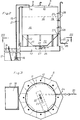
- Fig. 2 is a side view of a separator comprised in the plant;
- Fig. 3 is a cross-section taken on line III-III in Fig. 2;
- Fig. 4 is a top plan view of a recirculator comprised in the plant;
- Fig. 5 is a section on line V-V in Fig. 4;
- Fig. 6 is a side view of an anaerobic filter of the plant;
- Fig. 7 is a cross-section on line VII-VII in Fig. 6; and
- Figs. 8 and 9 are sections on lines VIII-VIII and IX-IX, respectively, in Fig. 7.
- The plant according to the invention for processing pig manure, which is illustrated by way of a flow diagram in Fig. 1, comprises five main stages, viz.:
separation 1, purification 2,recirculation 3,stabilisation 4 andseparation 5. - The
separation stage 1 includes aseparator 6, see Figs. 2 and 3, which comprises an upright container 8 placed on theground 7 and having a cylindrical circumferential wall 9, aroof 10 and a conically taperingbottom 11. In the embodiment illustrated, the container 8 is placed oncolumns 12 which are embedded or otherwise fixed in afoundation plate 13 on theground 7 or in cesspit walls. - In the
roof 10 the container 8 has an inlet 14 which is connected via aconduit 15 to asubmersible pump 16. Thepump 16 is placed on the bottom of acesspit 17 in whichmanure 18 is collected from one or more pig houses (not shown). Themanure 18 in thecesspit 17 is pumped by means of thepump 16 through theconduit 15 and inlet 14 to the container 8 of theseparator 6, in which container the contaminated liquid andsolid phases cesspit 17 through aconduit 21. - The separated contaminated
solid phase 20 is discharged through anoutlet 22 at thebottom 11 of the container 8 and is supplied by means of apump 23 and through aconduit 24 to thestabilisation stage 4 for treatment in a manner to be described more in detail below. - The contaminated
liquid phase 19 in turn is led through anoutlet 25 and aconduit 26 to the recirculation andpurification stages 3, 2 for treatment in a manner to be described more in detail below. In the embodiment according to Fig. 2, theoutlet 25 has several vertically spacedpoints 27 for tapping of the container 8. These tapping points are controllable by means ofvalves 28 so as to open and close for withdrawal of the contaminatedliquid phase 19 at different levels of the container 8 as close to thesurface 29 in the container 8 as possible, depending on the quantity filled thereinto. Withdrawing the contaminatedliquid phase 19 in this manner, one obtains a calm laminar flow of said phase to thetapping point 27 concerned. - The purification stage 2 includes an
anaerobic filter 30 for purification of the contaminatedliquid phase 19. Thefilter 30 is of the continuously operating type and comprises anupright container 31 having a cylindricalcircumferential wall 32, a roof 33 and a bottom 34. Thecontainer 31 is placed oncolumns 35 which in turn are embedded or otherwise fixed in a foundation 36 on theground 7. Thecontainer 31 of theanaerobic filter 30 contains abed 37 of hollow or solid, relativelylarge bodies 38 carrying anaerobic bacteria on their surfaces, which bacteria form a so-called bio- skin on said surfaces. As will appear from the magnification to the right in Fig. 6, thebodies 38 are rod-shaped, but it should be pointed out that the bodies can have any optional shape. Thebed 37 is supported on anetting 37 of expanded metal, which is spaced some distance upwardly from the bottom 34 of thecontainer 31, as will appear from Fig. 6. - The
anaerobic filter 30 is supplied with amixture 40, to be described more in detail below, of contaminatedliquid phase 19 and already purifiedliquid phase 41. The supply of themixture 40 takes place beneath thebed 37 and is brought about by means ofseveral supply pipes 42 uniformly distributed around thecontainer 31 and having their one ends connected to amanifold 43 which is disposed around thecontainer 31. As will appear from Figs. 6 and 9, saidsupply pipes 42 extend obliquely upwardly towards the center of thecontainer 31, the inclination amounting to about 1:10 in the case illustrated. Where thesupply pipes 42 are connected to themanifold 43 there are arranged manually or automatically operatedvalves 44 for connection of an optional number ofsupply pipes 42. To dispense themixture 40 thesupply pipes 42 have several downwardly openingoutlets 81, see Fig. 9. - When urged in an upward direction through the
bed 37 themixture 40 is purified by the action of the anaerobic bacteria on thebodies 38, thebiogas 45 generated collecting in the upper portion of thecontainer 31 and being discharged for use through agas pipe 46. - A
manhole 47 with water seal is provided in the roof 33 of thecontainer 31 to permit inspection of the interior of the container. In addition to being a gas seal the water seal also serves as a safety valve against excess pressure in thecontainer 31. - Withdrawal of the
liquid phase 41 purified in thebed 37 takes place, as will appear from Fig. 6, over the bed by means of a collectingtrough 48, see also Fig. 8, which is horizontally placed directly above thebed 37, in the embodiment illustrated. The collectingtrough 48 is open in an upward direction and connected at one end via a water seal (not shown) to adischarge pipe 49 for the purifiedliquid phase 41. - At the lowermost point of the bottom 34 there is arranged an outlet 50 which is connected to the earlier described
cesspit 17 through aconduit 51 and which serves to clean theanaerobic filter 30. - As earlier mentioned, there is a
recirculation stage 3 between theseparation stage 1 and the purification stage 2. In the embodiment illustrated, said recirculation stage includes arecirculator 52. The recirculator has acontainer 53 of rectangular cross-section and is preferably made of concrete withside walls 54 and abottom 55. Thecontainer 53 is also placed on theground 7, either directly or via a foundation (not shown). Thecontainer 53 is divided into twochambers partition 58 between twoopposite side walls 54. Thefirst chamber 56 in one of theside walls 54 has aninlet 59 which is connected via theconduit 26 to theoutlet 25 of theseparator 6 so as to receive the contaminatedliquid phase 19 therefrom. In theside wall 54 of thefirst chamber 56 which is opposed to theinlet 59 there is provided anoutlet 60 which is connected via afeed pipe 61 to themanifold 43 of theanaerobic filter 30 for supply of themixture 40. Afeed pump 62 is installed in thefeed pipe 61 for positive feed of themixture 40 to thefilter 30. Aprotective netting 63 is arranged around theoutlet 60 to prevent solid impurities, if any, from entering thefilter 30. Thesecond chamber 57 has aninlet 64 which is connected via thedischarge pipe 49 to the collectingtrough 48 of theanaerobic filter 30 so as to receive the purified liquid'phase 41 therefrom. Acheck valve 65 with aflap 66 is inserted in thepartition 58 and opens towards thefirst chamber 56. Said check valve permits the purified liquid phase coming from thefilter 30 through theinlet 64 to flow from thesecond chamber 57 to thefirst chamber 56, but prevents a flow from thefirst chamber 56 to thesecond chamber 57. - The
check valve 65 is of such a design that say two thirds of the purifiedliquid phase 41 from thefilter 30 flow into thefirst chamber 56 to mix with the contaminatedliquid phase 19 coming from theseparator 6 through theinlet 59 so that themixture 40 is formed, which is to be supplied to theanaerobic filter 30. The remainder of the purifiedliquid phase 41 is conducted via anoutlet 67 in theside wall 54 of thesecond chamber 57 which is opposed to theinlet 64, and via aconduit 68 to a recipient (not shown) or to for example one or more aerobic filters for further treatment therein, if considered necessary. - An
overflow 69 is arranged between theinlet 64 and theoutlet 67 of thesecond chamber 57 to provide the desired flow of the purifiedliquid phase 41 from thesecond chamber 57 to thefirst chamber 56 through thecheck valve 65. Said overflow extends between thepartition 58 and theopposite side wall 54 and has itsupper edge 70 placed on a higher level than thecheck valve 65, as will appear from Fig. 5. - To prevent overcharging of the first chamber 56 a
further outlet 71 is provided in one of theside walls 54 of that chamber, saidoutlet 71 being connected to thecesspit 17 through aconduit 72. - - The
stabilisation stage 4 includes a biogas reactor for stabilising treatment of the contaminatedsolid phase 20 coming from theseparator 6 through theconduit 4. The biogas reactor is of conventional construction and function and as it is not in itself part of the present invention, its construction and function will not be described more in detail. Thebiogas 73 generated in the biogas reactor is collected in a similar manner as thebiogas 45 from theanaerobic filter 30 and is conducted for this purpose through a conduit to a place of use. Thesolid phase 75 stabilised in the biogas reactor is fed through a conduit to a thickener/drier, for example a sludge press, comprised in theseparation stage 5. This thickener/drier is also of conventional construction and function and need not therefore be described more in detail. In the thickener/drier thesolid phase 75 is converted into asludge 77 which can be used for various purposes, for example landfilling, deposition, composting, fertilizing etc. The excess liquid 78 from the thickening/drying process is conducted through aconduit 79 to therecirculator 52, more precisely thefirst chamber 56 thereof, via aninlet 80 to permit mixing this liquid with theearlier mixture 40 of contaminatedliquid phase 19 and purifiedliquid phase 41. - A specifically preferred embodiment of the plant according to the invention has been illustrated and described in the foregoing, but nothing prevents the plant from being designed in another manner within the scope of the patent protection solicited. Neither is the plant necessarily restricted to the processing of pig manure, but in principle equally useful for processing other organic materials which contain liquid and preferably also solid phases.
Claims (15)
Applications Claiming Priority (2)
| Application Number | Priority Date | Filing Date | Title |
|---|---|---|---|
| GB8314250A GB2140402B (en) | 1983-05-23 | 1983-05-23 | Plant for processing organic material |
| GB8314250 | 1983-05-23 |
Publications (2)
| Publication Number | Publication Date |
|---|---|
| EP0126722A2 true EP0126722A2 (en) | 1984-11-28 |
| EP0126722A3 EP0126722A3 (en) | 1986-04-16 |
Family
ID=10543217
Family Applications (1)
| Application Number | Title | Priority Date | Filing Date |
|---|---|---|---|
| EP19840850155 Withdrawn EP0126722A3 (en) | 1983-05-23 | 1984-05-17 | Plant for processing organic material |
Country Status (7)
| Country | Link |
|---|---|
| EP (1) | EP0126722A3 (en) |
| JP (1) | JPS605294A (en) |
| AU (1) | AU2847884A (en) |
| CA (1) | CA1232150A (en) |
| DK (1) | DK250784A (en) |
| ES (1) | ES8600648A1 (en) |
| GB (1) | GB2140402B (en) |
Cited By (7)
| Publication number | Priority date | Publication date | Assignee | Title |
|---|---|---|---|---|
| EP0286100A1 (en) * | 1987-04-08 | 1988-10-12 | Rea Gesellschaft Für Recycling Von Energie Und Abfall Mbh | Process and plant for the treatment and anaerobic digestion of biogenic wastes |
| DE4120808A1 (en) * | 1991-06-24 | 1993-01-14 | Recycling Energie Abfall | REPROCESSING OF WASTE FOR ANAEROBIC PLANNING OF ORGANIC BIOGENIC COMPONENTS OF WASTE, ESPECIALLY OF BIOMUELL, WET WASTE, RESIDUAL WASTE AND COMMERCIAL WASTE |
| US5455773A (en) * | 1993-03-31 | 1995-10-03 | Maschinenfabrik Muller-Weingarten Ag | Method for the determination of optimum parameters for a casting process, particularly on die-casting machines |
| US7005068B2 (en) * | 2001-02-20 | 2006-02-28 | Hoffland Environmental, Inc. | Method and apparatus for treating animal waste and wastewater |
| DE102007004892A1 (en) * | 2007-01-05 | 2008-07-10 | Reinhart von Dr.-Ing. Nordenskjöld | Process and device for the treatment of organic residues from biogas plants |
| DE102007004135A1 (en) * | 2007-01-26 | 2008-08-07 | Volkmar Dertmann | Method for fermenting paste-like biomass, particularly brewer grains from brewery or alcohol production, under anaerobic conditions, involves guiding biomass into fermentation container in batch or continuous process |
| DE102010050863A1 (en) * | 2010-11-04 | 2012-05-10 | Mt-Energie Gmbh | Apparatus for mixing non-pumpable biomass with a liquid |
Families Citing this family (3)
| Publication number | Priority date | Publication date | Assignee | Title |
|---|---|---|---|---|
| FI81774C (en) * | 1987-07-03 | 1990-12-10 | Outokumpu Oy | Reactor designed to generate biogas |
| BRPI1103492A2 (en) * | 2011-07-01 | 2013-07-30 | Vale Solucoes Em En S A Vse | sustainable and integrated food chain waste processing system and process applied to the sustainable system |
| RU2542107C2 (en) * | 2013-04-16 | 2015-02-20 | Федеральное государственное бюджетное научное учреждение "Всероссийский научно-исследовательский институт электрификации сельского хозяйства" (ФГБНУ ВИЭСХ) | Device for environmentally safe recycling of organic substrates into biogas and fertilisers |
Citations (4)
| Publication number | Priority date | Publication date | Assignee | Title |
|---|---|---|---|---|
| FR2339434A1 (en) * | 1976-01-28 | 1977-08-26 | Lawson Victor | WASTE TREATMENT PROCESS |
| WO1980001922A1 (en) * | 1979-03-14 | 1980-09-18 | Saf Soc Agricole Fonciere | Process for treating manures |
| DE3049302A1 (en) * | 1980-12-29 | 1982-08-19 | Armjanskij naučno-issledovatel'skij institut mechanizacii i elektrofikacii selskogo chozjaistva, Erevan | METHOD FOR UTILIZING LIFE PRODUCTS OF ANIMALS AND SYSTEM FOR IMPLEMENTING THE SAME |
| EP0062388A1 (en) * | 1981-04-03 | 1982-10-13 | De Erven G.de Boer B.V. | A method and installation for anaerobic fermentation of liquid manure |
Family Cites Families (10)
| Publication number | Priority date | Publication date | Assignee | Title |
|---|---|---|---|---|
| GB521036A (en) * | 1938-03-29 | 1940-05-09 | Joseph Darius Griffin | Improvements in sewage sludge digestion |
| FR2270210A1 (en) * | 1974-05-09 | 1975-12-05 | Celanese Corp | |
| GB1567578A (en) * | 1976-10-29 | 1980-05-14 | Celanese Corp | Process for the treatment of aqueous organic waste streams in an anaerobic filter |
| AU4527879A (en) * | 1978-03-28 | 1979-10-04 | Coulthard, J.L. | Anaerobic filter |
| GB1599760A (en) * | 1978-05-31 | 1981-10-07 | Univ Strathclyde | Conversion of organic matter to methane fertiliser or soil conditioners |
| US4284508A (en) * | 1979-10-01 | 1981-08-18 | Jewell William J | Methane production by attached film |
| US4351729A (en) * | 1980-02-06 | 1982-09-28 | Celanese Corporation | Biological filter and process |
| NZ197992A (en) * | 1980-08-18 | 1984-07-31 | Unisearch Ltd | Anaerobic bacterial degradation of organic materials |
| AU555425B2 (en) * | 1980-09-15 | 1986-09-25 | Biotechnical Processes Inc. | Treatment of waste water producting methane |
| FR2490624A1 (en) * | 1980-09-24 | 1982-03-26 | Armor Entr Metallurg | APPARATUS FOR PROCESSING BIOCHEMICAL WASTE |
-
1983
- 1983-05-23 GB GB8314250A patent/GB2140402B/en not_active Expired
-
1984
- 1984-05-17 EP EP19840850155 patent/EP0126722A3/en not_active Withdrawn
- 1984-05-22 ES ES532692A patent/ES8600648A1/en not_active Expired
- 1984-05-22 DK DK250784A patent/DK250784A/en not_active Application Discontinuation
- 1984-05-22 CA CA000454801A patent/CA1232150A/en not_active Expired
- 1984-05-22 AU AU28478/84A patent/AU2847884A/en not_active Abandoned
- 1984-05-23 JP JP59104384A patent/JPS605294A/en active Pending
Patent Citations (4)
| Publication number | Priority date | Publication date | Assignee | Title |
|---|---|---|---|---|
| FR2339434A1 (en) * | 1976-01-28 | 1977-08-26 | Lawson Victor | WASTE TREATMENT PROCESS |
| WO1980001922A1 (en) * | 1979-03-14 | 1980-09-18 | Saf Soc Agricole Fonciere | Process for treating manures |
| DE3049302A1 (en) * | 1980-12-29 | 1982-08-19 | Armjanskij naučno-issledovatel'skij institut mechanizacii i elektrofikacii selskogo chozjaistva, Erevan | METHOD FOR UTILIZING LIFE PRODUCTS OF ANIMALS AND SYSTEM FOR IMPLEMENTING THE SAME |
| EP0062388A1 (en) * | 1981-04-03 | 1982-10-13 | De Erven G.de Boer B.V. | A method and installation for anaerobic fermentation of liquid manure |
Cited By (10)
| Publication number | Priority date | Publication date | Assignee | Title |
|---|---|---|---|---|
| EP0286100A1 (en) * | 1987-04-08 | 1988-10-12 | Rea Gesellschaft Für Recycling Von Energie Und Abfall Mbh | Process and plant for the treatment and anaerobic digestion of biogenic wastes |
| WO1988008030A1 (en) * | 1987-04-08 | 1988-10-20 | Rea Gesellschaft Für Energie Und Abfall Mit Beschr | Process and device for treatment and anaerobic fermentation of bio-organic waste |
| DE4120808A1 (en) * | 1991-06-24 | 1993-01-14 | Recycling Energie Abfall | REPROCESSING OF WASTE FOR ANAEROBIC PLANNING OF ORGANIC BIOGENIC COMPONENTS OF WASTE, ESPECIALLY OF BIOMUELL, WET WASTE, RESIDUAL WASTE AND COMMERCIAL WASTE |
| US5377917A (en) * | 1991-06-24 | 1995-01-03 | Rea Gesellschaft Fur Recycling Von Energie Und Abfall Mbh | Processing waste materials for anaerobic digestion of the biogenic-organic constituents |
| US5455773A (en) * | 1993-03-31 | 1995-10-03 | Maschinenfabrik Muller-Weingarten Ag | Method for the determination of optimum parameters for a casting process, particularly on die-casting machines |
| US7005068B2 (en) * | 2001-02-20 | 2006-02-28 | Hoffland Environmental, Inc. | Method and apparatus for treating animal waste and wastewater |
| DE102007004892A1 (en) * | 2007-01-05 | 2008-07-10 | Reinhart von Dr.-Ing. Nordenskjöld | Process and device for the treatment of organic residues from biogas plants |
| DE102007004135A1 (en) * | 2007-01-26 | 2008-08-07 | Volkmar Dertmann | Method for fermenting paste-like biomass, particularly brewer grains from brewery or alcohol production, under anaerobic conditions, involves guiding biomass into fermentation container in batch or continuous process |
| DE102010050863A1 (en) * | 2010-11-04 | 2012-05-10 | Mt-Energie Gmbh | Apparatus for mixing non-pumpable biomass with a liquid |
| DE102010050863B4 (en) * | 2010-11-04 | 2016-04-14 | MT-Energie Service GmbH | Apparatus for mixing non-pumpable biomass with a liquid |
Also Published As
| Publication number | Publication date |
|---|---|
| DK250784D0 (en) | 1984-05-22 |
| ES532692A0 (en) | 1985-09-01 |
| JPS605294A (en) | 1985-01-11 |
| ES8600648A1 (en) | 1985-09-01 |
| CA1232150A (en) | 1988-02-02 |
| EP0126722A3 (en) | 1986-04-16 |
| GB8314250D0 (en) | 1983-06-29 |
| GB2140402A (en) | 1984-11-28 |
| DK250784A (en) | 1984-11-24 |
| AU2847884A (en) | 1984-11-29 |
| GB2140402B (en) | 1987-05-28 |
Similar Documents
| Publication | Publication Date | Title |
|---|---|---|
| CN101378998B (en) | Process and reactor for anaerobic waste water purification | |
| US4121539A (en) | Animal enclosure system with waste treatment means | |
| US5507946A (en) | Apparatus for wastewater treatment | |
| US7993521B2 (en) | Plant and method for generating biogas from biologically degradable material containing liquid and solid components, in particular waste products, and a biogas generation container for use in the plant | |
| CN101823793B (en) | Double-path circulation full-mixing type anaerobic reactor | |
| KR970006920B1 (en) | Fluidized bed process | |
| EP0126722A2 (en) | Plant for processing organic material | |
| US11465922B2 (en) | Methods for anaerobic waste digestion | |
| EP0102610A1 (en) | Apparatus and method for the treatment of organic wastes | |
| SK11602000A3 (en) | Method and device for the biological treatment of a fluid with biogas generation | |
| KR960013337B1 (en) | Improved fluidized bed process and apparatus | |
| US6860997B1 (en) | Apparatus and method for processing organic materials | |
| KR101048516B1 (en) | Apparatus for anaerobic fermentation and equipment for making liquid fertilizer and purifying wastewater of livestock having the same | |
| US2331031A (en) | Digestion of sewage solids and like matter | |
| KR102299806B1 (en) | Organic Waste Disposal Devices and Methods for Organic Waste Disposal Using them | |
| JP2935540B2 (en) | Methane fermentation equipment | |
| SU1437355A1 (en) | Apparatus for fermenting liquid waste | |
| CN218931842U (en) | Sludge reduction sewage treatment system | |
| RU2073401C1 (en) | Method and device for anaerobic fermenting of liquified organic waste | |
| RU97026U1 (en) | BIOGAS COMPLEX | |
| CN208038236U (en) | A kind of integrated processing system of livestock breeding wastewater | |
| FI90970C (en) | Biogas reactor for the treatment of organic waste mass during waste management | |
| EP0062388A1 (en) | A method and installation for anaerobic fermentation of liquid manure | |
| Duncan | Sludge conditioning prior to atomized suspension technique. | |
| CN107954567A (en) | A kind of food sewage disposal system |
Legal Events
| Date | Code | Title | Description |
|---|---|---|---|
| PUAI | Public reference made under article 153(3) epc to a published international application that has entered the european phase |
Free format text: ORIGINAL CODE: 0009012 |
|
| AK | Designated contracting states |
Designated state(s): BE DE FR IT NL SE |
|
| PUAL | Search report despatched |
Free format text: ORIGINAL CODE: 0009013 |
|
| AK | Designated contracting states |
Kind code of ref document: A3 Designated state(s): BE DE FR IT NL SE |
|
| 17P | Request for examination filed |
Effective date: 19861010 |
|
| 17Q | First examination report despatched |
Effective date: 19871125 |
|
| STAA | Information on the status of an ep patent application or granted ep patent |
Free format text: STATUS: THE APPLICATION IS DEEMED TO BE WITHDRAWN |
|
| 18D | Application deemed to be withdrawn |
Effective date: 19880607 |
|
| RIN1 | Information on inventor provided before grant (corrected) |
Inventor name: POLA, ANTONIN |