EP0126536A2 - Flüssigkeitsstrahldrucker und sein mit Ultraschall betriebenes Reinigungsverfahren - Google Patents
Flüssigkeitsstrahldrucker und sein mit Ultraschall betriebenes Reinigungsverfahren Download PDFInfo
- Publication number
- EP0126536A2 EP0126536A2 EP84302318A EP84302318A EP0126536A2 EP 0126536 A2 EP0126536 A2 EP 0126536A2 EP 84302318 A EP84302318 A EP 84302318A EP 84302318 A EP84302318 A EP 84302318A EP 0126536 A2 EP0126536 A2 EP 0126536A2
- Authority
- EP
- European Patent Office
- Prior art keywords
- drive signal
- fluid
- cleaning
- reservoir
- orifice plate
- Prior art date
- Legal status (The legal status is an assumption and is not a legal conclusion. Google has not performed a legal analysis and makes no representation as to the accuracy of the status listed.)
- Granted
Links
Images
Classifications
-
- B—PERFORMING OPERATIONS; TRANSPORTING
- B41—PRINTING; LINING MACHINES; TYPEWRITERS; STAMPS
- B41J—TYPEWRITERS; SELECTIVE PRINTING MECHANISMS, i.e. MECHANISMS PRINTING OTHERWISE THAN FROM A FORME; CORRECTION OF TYPOGRAPHICAL ERRORS
- B41J2/00—Typewriters or selective printing mechanisms characterised by the printing or marking process for which they are designed
- B41J2/005—Typewriters or selective printing mechanisms characterised by the printing or marking process for which they are designed characterised by bringing liquid or particles selectively into contact with a printing material
- B41J2/01—Ink jet
- B41J2/135—Nozzles
- B41J2/165—Prevention or detection of nozzle clogging, e.g. cleaning, capping or moistening for nozzles
- B41J2/16517—Cleaning of print head nozzles
- B41J2/16552—Cleaning of print head nozzles using cleaning fluids
-
- B—PERFORMING OPERATIONS; TRANSPORTING
- B41—PRINTING; LINING MACHINES; TYPEWRITERS; STAMPS
- B41J—TYPEWRITERS; SELECTIVE PRINTING MECHANISMS, i.e. MECHANISMS PRINTING OTHERWISE THAN FROM A FORME; CORRECTION OF TYPOGRAPHICAL ERRORS
- B41J2/00—Typewriters or selective printing mechanisms characterised by the printing or marking process for which they are designed
- B41J2/005—Typewriters or selective printing mechanisms characterised by the printing or marking process for which they are designed characterised by bringing liquid or particles selectively into contact with a printing material
- B41J2/01—Ink jet
- B41J2/135—Nozzles
- B41J2/165—Prevention or detection of nozzle clogging, e.g. cleaning, capping or moistening for nozzles
- B41J2/16517—Cleaning of print head nozzles
- B41J2002/16567—Cleaning of print head nozzles using ultrasonic or vibrating means
Definitions
- the present invention relates to fluid jet systems and, more particularly, to an arrangement and method for cleaning dried ink and other contaminants from the orifice or orifices from which the jet drop streams eminate in a fluid jet device.
- Ink jet printers such as shown in U. S. Patent No. 3,701,998, issued October 31, 1972, to Mathis, are well known in which an electrically conductive fluid is supplied under pressure to a fluid receiving reservoir defined by a print head.
- the reservoir communicates with one or more orifices defined by an orifice plate, such that the fluid emerges from the orifices as fluid filaments.
- the fluid filaments break up into streams of drops.
- Selected ones of the drops are then directed by an electrical field into catch trajectories in which the drops strike drop catchers, while others of the drops are directed into print trajectories in which they are deposited upon a print receiving medium.
- traveling wave stimulation as illustrated in the above identified Mathis patent, a series of bending waves are caused to travel along the orifice plate and are coupled sequentially to each of the orifices in one or more rows of orifices.
- the entire print head is mechanically vibrated to enhance drop break up.
- jet printers of this type use a solvent based ink, such as a water based ink. It is not uncommon for particles of dried ink to become lodged in or adjacent to orifices in the fluid receiving reservoir. Additionally, since the drops which are caught and not deposited upon the print receiving medium are typically recirculated to the fluid supply system for reuse, it will be appreciated that contaminants, such as paper dust, will be ingested into the fluid supply system and may not be fully removed by a fluid filtration. These particles, as well as ink particles, may settle out and attach to various portions of the fluid supply system. The particles may subsequently break loose and migrate to other portions of the fluid supply system.
- a solvent based ink such as a water based ink.
- any of these processes may produce a particle which either blocks or partially hinders the flow of fluid through one or more orifices. It will be appreciated that where an orifice is totally blocked, the print positions on the print receiving medium which were to be serviced by the jet drop stream eminating from that orifice will not be printed and, therefore, a noticeable white strip along the print receiving medium will be produced. On the other hand, if an orifice is partially blocked, the initial trajectory of the drops produced by the orifice will typically be somewhat crooked. As a consequence, although drops from the jet drop stream eminating from the partially blocked orifice will be deposited on the print receiving medium, the positions at which the drops are deposited may not coincide precisely with the positions at which it is desired to deposit the drops.
- U. S. Patent No. 4,007,465, issued February 8, 1977, to Chaudhary discloses a fluid jet print head in which the head defines a manifold which communicates with the orifices, and two fluid supply paths at different sides of the manifold.
- One of the supply paths is located at the top of the manifold and is reversible. If air or an impurity causing a clogging of an orifice is encountered, the top path may be reversed so the fluid enters from one path and exits at the top.
- a printer which includes a means for manually overpressurizing the ink supply chamber communicating with the nozzle structure of the ink jet printer.
- the chamber When the chamber is overpressurized, the increased pressure in the region of the nozzle forces any clogging material out of the nozzle and returns the operation of the printer to normal.
- U. S. Patent No. 4,296,418, issued October 20, 1981, to Yamazaki et al discloses an ink jet printer in which a pressure sensor is provided in the printer nozzle, and a second sensor is mounted on the catcher. This second sensor produces a sensing signal when drops strike the catcher at a predetermined position. If the jet drop stream is fully clogged, the fluid pressure in the nozzle will increase above its normal operating level, thus actuating the pressure sensor. On the other hand, if the nozzle is only partially clogged, the initial trajectory of the jet drop stream will be in error and, consequently, the drops deflected to the catcher will strike the catcher at a point other than that intended.
- the sensor arrangements provide a means for detecting partial or full clogging of the nozzle.
- the Yamazaki et al system clears the nozzle by moving a cap into a position in which it covers the nozzle orifice. Solvent then flows through the nozzle from the cap and dissolves the clogging ink. This technique, relying on an ink solvent, may not be effective with other types of contaminants and particles.
- U. S. Patent No. 4,144,537, issued March 13, 1979, to Kimura et al discloses a printer which includes apparatus for capping the nozzle of the ink jet print head. This prevents dust from adhering to the nozzle and eliminates bubbles from getting into the nozzle, thereby precluding the drying of ink.
- a purging arrangement consisting essentially of a suction tube purges the nozzle of the print head. This may not be effective after a clogging condition has occurred.
- U. S. Patent No. 4,340,897, issued July 20, 1982, to Miller discloses a device for cleaning a single orifice or multiple orifice print head of an ink jet printer.
- a brush formed of a plurality of fiber elements is used to clean the orifices.
- the brush defines an interior vacuum chamber, connected to a fluid reservoir which is maintained at sub-atmospheric pressure. Fluid from the print head passes along the brush fibers and is carried away by a vacuum line which connects the interior chamber of the brush with the fluid reservoir.
- a fluid jet system for producing at least one jet drop stream includes a print head means defining a fluid receiving reservoir.
- the print head means has an orifice plate which defines at least one orifice communcating with the reservoir such that fluid supplied to the reservoir under pressure emerges from the orifice as a fluid filament.
- a transducer means is responsive to a drive signal to apply vibrational energy to the orifice plate to stimulate break up of the filament into a stream of drops of substantially uniform size and spacing.
- a drive means applies a substantially sinusoidal drive signal to the transducer means, whereby the filament is stimulated to break up into drops, and applies a cleaning drive signal approximating a pulse train to the transducer means.
- the reservoir, the orifice plate, and the orifice are cleaned ultrasonically as a result of the harmonics of the vibrational energy applied to the orifice plate in response to the cleaning drive signal.
- the drive means may produce a cleaning drive signal having pulses at substantially the same frequency as the substantially sinusoidal drive signal, but substantially greater in magnitude.
- the system may further include feedback means for sensing the amplitude of the vibrational energy applied to the orifice plate and for providing a feedback signal to the drive means proporational to the amplitude of the vibrational energy.
- the drive means may include means for attenuating the feedback signal when the cleaning drive signal is to be applied to the transducer means, whereby the amplitude of the signal applied to the transducer means is increased.
- the drive means may include a power amplifier which is driven into saturation when the feedback signal is attenuated, whereby the cleaning drive signal approximates a pulse train.
- the print head means includes an elongated print head body, the length of the body between the first and second ends thereof being substantially greater than its other dimensions.
- the body defines the fluid receiving reservoir in the first end thereof.
- Support means engages the print head body intermediate the first and second ends.
- the transducer means is mounted on the exterior of the body and extends a substantial distance along the body in the direction of elongation thereof. The transducer means changes dimension in the direction of elongation of the body, thereby causing mechanical vibration of the body and application of vibrational energy to the orifice plate.
- the transducer means may comprise a pair of piezoelectric transducers, bonded to opposite sides of the body and extending in the direction of elongation.
- the piezoelectric transducers provide alternate lengthenining and contraction of the elongated print head body in the direction of elongation thereof.
- the system may further comprise cross-flush means for flushing fluid through the reservoir in a direction generally parallel to the orifice plate when the cleaning drive signal is applied to the transducer means, whereby contaminants freed from the reservoir, the orifice plate and the orifice are removed from the print head.
- the drive means may comprise manual switch means for controlling application of either the substantially sinusoidal drive signal or the cleaning drive signal to the transducer means.
- the orifice plate may define a plurality of orifices which communicate with the fluid receiving reservoir.
- the orifices are arranged in a row such that fluid from the reservoir flows through the orifices and emerges as fluid filaments.
- the transducer means may further comprise an electromechanical transducer, mounted to contact the orifice plate adjacent one end of the row of orifices, for causing bending waves in the orifice plate which travel along the orifice plate in a direction substantially parallel to the row of orifices.
- the method of the present invention for cleaning a fluid jet system of the type having a print head defining a fluid receiving reservoir, and including an orifice plate which defines at least one orifice communicating with the reservoir and a transducer which applies vibrational energy to the orifice plate in response to a substantially sinusoidal drive signal, thereby stimulating the break up of fluid emerging from the orifice plate into a jet drop streams includes the step of:
- the step of supplying a cleaning drive signal may include the step of supplying a cleaning drive signal to the transducer having an amplitude substantially greater than the substantially sinusoidal drive signal.
- the method may further include the step of flushing the reservoir while the cleaning drive signal is being applied to the transducer.
- the step of flushing the reservoir may include the step of supplying fluid to the reservoir through a fluid supply opening and simultaneously removing fluid from the reservoir through a fluid outlet opening so as to produce fluid flow through the reservoir in a direction generally parallel to the orifice plate.
- the step of supplying a cleaning drive signal may include the step of supplying a cleaning drive signal to the transducer means at a frequency substantially equal to the frequency of the substantially sinusoidal drive signal.
- the present invention relates to a fluid jet system of the type which may be used for ink jet printing, coating, textile dyeing, and other purposes.
- such devices typically operate by electrically charging the drops in one or more jet drop streams and, thereafter, deflecting the trajectories of some of the drops by means of electrical fields.
- fluid is typically applied to a fluid reservoir under pressure such that it then flows through one or more orifices or nozzles which communicate with the reservoir.
- the fluid emerges from the orifices as fluid filaments which, if left undisturbed, would break up somewhat irregularly into drops of varyaing size and spacing. It is not possible to charge and deflect such non-uniform drops accurately and, as a consequence, jet drop devices have typically applied mechanical stimulation in some fashion to the fluid filaments so as to cause break up of the filaments into drops of generally uniform size and spacing at a desired drop break up frequency.
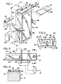
- the print head generally includes an elongated print head body 10, the length of which, L, is substantially greater than its other dimensions a and b.
- the body 10 includes an orifice plate 12 and a block of material 14.
- the body 10 defines a fluid receiving reservoir 16 in its first end, and at least one and preferably a number of orifices 18 which are arranged in a row across orifice plate 12.
- the orifice plate 12 is bonded to block 14 of material, such as stainless steel by means of a suitable adhesive.
- Block 14 defines a slot 20 which, in conjunction with orifice plate 12 defines the reservoir 16.
- the block 14 further defines a fluid supply opening 22 and a fluid outlet opening 24, both of which communicate with the slot 20.
- the fluid jet system further includes means for supplying fluid to the reservoir 16 under pressure such that fluid emerges from the orifices 18 as fluid filaments which then break up into streams of drops.
- This includes a pump 26 which receives fluid from a tank 28 and delivers it, via fluid conduit line 30, to the reservoir 16.
- a conduit 32 is connected to fluid outlet 24 such that fluid may be removed from the reservoir 16 at shut down of the print head or during cross-flushing of the reservoir 16, as described more fully below.
- the end of the print head to which conduits 30 and 32 are attached, including orifice plate 12 is subjected to mechanical vibrational energy which causes the fluid filaments to break up into streams of drops of uniform size and spacing.
- the conduits 30 and 32 are selected from among a number of materials, such as a polymeric material, which have a vibrational impedance substantially different from that of the stainless steel block 14. As a consequence, power loss through the conduits 30 and 32, and the resulting damping of the vibrations are minimized.
- the system further includes mounting flanges 34 which are relatively thin and are integrally formed with the block 14.
- the flanges 34 extend from opposite sides of the elongated print head body 10 and are substantially equidistant from the first and second ends of the body. As a result, the flanges may be used to support the body 10 in a nodal plane and are therefore not subjected to substantial stress.
- the system further comprises a transducer means, including thin piezoelectric transducers 36 and 38.
- the transducers are bonded to the exterior of the body of block 14 and extend a substantial distance along the body in the direction of elongation thereof, from adjacent the support means toward both the first and second ends of the body.
- the transducers 36 and 38 respond to a substantially electrical drive signal, provided by power supply 40 on 1'ine 42, by changing dimension, thereby causing mechanical vibration of the body and break up of the fluid streams into streams of drops.
- the piezoelectric transducers 36 and 38 have electrically conductive coatings on their outer surfaces, that is the surfaces away from the print head block 14, which define a first electrode for each such transducer.
- the metallic print head block 14 typically grounded, provides the second electrode for each of the transducers.
- the piezoelectric transducers are selected such that when driven by an a.c. drive signal, they alternately expand and contract in the direction of elongation of the print head.
- transducers 36 and 38 are electrically connected in parallel.
- the transducers are oriented such that a driving signal on line 42 causes them to elongate and contract in unison. Since the transducers 36 and 38 are bonded to the block 14, they cause the block to elongate and contract, as well.
- an additional piezoelectric transducer 44 may be bonded to one of the narrower sides of the print head to act as a feedback means and to provide an electrical feedback signal on line 46 which fluctuates in correspondence with the elongation and contraction of the print head block 14.
- the amplitude of the signal on line 46 is proportional to the amplitude of the mechanical vibration of the block 14.
- the steel block 14 which forms a part of the print head body can be considered to be a very stiff spring. If properly mechanically stimulated, it may therefore be held at its center, as by flanges 34, while both ends of the block 14 alternately move toward and away from the center. Since the center of the block lies in a' nodal plane, the flanges 34 are not subjected to substantial vibration and the support for the print head does not interfere with its operation. As the end of the print head body 10 which defines the fluid receiving reservoir 16 is vibrated, the vibrations are transmitted to the fluid filaments which emerge from the orifices 16, thus causing substantially simultaneous uniform drop break up. Note that the reservoir 16 is small in relation to the overall size of the block 14 and is centered in the end of the block. As a consequence, the reservoir 16 does not interfere significantly with the vibration of the block 14, nor affect the resonant frequency of the print head substantially.
- the block 14 is elongated and contracted without the flexure oscillations which would otherwise result if only one such piezoelectric transducer were utilized. Additionally, the use of two piezoelectric transducers allows for a higher power input into the print head for a given voltage and, consequently, for a higher maximum power input into the print head, since only a limited voltage differential may be placed across a piezoelectric transducer without break down of the transducer.
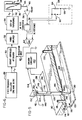
- Fig. 6 illustrates a drive means which applies a substantially sinusoidal drive signal to the transducer means and which may also be used to apply a cleaning drive signal, approximating a pulse train, to the transducer means.
- the output of a fixed frequency oscillator 48 operating at approximately 50 KHz, is supplied to transducers 36 and 38 via a voltage controlled attenuator circuit 50, a power amplifier 52 and a step-up transformer 54.
- the output from transducer 44 on line 46 is used to control the amount of attenuation provided by circuit 50.
- the signal on line 46 is amplified by amplifier 56, converted to a d.c. signal by converter 58, and then supplied to circuit 59 which, during normal operation, passes it directly to summing circuit 60.
- This signal is compared to a selected reference signal by summing circuit 60 to produce a signal on line 62 which controls the attenuation provided by circuit 50.
- summing circuit 60 By this feedback arrangement, the amplitude of the drive signal on line 42 and the amplitude of the mechanical vibration of the print head are precisely controlled.
- a substantially sinusoidal drive signal of approximately 3 volts rms is applied to the transducers.
- switch 62 When it is necessary to clean the reservoir 16, the orifice plate 12 or the orifices 18, switch 62 is actuated manually into its lower switching position in which circuit 59 attenuates the output from converter 58 by means of voltage divider formed from resistors 64 and 66. As a result of this attenuation, the summing circuit 60 supplies a control signal to attenuator 50 which causes attenuator 50 to permit a much larger amplitude signal to be applied to power amplifier 52. Amplifier 52 is driven into saturation at the extreme levels of its input, thus resulting in a square wave signal approximating a pulse train being applied to transducers 36 and 38. The square wave is of a substantially greater amplitude than the sinusoidal drive signal. Typically the cleaning drive signal fluctuates between plus and minus 9 volts.
- a square wave signal consists of a number of harmonic signals of higher frequencies.
- This cleaning drive signal therefore has at least some components which are higher in frequency than the substantially sinusoidal drive signal.
- the cleaning drive signal produces ultrasonic vibrations in the print head and associated structures which tend to dislodge dried fluid and contaminant particles from their points of attachment in the fluid supply system.
- fluid in the reservoir may be held at or below ambient pressure to insure that fluid flow through the orifices is prevented.
- the present invention may also be utilized in conjunction with a second type of print head and transducer means, as shown in Fig. 5, which operate through traveling wave stimulation in which bending waves travel along orifice plate 122.
- the print head includes a manifold means consisting of an upper manifold element 110, a lower manifold element 112, and a gasket 114 therebetween.
- the manifold means defines a fluid receiving reservoir 116 to which fluid may be applied under pressure via fluid inlet tube 118. Fluid may be removed from reservoir 116 through outlet tube 120 during cleaning operations or prior to extended periods of print head shutdown.
- An orifice plate 122 is mounted on the manifold means.
- the plate is formed of a metal material and is relatively thin so as to be somewhat flexible.
- Orifice plate 122 is bonded to the manifold element 112, as for example by solder or by an adhesive, such that it closes and defines one wall of the reservoir 116.
- Orifice plate 122 defines a plurality of orifices 124 which are arranged in at least one row and which communicate with the reservoir 116 such that fluid in the reservoir 116 flows through the orifices 124 and emerges therefrom as fluid filaments.
- the stimulator means 126 includes a stimulator member 128, configured as a thin metal rod.
- the type of metal for the stimulator member 128 is selected to be compatible with the fluid supplied to reservoir 116.
- the stimulator member 128 is of a length L which is substantially equal to nX/2, where n is a positive integer and ⁇ is the wavelength of an acoustic wave traveling along the stimulator member 128.
- the wavelength of such a wave, traveling along a thin rod is substantially equal to (Y/p) 1 / 2 /f, where Y is Young's modulus, p is the density of the stimulator member material, and f is the frequency of acoustic waves generated in the member.
- the end 130 of member 128 is tapered so that the member 128 contacts the orifice plate 122 substantially at a point. As is known, such point contact on the center line of the orifice plate 122 insures that bending waves of a first order are generated in the orifice plate 122, and that satisfactory stimulation is obtained.
- the stimulator means 126 further includes piezoelectric crystal means, comprising piezoelectric crystals 132 and 134, which are mounted on the stimulator member 128.
- the crystals 32 and 34 each include a thin, electrically conductive layer on their outer surfaces to which conductors 136 and 138 are electrically connected. The inner surfaces of the crystals are in contact with and are grounded by the member 128.
- Member 128, in turn, may be grounded through orifice plate 122 or through ground conductor 142.
- the crystals 132 and 134 are configured such that they tend to compress or extend in a direction parallel to the axis of elongation of the member 128 when a fluctuating electrical potential is placed across the crystals. As a consequence, when an a.c.
- circuit 140 supplies a substantially sinusoidal drive signal at a frequency f, as specified above in relation to the length of the member 128.
- the stimulator member is substantially equal in length to one wavelength, that is, n is equal to 2.
- the member 128 extends into the manifold means through an opening 144 defined by element 110.
- the member 128 contacts the orifice plate 122 inside the reservoir 116.
- a seal such as O-ring 146, surrounds the member 128, contacting the member 128 and element 110.
- the stimulator means is mounted by tapered pins 148 which engage generally conical detents in the sides of member 128.
- the pins 148 and detends provide a pivotal mounting which restricts movement of member 128 vertically.
- the detents are positioned 1/4 X from the upper end of the member 128, while the O-ring 146 contacts the member 128 substantially 1/4 ⁇ from the lower end of the member 128. It will be appreciated that since crystals 132 and 134 extend above and below the detents by substantially equal distances, pins 148 support the stimulator means in a nodal plane. Since the ring 146 contacts the member 128 1 / 2 A below the pins 148, O-ring 146 also contacts the memer 128 at a nodal plane.
- the end of 130 of the member 128 is 1/4a below a nodal plane and therefore at an anti-node, producing maximum amplitude mechanical stimulation for generation of the bending waves in the orifice plate 122.
- An additional pair of piezoelectric crystals 152 may also be mounted on the member 128. Crystals 152 act as a feedback means and provide an electrical feedback signal on line 154 which is proportional in frequency and amplitude to the frequency and amplitude of the acoustic waves traveling through the member 128.
- the feedback signal on line 154 may be used by the drive circuit 140 to control the amplitude of the substantially sinusoidal drive signal applied on lines 136 and 138.
- circuit 140 is identical to that shown in Fig. 6.
- circuit 140 applies a cleaning signal to transducers 132 and 134 which approximates a pulse train.
- the higher order harmonics of this non-sinusoidal driving signal cause high frequency vibrational energy to be applied to the orifice plate 122, disloding contaminant particles.
- the reservoir 116 is cross flushed by a substantial fluid flow through lines 118 and 120.
- circuit 140 once again applies a substantially sinusoidal drive signal to lines 136 and 138 and normal operation is resumed.
- the electrodes are preferably moved from their operating positions during the cleaning operation in order to avoid contamination. Alternatively, if an undesirable residue is not left on the electrodes by dried fluid, the electrodes may be left in their operating positions during print head cleaning and subsequently air dried.
Landscapes
- Particle Formation And Scattering Control In Inkjet Printers (AREA)
- Ink Jet (AREA)
Applications Claiming Priority (2)
| Application Number | Priority Date | Filing Date | Title |
|---|---|---|---|
| US06/495,183 US4563688A (en) | 1983-05-16 | 1983-05-16 | Fluid jet printer and method of ultrasonic cleaning |
| US495183 | 1990-03-19 |
Publications (3)
| Publication Number | Publication Date |
|---|---|
| EP0126536A2 true EP0126536A2 (de) | 1984-11-28 |
| EP0126536A3 EP0126536A3 (en) | 1985-05-29 |
| EP0126536B1 EP0126536B1 (de) | 1987-10-14 |
Family
ID=23967607
Family Applications (1)
| Application Number | Title | Priority Date | Filing Date |
|---|---|---|---|
| EP84302318A Expired EP0126536B1 (de) | 1983-05-16 | 1984-04-04 | Flüssigkeitsstrahldrucker und sein mit Ultraschall betriebenes Reinigungsverfahren |
Country Status (5)
| Country | Link |
|---|---|
| US (1) | US4563688A (de) |
| EP (1) | EP0126536B1 (de) |
| JP (1) | JPS59212273A (de) |
| CA (1) | CA1220667A (de) |
| DE (1) | DE3466769D1 (de) |
Cited By (6)
| Publication number | Priority date | Publication date | Assignee | Title |
|---|---|---|---|---|
| WO1986006025A1 (en) * | 1985-04-12 | 1986-10-23 | Eastman Kodak Company | Ink jet printing apparatus having ultrasonic print head cleaning system |
| EP0259193A1 (de) * | 1986-09-05 | 1988-03-09 | Ing. C. Olivetti & C., S.p.A. | Gerät zur Instandsetzung von Tintenstrahldruckdüsen |
| EP0624468A3 (de) * | 1993-05-12 | 1995-06-21 | Scitex Digital Printing Inc | Überwachung der Tintenstrahlanregung. |
| WO1997026996A3 (de) * | 1996-01-23 | 1997-10-23 | Koenig & Bauer Albert Ag | Verfahren und einrichtung zum sauberhalten von düsenmundstücken eines sprühfeuchtwerkes einer rotationsdruckmaschine |
| CN101457537B (zh) * | 2008-12-26 | 2011-05-04 | 太原重工股份有限公司 | 大型矿用挖掘机交流变频调速装置及其控制系统 |
| CN107097533A (zh) * | 2017-06-01 | 2017-08-29 | 佛山石湾鹰牌陶瓷有限公司 | 一种喷墨机墨水的布均摆动机 |
Families Citing this family (20)
| Publication number | Priority date | Publication date | Assignee | Title |
|---|---|---|---|---|
| US4797687A (en) * | 1985-05-01 | 1989-01-10 | Burlington Industries, Inc. | Patterning effects with fluid jet applicator |
| US4849768A (en) * | 1985-05-01 | 1989-07-18 | Burlington Industries, Inc. | Printing random patterns with fluid jets |
| US4683477A (en) * | 1986-08-29 | 1987-07-28 | Eastman Kodak Company | Ink jet print head |
| EP0292779A1 (de) * | 1987-05-25 | 1988-11-30 | Siemens Aktiengesellschaft | Verfahren und Vorrichtung zur Reinigung von Bauteilen mit Hohlräumen |
| US4849769A (en) * | 1987-06-02 | 1989-07-18 | Burlington Industries, Inc. | System for ultrasonic cleaning of ink jet orifices |
| US4973980A (en) * | 1987-09-11 | 1990-11-27 | Dataproducts Corporation | Acoustic microstreaming in an ink jet apparatus |
| JP2832443B2 (ja) * | 1988-11-22 | 1998-12-09 | 本多電子株式会社 | マルチ周波数超音波洗浄方法及び洗浄装置 |
| US5394179A (en) * | 1992-03-20 | 1995-02-28 | Scitex Digital Printing, Inc. | Stimulator for continous ink print head |
| US5757396A (en) * | 1994-06-30 | 1998-05-26 | Compaq Computer Corporation | Ink jet printhead having an ultrasonic maintenance system incorporated therein and an associated method of maintaining an ink jet printhead by purging foreign matter therefrom |
| EP0911171A1 (de) * | 1997-10-22 | 1999-04-28 | Hewlett-Packard Company | Reinigen von Druckerdüsen unter Verwendung von Vibrationen |
| HUP9800508A1 (hu) * | 1998-03-09 | 2000-02-28 | György Hegedűs | Szerkezet vibrációs folyadékadagoláshoz |
| US6267464B1 (en) | 1998-12-28 | 2001-07-31 | Eastman Kodak Company | Self cleaning ink jet printhead cartridges |
| US6168256B1 (en) * | 1998-12-29 | 2001-01-02 | Eastman Kodak Company | Self-cleaning ink jet printer with oscillating septum and method of assembling the printer |
| DE60031065T2 (de) | 1999-10-29 | 2007-05-16 | Eastman Kodak Co. | Verbessertes Ultraschallreinigungssystem für Tintenstrahldrucksysteme |
| US7128410B2 (en) * | 2004-03-17 | 2006-10-31 | Videojet Technologies Inc. | Ink jet print head cleaning system |
| US7150512B2 (en) * | 2004-03-17 | 2006-12-19 | Videojet Technologies Inc. | Cleaning system for a continuous ink jet printer |
| US7178897B2 (en) * | 2004-09-15 | 2007-02-20 | Eastman Kodak Company | Method for removing liquid in the gap of a printhead |
| WO2012150958A1 (en) * | 2011-05-02 | 2012-11-08 | Enertechnix, Inc | Aerosol collection apparatus and methods for ultrasonic care thereof |
| US9884406B2 (en) | 2014-01-15 | 2018-02-06 | Flow International Corporation | High-pressure waterjet cutting head systems, components and related methods |
| US10596717B2 (en) | 2015-07-13 | 2020-03-24 | Flow International Corporation | Methods of cutting fiber reinforced polymer composite workpieces with a pure waterjet |
Family Cites Families (22)
| Publication number | Priority date | Publication date | Assignee | Title |
|---|---|---|---|---|
| US2514080A (en) * | 1945-01-10 | 1950-07-04 | Bell Telephone Labor Inc | Method of obtaining high velocity with crystals |
| US3131515A (en) * | 1960-01-04 | 1964-05-05 | Bell Telephone Labor Inc | Methods and apparatus employing torsionally vibratory energy |
| US3661304A (en) * | 1970-08-03 | 1972-05-09 | Mead Corp | Pressure impulse apparatus for initiating formation of fluid drops |
| US3701998A (en) * | 1971-10-14 | 1972-10-31 | Mead Corp | Twin row drop generator |
| JPS5129769A (ja) * | 1974-09-05 | 1976-03-13 | Oishi Seisaku | Chikusanfunnyokongosuisenosui no koekibunrisoniokeru chindenodeihaishutsusochi |
| US4007465A (en) * | 1975-11-17 | 1977-02-08 | International Business Machines Corporation | System for self-cleaning ink jet head |
| JPS5932313B2 (ja) * | 1976-06-07 | 1984-08-08 | コニカ株式会社 | インクジエツト記録装置のインク通路洗浄方法 |
| JPS52150029A (en) * | 1976-06-07 | 1977-12-13 | Konishiroku Photo Ind Co Ltd | Ink jet recording device |
| JPS5835304B2 (ja) * | 1977-09-14 | 1983-08-02 | オムロン株式会社 | 複数台の電子式キャッシュレジスタの制御方式 |
| JPS5448551A (en) * | 1977-09-26 | 1979-04-17 | Ricoh Co Ltd | Ink jet driving circuit |
| US4223322A (en) * | 1977-12-08 | 1980-09-16 | Olympia Werke Ag | Maintaining the nozzle surface of an ink writing head |
| JPS592617B2 (ja) * | 1977-12-22 | 1984-01-19 | 株式会社リコー | インク噴射装置 |
| US4306245A (en) * | 1978-09-21 | 1981-12-15 | Canon Kabushiki Kaisha | Liquid jet device with cleaning protective means |
| US4240081A (en) * | 1978-10-13 | 1980-12-16 | Dennison Manufacturing Company | Ink jet printing |
| JPS55100167A (en) * | 1979-01-24 | 1980-07-30 | Canon Inc | Ink jet mechanism |
| JPS55150373A (en) * | 1979-05-14 | 1980-11-22 | Ricoh Co Ltd | Bubble remover for ink jet printer |
| JPS55158974A (en) * | 1979-05-26 | 1980-12-10 | Ricoh Co Ltd | Choking detector in ink jet printer and remover thereof |
| US4257052A (en) * | 1979-10-29 | 1981-03-17 | The Mead Corporation | Molded orifice plate assembly for an ink jet recorder and method of manufacture |
| US4323908A (en) * | 1980-08-01 | 1982-04-06 | International Business Machines Corp. | Resonant purging of drop-on-demand ink jet print heads |
| US4326553A (en) * | 1980-08-28 | 1982-04-27 | Rca Corporation | Megasonic jet cleaner apparatus |
| JPS5818273A (ja) * | 1981-07-27 | 1983-02-02 | Sharp Corp | インク噴射ノズル内の空気除去方法 |
| US4340897A (en) * | 1981-07-29 | 1982-07-20 | Pitney Bowes Inc. | Cleaning device for writing heads used in ink jet recorders and printers |
-
1983
- 1983-05-16 US US06/495,183 patent/US4563688A/en not_active Expired - Lifetime
-
1984
- 1984-04-04 DE DE8484302318T patent/DE3466769D1/de not_active Expired
- 1984-04-04 EP EP84302318A patent/EP0126536B1/de not_active Expired
- 1984-05-09 CA CA000453897A patent/CA1220667A/en not_active Expired
- 1984-05-11 JP JP59094408A patent/JPS59212273A/ja active Pending
Cited By (8)
| Publication number | Priority date | Publication date | Assignee | Title |
|---|---|---|---|---|
| WO1986006025A1 (en) * | 1985-04-12 | 1986-10-23 | Eastman Kodak Company | Ink jet printing apparatus having ultrasonic print head cleaning system |
| EP0259193A1 (de) * | 1986-09-05 | 1988-03-09 | Ing. C. Olivetti & C., S.p.A. | Gerät zur Instandsetzung von Tintenstrahldruckdüsen |
| EP0624468A3 (de) * | 1993-05-12 | 1995-06-21 | Scitex Digital Printing Inc | Überwachung der Tintenstrahlanregung. |
| WO1997026996A3 (de) * | 1996-01-23 | 1997-10-23 | Koenig & Bauer Albert Ag | Verfahren und einrichtung zum sauberhalten von düsenmundstücken eines sprühfeuchtwerkes einer rotationsdruckmaschine |
| US6067908A (en) * | 1996-01-23 | 2000-05-30 | Koenig & Bauer-Albert Aktiengesellschaft | Method and device for keeping clean ends of spray damping mechanism nozzles on rotary printing press |
| CN101457537B (zh) * | 2008-12-26 | 2011-05-04 | 太原重工股份有限公司 | 大型矿用挖掘机交流变频调速装置及其控制系统 |
| CN107097533A (zh) * | 2017-06-01 | 2017-08-29 | 佛山石湾鹰牌陶瓷有限公司 | 一种喷墨机墨水的布均摆动机 |
| CN107097533B (zh) * | 2017-06-01 | 2019-06-21 | 佛山石湾鹰牌陶瓷有限公司 | 一种喷墨机墨水的布均摆动机 |
Also Published As
| Publication number | Publication date |
|---|---|
| JPS59212273A (ja) | 1984-12-01 |
| EP0126536B1 (de) | 1987-10-14 |
| US4563688A (en) | 1986-01-07 |
| DE3466769D1 (en) | 1987-11-19 |
| CA1220667A (en) | 1987-04-21 |
| EP0126536A3 (en) | 1985-05-29 |
Similar Documents
| Publication | Publication Date | Title |
|---|---|---|
| EP0126536B1 (de) | Flüssigkeitsstrahldrucker und sein mit Ultraschall betriebenes Reinigungsverfahren | |
| EP0218686B1 (de) | Tintenstrahlschreiber versehen mit einem mit ultraschall betriebenen reinigungsverfahren des druckkopfes | |
| US3739393A (en) | Apparatus and method for generation of drops using bending waves | |
| US4849769A (en) | System for ultrasonic cleaning of ink jet orifices | |
| EP0216912B1 (de) | Reinigungsverfahren für tintenstrahldruckkopf | |
| JPH0452217B2 (de) | ||
| JPS5842830B2 (ja) | 複数の液体小滴流を生成する装置 | |
| US4250510A (en) | Fluid jet device | |
| US3701476A (en) | Drop generator with rotatable transducer | |
| US8523327B2 (en) | Printhead including port after filter | |
| US3882508A (en) | Stimulation apparatus for a jet drop recorder | |
| US20110205306A1 (en) | Reinforced membrane filter for printhead | |
| US4188635A (en) | Ink jet printing head | |
| US4031563A (en) | Jet drop recording head having an improved porous deflection ribbon | |
| US4286272A (en) | Ink jet printer and start up method therefor | |
| US4554558A (en) | Fluid jet print head | |
| US4473830A (en) | Ink jet print head | |
| US20190030898A1 (en) | Jetting-module cleaning system with rotating wiper mechanism | |
| EP0097413B1 (de) | Flüssigkeitsdruckkopf und Methode, das Aufreissen eines aus ihm fliessenden Fluidstromes anzuregen | |
| US3787883A (en) | Deflection electrode assembly for a jet drop recorder | |
| EP0126649B1 (de) | Flüssigkeitsstrahldruckkopf | |
| WO1986005985A1 (en) | Method for counteracting the effects of sodium chloride | |
| US6505920B1 (en) | Synchronously stimulated continuous ink jet head | |
| USRE35737E (en) | Accoustically soft ink jet nozzle assembly | |
| JP2002144557A (ja) | インクジェットヘッドの駆動方法 |
Legal Events
| Date | Code | Title | Description |
|---|---|---|---|
| PUAI | Public reference made under article 153(3) epc to a published international application that has entered the european phase |
Free format text: ORIGINAL CODE: 0009012 |
|
| AK | Designated contracting states |
Designated state(s): BE CH DE FR GB IT LI NL SE |
|
| PUAL | Search report despatched |
Free format text: ORIGINAL CODE: 0009013 |
|
| AK | Designated contracting states |
Designated state(s): BE CH DE FR GB IT LI NL SE |
|
| 17P | Request for examination filed |
Effective date: 19851121 |
|
| 17Q | First examination report despatched |
Effective date: 19870219 |
|
| GRAA | (expected) grant |
Free format text: ORIGINAL CODE: 0009210 |
|
| AK | Designated contracting states |
Kind code of ref document: B1 Designated state(s): BE CH DE FR GB IT LI NL SE |
|
| REF | Corresponds to: |
Ref document number: 3466769 Country of ref document: DE Date of ref document: 19871119 |
|
| ITF | It: translation for a ep patent filed | ||
| ET | Fr: translation filed | ||
| PLBE | No opposition filed within time limit |
Free format text: ORIGINAL CODE: 0009261 |
|
| STAA | Information on the status of an ep patent application or granted ep patent |
Free format text: STATUS: NO OPPOSITION FILED WITHIN TIME LIMIT |
|
| 26N | No opposition filed | ||
| PGFP | Annual fee paid to national office [announced via postgrant information from national office to epo] |
Ref country code: CH Payment date: 19890313 Year of fee payment: 6 |
|
| PGFP | Annual fee paid to national office [announced via postgrant information from national office to epo] |
Ref country code: SE Payment date: 19890315 Year of fee payment: 6 |
|
| PGFP | Annual fee paid to national office [announced via postgrant information from national office to epo] |
Ref country code: BE Payment date: 19890328 Year of fee payment: 6 |
|
| ITTA | It: last paid annual fee | ||
| PGFP | Annual fee paid to national office [announced via postgrant information from national office to epo] |
Ref country code: NL Payment date: 19890430 Year of fee payment: 6 |
|
| PG25 | Lapsed in a contracting state [announced via postgrant information from national office to epo] |
Ref country code: SE Effective date: 19900405 |
|
| PG25 | Lapsed in a contracting state [announced via postgrant information from national office to epo] |
Ref country code: LI Effective date: 19900430 Ref country code: CH Effective date: 19900430 Ref country code: BE Effective date: 19900430 |
|
| BERE | Be: lapsed |
Owner name: EASTMAN KODAK CY Effective date: 19900430 |
|
| PG25 | Lapsed in a contracting state [announced via postgrant information from national office to epo] |
Ref country code: NL Effective date: 19901101 |
|
| NLV4 | Nl: lapsed or anulled due to non-payment of the annual fee | ||
| REG | Reference to a national code |
Ref country code: CH Ref legal event code: PL |
|
| REG | Reference to a national code |
Ref country code: FR Ref legal event code: TP |
|
| EUG | Se: european patent has lapsed |
Ref document number: 84302318.5 Effective date: 19910115 |
|
| REG | Reference to a national code |
Ref country code: GB Ref legal event code: IF02 |
|
| PGFP | Annual fee paid to national office [announced via postgrant information from national office to epo] |
Ref country code: GB Payment date: 20030326 Year of fee payment: 20 |
|
| PGFP | Annual fee paid to national office [announced via postgrant information from national office to epo] |
Ref country code: DE Payment date: 20030331 Year of fee payment: 20 |
|
| PGFP | Annual fee paid to national office [announced via postgrant information from national office to epo] |
Ref country code: FR Payment date: 20030408 Year of fee payment: 20 |
|
| PG25 | Lapsed in a contracting state [announced via postgrant information from national office to epo] |
Ref country code: GB Free format text: LAPSE BECAUSE OF EXPIRATION OF PROTECTION Effective date: 20040403 |
|
| REG | Reference to a national code |
Ref country code: GB Ref legal event code: 732E |
|
| REG | Reference to a national code |
Ref country code: GB Ref legal event code: PE20 |
|
| REG | Reference to a national code |
Ref country code: FR Ref legal event code: TP |