EP0126446A2 - Noise filter and production method - Google Patents
Noise filter and production method Download PDFInfo
- Publication number
- EP0126446A2 EP0126446A2 EP84105637A EP84105637A EP0126446A2 EP 0126446 A2 EP0126446 A2 EP 0126446A2 EP 84105637 A EP84105637 A EP 84105637A EP 84105637 A EP84105637 A EP 84105637A EP 0126446 A2 EP0126446 A2 EP 0126446A2
- Authority
- EP
- European Patent Office
- Prior art keywords
- noise filter
- conductive
- foil
- electromagnetically
- noise
- Prior art date
- Legal status (The legal status is an assumption and is not a legal conclusion. Google has not performed a legal analysis and makes no representation as to the accuracy of the status listed.)
- Granted
Links
- 238000004519 manufacturing process Methods 0.000 title claims abstract description 11
- 239000011888 foil Substances 0.000 claims abstract description 29
- XEEYBQQBJWHFJM-UHFFFAOYSA-N Iron Chemical compound [Fe] XEEYBQQBJWHFJM-UHFFFAOYSA-N 0.000 claims abstract description 23
- 239000000463 material Substances 0.000 claims description 7
- 238000004804 winding Methods 0.000 claims description 7
- 239000011248 coating agent Substances 0.000 claims description 4
- 238000000576 coating method Methods 0.000 claims description 4
- 239000004020 conductor Substances 0.000 claims description 4
- 238000003475 lamination Methods 0.000 claims description 3
- WABPQHHGFIMREM-UHFFFAOYSA-N lead(0) Chemical compound [Pb] WABPQHHGFIMREM-UHFFFAOYSA-N 0.000 claims description 3
- 238000003825 pressing Methods 0.000 claims description 2
- 230000001681 protective effect Effects 0.000 claims description 2
- 238000010030 laminating Methods 0.000 claims 1
- 239000003990 capacitor Substances 0.000 abstract description 7
- 229910052742 iron Inorganic materials 0.000 description 9
- 229910052782 aluminium Inorganic materials 0.000 description 7
- XAGFODPZIPBFFR-UHFFFAOYSA-N aluminium Chemical compound [Al] XAGFODPZIPBFFR-UHFFFAOYSA-N 0.000 description 7
- 230000001629 suppression Effects 0.000 description 7
- 238000000034 method Methods 0.000 description 6
- 229910052751 metal Inorganic materials 0.000 description 5
- 239000002184 metal Substances 0.000 description 5
- 229920002799 BoPET Polymers 0.000 description 4
- 230000008901 benefit Effects 0.000 description 3
- 230000001939 inductive effect Effects 0.000 description 3
- 238000009413 insulation Methods 0.000 description 3
- 239000011324 bead Substances 0.000 description 2
- 230000000694 effects Effects 0.000 description 2
- RYGMFSIKBFXOCR-UHFFFAOYSA-N Copper Chemical compound [Cu] RYGMFSIKBFXOCR-UHFFFAOYSA-N 0.000 description 1
- 239000005041 Mylar™ Substances 0.000 description 1
- 229910052802 copper Inorganic materials 0.000 description 1
- 239000010949 copper Substances 0.000 description 1
- 230000008878 coupling Effects 0.000 description 1
- 238000010168 coupling process Methods 0.000 description 1
- 238000005859 coupling reaction Methods 0.000 description 1
- 239000000428 dust Substances 0.000 description 1
- 230000004907 flux Effects 0.000 description 1
- 238000009499 grossing Methods 0.000 description 1
- 238000010438 heat treatment Methods 0.000 description 1
- 230000006872 improvement Effects 0.000 description 1
- 239000006247 magnetic powder Substances 0.000 description 1
- 238000012986 modification Methods 0.000 description 1
- 230000004048 modification Effects 0.000 description 1
- 229910000595 mu-metal Inorganic materials 0.000 description 1
- 238000007747 plating Methods 0.000 description 1
- 230000008569 process Effects 0.000 description 1
- 125000006850 spacer group Chemical group 0.000 description 1
- 238000004544 sputter deposition Methods 0.000 description 1
- 238000007740 vapor deposition Methods 0.000 description 1
- 229910000859 α-Fe Inorganic materials 0.000 description 1
Images


Classifications
-
- H—ELECTRICITY
- H03—ELECTRONIC CIRCUITRY
- H03H—IMPEDANCE NETWORKS, e.g. RESONANT CIRCUITS; RESONATORS
- H03H1/00—Constructional details of impedance networks whose electrical mode of operation is not specified or applicable to more than one type of network
-
- C—CHEMISTRY; METALLURGY
- C21—METALLURGY OF IRON
- C21B—MANUFACTURE OF IRON OR STEEL
- C21B7/00—Blast furnaces
- C21B7/04—Blast furnaces with special refractories
- C21B7/06—Linings for furnaces
-
- Y—GENERAL TAGGING OF NEW TECHNOLOGICAL DEVELOPMENTS; GENERAL TAGGING OF CROSS-SECTIONAL TECHNOLOGIES SPANNING OVER SEVERAL SECTIONS OF THE IPC; TECHNICAL SUBJECTS COVERED BY FORMER USPC CROSS-REFERENCE ART COLLECTIONS [XRACs] AND DIGESTS
- Y10—TECHNICAL SUBJECTS COVERED BY FORMER USPC
- Y10T—TECHNICAL SUBJECTS COVERED BY FORMER US CLASSIFICATION
- Y10T29/00—Metal working
- Y10T29/49—Method of mechanical manufacture
- Y10T29/49002—Electrical device making
- Y10T29/4902—Electromagnet, transformer or inductor
Definitions
- This invention generally pertains to a noise filter and to a method of its production, and more specifically to a filter particularly suited for suppressing noise and ripple components in power supply and smoothing circuits.
- Noise filters are generally used for preventing mulfunc- tions of electronic equipment by noise transmitted thereto and superimposed with its power supply and for suppressing any noise generated in an equipment and transmitted to any other equipment or power supply.
- noise filters comprising inductance (L) connected in series with a power supply and shunt capacitance (C) as shown in Fig. 1 have been widely used for the above purposes.
- the inductance L for use in such noise filter circuit takes various forms including a coil 2 wound around a magnetic core 1 such as a toroidal type ferrite core or a dust core as shown in Fig. 2a or a conductive wire 5 passing through openings 3 in a bead magnetic core 4 as shown in Fig. 2b.
- a magnetic core 1 such as a toroidal type ferrite core or a dust core as shown in Fig. 2a or a conductive wire 5 passing through openings 3 in a bead magnetic core 4 as shown in Fig. 2b.
- a primary problem associated with the manufacturing of such noise filters is high production cost of the inductance L, especially pressing and heating processes of the magnetic core and winding of the coil in addition to connecting of the capacitor C.
- Japanese laid open patent application (Kokai) No. 9764/77 shows a power supply noise filter made of a metal foil wound in a spiral manner with a pair of lead wires connected at both ends to form the inductance L. Additionally, another metal foil is laminated with the first mentioned metal foil with an insulting separator therebetween to form a shunt capacitance.
- Japanese utility model publication No. 24900/80 an improvement of such metal foil spiral inductance is described by adding external inductors to provide a bypass for the DC component.
- Japanese laid open patent application (Kokai) No. 21810/82 discloses a technique to increase the spiral inductance by coating magnetic powder on one or both surfaces of the insulating film.
- this technique requires an additional process and is more expensive than the above mentioned prior art approach.
- Noise filters according to the present invention provide for a larger inductance with a given size of the conductive foil by using an electromagnetically conductive film or foil as at least one of the metal films to be wound in a spiral manner with insulating separators.
- the electromagnetically conductive film in this specification means any thin material of good conductivity to electric-current and magnetic flux.
- the electrically conductive film is placed so close to the electrically or electromagnetically conductive film over the entire length that the inductance of the spirally wound conductor is significantly increased in comparison to the prior art devices, thereby providing a required inductance without using a magnetic core or winding an undesirably long film while forming a capacitance distributed over the entire length.
- a good electrically conductive band 6 is made of copper or aluminum foil and includes lead wires 7 and 8 connected near to both ends of the band 6.
- Another electromagnetically conductive band 9 made of a thin sheet of iron or a similar material includes a lead wire 10 connected thereto and which conductive band 9 is disposed in superimposed relation with the electrically conductive band 6 with an insulation band 11 such as an insulation sheet or a capacitor paper between both bands 6 and 9.
- a stable iron sheet or film of uniform thickness is now available under terms like "galvanized electro-deposited iron foil". It should be noted, however, that the electrically conductive film may be other than iron as long as it exhibits excellent magnetic and electric conductivity.
- the whole sandwich arrangement is integrally wound in a tubular form as shown in Fig. 4, thereby providing a noise filter 12 with a capacitance distributed over the entire length of the coil.
- the entire noise filter may be pressed to an oval cross section before coating with a protective material.
- the noise filter 12 thus formed comprises a coil of an electrically conductive band 6 between a pair of lead wires 7 and 8 and a capacitance distributed between the electrically conductive band 6 and the electromagnetically conductive band 9 over the entire length of the band 6.
- the electromagnetically conductive band 9 is sandwitched between electrically conductive band 6 with insulation spacer to increase the inductance of the coil.
- the conductive bands 6 and 9 may be provided directly on the respective insulating film by vapor deposition, non-electrolitic plating, sputtering or similar technique, thereby miniaturing the noise filter. Additionally the inductive coupling between both bands 6 and 9 aids to provide better noise suppression. Larger inductance values will result if the width t of band 6 is choosen to be smaller than the width t' of band 9, thereby effectively burrying band 6 when wound to a tubular form.
- Another embodiment of this invention uses electromagnetically conductive bands such as iron films for both bands 6 and 9 in Fig. 3.
- This embodiment is essentially the same as the first embodiment except for the material of the film or band 6.
- electrical performance of the second embodiment has been found to be superior to the first embodiment or prior art noise filters.
- noise suppression characteristic curve or frequency attenuation ratio characteristic curve of the noise filters according to this invention will be described hereunder in comparison with corresponding curves of conventional noise filters.
- Fig. 5 shows four attenuation characteristic curves (in dB) against frequency of various noise filters in accordance with the test scheme of Japanese Industrial Standard (JIS-c6904-1977) for suppression effect test circuits applied for symmetrical noise signal voltages developed over a 50 ⁇ non-inductive (net equivalent) termination resistor connected to the output.
- the dotted line characteristic curve A represents the measuring values of a conventional noise filter as commercially available from TDK Corporation as product type ZBF253D-01 and comprising a series inductance L made of a bead core and a shunt Mylar capacitor C of approximately 0.01 uF connected as shown in Fig. 1.
- the known tested filter device had the dimensions of 4.8 mm in night and 6 mm for the long and 3 mm for the short diameters, respectively.
- the dotted line characteristic cuver B represents the measuring result of a prior art noise filter B comprising a good electrically conductive aluminum band of 12 mm width and about 55 ⁇ m thickness wound with sixteen turns to obtain essentially the same capacitance ( ⁇ 0.01 ⁇ F) as that of the above sample A.
- the characteristic curve C Represented by the characteristic curve C is the measuring result of a first embodiment of the noise filter according to this invention using an aluminum foil of 12 mm width and about 55 ⁇ m thickness as electrically conductive band 6 and an iron foil of 12 mm width and about 20 ⁇ m thickness as electromagnetically conductive band 9 both wound with seventeen turns with an appropriate insulating separator to obtain essentially the same capacitance ( ⁇ 0.01 ⁇ F) as with the sample A.
- the measuring result of another embodiment of the noise filter according to this invention is plotted using 12 mm wide and about 20 ⁇ m thick iron foils as both electromagnetically conductive bands 6 and 9 wound with seventeen turns and an appropriate insulating separator to obtain a capacitance about 0.01 ⁇ F.
- a pair of non-magnetic, electrically conductive bands with 12 mm width and 20 ⁇ m of thickness were wound to a tubular form with a pair of 15 mm wide and 57 ⁇ m thick Mylar tapes leaving an air core of 4 mm in diameter.
- B-1, B-2 and B-3 a pair of 50 cm, 100 cm and 150 cm long aluminum foils were used and wound with 17, 28 and 38 turns, respectively.
- a 12 mm wide, 20 ⁇ m thick aluminum foil and iron foil of the same size were used as electrically conductive and electromagnetically conductive bands. Both bands were wound in a tubular form with a pair of 15 mm wide, 57 ⁇ m thick Mylar tapes therebetween leaving an air core of 4 mm in diameter.
- Three samples C-l, C-2 and C-3 use 50 cm, 100 cm and 150 cm long aluminum and iron foils were used and wound with 17, 28 and 38 turns, respectively.
- a pair of 12 mm wide, 20 ⁇ m thick iron foils were used as electromagnetically conductive foils 6 and 9 and were wound to a tubular form with a pair of 15 mm wide, 57 ⁇ m thick Mylar tapes therebetween leaving an air core of 4 mm in diameter.
- Three samples D-1, D-2 and D-3 use 50 cm, 100 cm and 150 cm long iron foils were used and wound with 17, 28 and 38 turns, respectively.
- the samples had essentially the same number of turns of the windings and same size. Therefore, the differences in electrical performance are mainly responsible for the differences in materials of the conductive bands 6 and 9.
- the two embodiments according to this invention are generally superior in noise suppression properties over a wide frequency range. Especially, the sample D is better than any other samples.
- Figs. 9 and 10 each show characteristic curves of three samples C-1, C-2 and C-3 and D-1, D-2 and D-3 to demonstrate the effect of noise suppression due to different turns of the windings. It can be said that the noise filter performance is improved over a wide frequency range as the number of turns increases. The difference is significant at low frequencies. That is, the attenuation factor increases at low frequencies with large turns of the windings. Also shown in Figs. 9 and 10 are the characteristic curves of the conventional sample A to demonstrate the advantage of the present invention over the prior art noise filter composed of discrete elements.
- the present invention modifies the conventional tubular capacitors in respect to the material of the conductive foil, thereby providing samples, compact, and less expensive noise filters with excellent noise suppression characteristic over wide frequency ranges.
- the noise filter can be made in large quantity by using conventional production facility with essentially no additional technique.
- the width of the conductive bands and the thickness of the insulating separators can be choosen depending on the current flowing through the coil and the applied voltage.
- the electromagnetically conductive film may be amorphous iron or MU-metal, or a lamination of electrically conductive and magnetically conductive layers.
- the noise filters find wide appreciations and a plurality of filters can be connected in cascade manner to provide higher noise attenuation. Such a multiple noise filter arrangement may be integrated in a single device. Therefore, such changes and modifications are deemed to be covered by the scope of the present invention.
Abstract
Description
- This invention generally pertains to a noise filter and to a method of its production, and more specifically to a filter particularly suited for suppressing noise and ripple components in power supply and smoothing circuits.
- Noise filters are generally used for preventing mulfunc- tions of electronic equipment by noise transmitted thereto and superimposed with its power supply and for suppressing any noise generated in an equipment and transmitted to any other equipment or power supply.
- Hitherto, noise filters comprising inductance (L) connected in series with a power supply and shunt capacitance (C) as shown in Fig. 1 have been widely used for the above purposes.
- The inductance L for use in such noise filter circuit takes various forms including a
coil 2 wound around amagnetic core 1 such as a toroidal type ferrite core or a dust core as shown in Fig. 2a or aconductive wire 5 passing throughopenings 3 in a bead magnetic core 4 as shown in Fig. 2b. - A primary problem associated with the manufacturing of such noise filters is high production cost of the inductance L, especially pressing and heating processes of the magnetic core and winding of the coil in addition to connecting of the capacitor C.
- Many attempts have been made to solve the problems and to provide less expensive noise filters. One effective approach is to integrate both inductive and capacitive elements into a single device and also to eliminate the need for the magnetic core. Japanese laid open patent application (Kokai) No. 9764/77 shows a power supply noise filter made of a metal foil wound in a spiral manner with a pair of lead wires connected at both ends to form the inductance L. Additionally, another metal foil is laminated with the first mentioned metal foil with an insulting separator therebetween to form a shunt capacitance. In Japanese utility model publication No. 24900/80 an improvement of such metal foil spiral inductance is described by adding external inductors to provide a bypass for the DC component. With these prior art measures, some of the problems associated with the conventional noise filters comprising discrete inductance and capacitance elements can be solved. However, the prior art integrated noise filters are not satisfactory because of a relatively low inductance.
- Japanese laid open patent application (Kokai) No. 21810/82 discloses a technique to increase the spiral inductance by coating magnetic powder on one or both surfaces of the insulating film. However, this technique requires an additional process and is more expensive than the above mentioned prior art approach.
- Noise filters according to the present invention provide for a larger inductance with a given size of the conductive foil by using an electromagnetically conductive film or foil as at least one of the metal films to be wound in a spiral manner with insulating separators. The electromagnetically conductive film in this specification means any thin material of good conductivity to electric-current and magnetic flux. The electrically conductive film is placed so close to the electrically or electromagnetically conductive film over the entire length that the inductance of the spirally wound conductor is significantly increased in comparison to the prior art devices, thereby providing a required inductance without using a magnetic core or winding an undesirably long film while forming a capacitance distributed over the entire length.
- It is therefore the primary object of this invention to provide a compact noise filter comprising series inductance and shunt capacitance integrated into a generally tubular form without using a magnetic core.
- It is another object of this invention to provide a noise filter that can be fabricated essentially the same manner and the same production facility as a tubular capacitor.
- It is yet another object of this invention to provide a noise filter with excellent noise suppression characteristic over a wide frequency range.
- It is still another object of this invention to provide a noise filter requiring less number of turns for the winding of the inductor.
- It is an additional object of this invention to provide a noise filter simpler and less expensive to manufacture.
- These and other objects of this invention along with its operation and advantages will best understood from reading the following description of preferred embodiments of this invention by reference to the accompanying drawings.
-
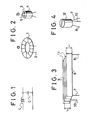
- Fig. 1 is a basic circuit of a conventional noise filter comprising discrete inductor and capacitor elements;
- Fig. 2a and b are two typical prior art inductors to be used in the conventional noise filter of Fig. 1;
- Fig. 3 is an expanded view of one embodiment of the invention;
- Fig. 4 is a perspective view of one embodiment of a tubular noise filter according to the invention;
- Figs. 5 through 8 are attenuation characteristic curves of different samples of two embodiments of the noise filter according to the invention in comparison to conventional noise filters;
- Figs. 9 and 10 are attenuation characteristic curves of various samples to show how inductance and capacitance effect the overall characteristics.
- Referring now to Fig. 3 illustrating an expanded view of the noise filter according to this invention, a good electrically conductive band 6 is made of copper or aluminum foil and includes
lead wires 7 and 8 connected near to both ends of the band 6. Another electromagnetically conductive band 9 made of a thin sheet of iron or a similar material includes alead wire 10 connected thereto and which conductive band 9 is disposed in superimposed relation with the electrically conductive band 6 with an insulation band 11 such as an insulation sheet or a capacitor paper between both bands 6 and 9. A stable iron sheet or film of uniform thickness is now available under terms like "galvanized electro-deposited iron foil". It should be noted, however, that the electrically conductive film may be other than iron as long as it exhibits excellent magnetic and electric conductivity. The whole sandwich arrangement is integrally wound in a tubular form as shown in Fig. 4, thereby providing anoise filter 12 with a capacitance distributed over the entire length of the coil. The entire noise filter may be pressed to an oval cross section before coating with a protective material. - The
noise filter 12 thus formed comprises a coil of an electrically conductive band 6 between a pair oflead wires 7 and 8 and a capacitance distributed between the electrically conductive band 6 and the electromagnetically conductive band 9 over the entire length of the band 6. It should be noted that the electromagnetically conductive band 9 is sandwitched between electrically conductive band 6 with insulation spacer to increase the inductance of the coil. The conductive bands 6 and 9 may be provided directly on the respective insulating film by vapor deposition, non-electrolitic plating, sputtering or similar technique, thereby miniaturing the noise filter. Additionally the inductive coupling between both bands 6 and 9 aids to provide better noise suppression. Larger inductance values will result if the width t of band 6 is choosen to be smaller than the width t' of band 9, thereby effectively burrying band 6 when wound to a tubular form. - Another embodiment of this invention uses electromagnetically conductive bands such as iron films for both bands 6 and 9 in Fig. 3. This embodiment is essentially the same as the first embodiment except for the material of the film or band 6. As is understood from the description hereinafter, however, electrical performance of the second embodiment has been found to be superior to the first embodiment or prior art noise filters.
- Now, noise suppression characteristic curve or frequency attenuation ratio characteristic curve of the noise filters according to this invention will be described hereunder in comparison with corresponding curves of conventional noise filters.
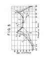
- Fig. 5 shows four attenuation characteristic curves (in dB) against frequency of various noise filters in accordance with the test scheme of Japanese Industrial Standard (JIS-c6904-1977) for suppression effect test circuits applied for symmetrical noise signal voltages developed over a 50Ω non-inductive (net equivalent) termination resistor connected to the output. The dotted line characteristic curve A represents the measuring values of a conventional noise filter as commercially available from TDK Corporation as product type ZBF253D-01 and comprising a series inductance L made of a bead core and a shunt Mylar capacitor C of approximately 0.01 uF connected as shown in Fig. 1. The known tested filter device had the dimensions of 4.8 mm in night and 6 mm for the long and 3 mm for the short diameters, respectively. Also, the dotted line characteristic cuver B represents the measuring result of a prior art noise filter B comprising a good electrically conductive aluminum band of 12 mm width and about 55 µm thickness wound with sixteen turns to obtain essentially the same capacitance (≃ 0.01 µF) as that of the above sample A.
- Represented by the characteristic curve C is the measuring result of a first embodiment of the noise filter according to this invention using an aluminum foil of 12 mm width and about 55 µm thickness as electrically conductive band 6 and an iron foil of 12 mm width and about 20 µm thickness as electromagnetically conductive band 9 both wound with seventeen turns with an appropriate insulating separator to obtain essentially the same capacitance (≃0.01 µF) as with the sample A. Also, represented by the solid line characteristic curve D, the measuring result of another embodiment of the noise filter according to this invention is plotted using 12 mm wide and about 20 µm thick iron foils as both electromagnetically conductive bands 6 and 9 wound with seventeen turns and an appropriate insulating separator to obtain a capacitance about 0.01 µF.
- It is apparent from the characteristic curve in Fig. 5 that the attenuation factor of the sample A is the lowest of the four samples at low and high frequencies. Both characteristic curves C and D are generally better than those of the prior art noise filters at almost all frequencies.
- Various samples with different parameters were made and tested for further demonstration of advantages of this invention in contrast to the prior art noise filters. The tested samples are as follows:
- This is the same as the aforementioned sample A, i.e. the commercially available noise filter ZBF253D-01 of TDK Corporation.
- A pair of non-magnetic, electrically conductive bands with 12 mm width and 20 µm of thickness were wound to a tubular form with a pair of 15 mm wide and 57 µm thick Mylar tapes leaving an air core of 4 mm in diameter. For three samples B-1, B-2 and B-3 a pair of 50 cm, 100 cm and 150 cm long aluminum foils were used and wound with 17, 28 and 38 turns, respectively.
- A 12 mm wide, 20 µm thick aluminum foil and iron foil of the same size were used as electrically conductive and electromagnetically conductive bands. Both bands were wound in a tubular form with a pair of 15 mm wide, 57 µm thick Mylar tapes therebetween leaving an air core of 4 mm in diameter. Three samples C-l, C-2 and C-3 use 50 cm, 100 cm and 150 cm long aluminum and iron foils were used and wound with 17, 28 and 38 turns, respectively.
- A pair of 12 mm wide, 20 µm thick iron foils were used as electromagnetically conductive foils 6 and 9 and were wound to a tubular form with a pair of 15 mm wide, 57 µm thick Mylar tapes therebetween leaving an air core of 4 mm in diameter. Three samples D-1, D-2 and D-3
use 50 cm, 100 cm and 150 cm long iron foils were used and wound with 17, 28 and 38 turns, respectively. - The various electrical characteristics of these samples B, C and D are given in Table 1.

- As is apparent from the data in Table 1, both inductance and Q factor are larger for samples C and D using electromagnetically conductive films for at least one of the conductive bands 9 and 6 as compared with the prior art noise filters using only aluminum foils. However, the capacitance remains substantially unchanged.
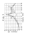
- Then, the measuring of the frequency - attenuation characteristics of these samples were carried out. The test results are shown in Figs. 6 through 8, wherein sample reference number of the aforementioned samples are showin in the drawings.
- It should be recognized that the samples had essentially the same number of turns of the windings and same size. Therefore, the differences in electrical performance are mainly responsible for the differences in materials of the conductive bands 6 and 9. The two embodiments according to this invention are generally superior in noise suppression properties over a wide frequency range. Especially, the sample D is better than any other samples.
- Figs. 9 and 10 each show characteristic curves of three samples C-1, C-2 and C-3 and D-1, D-2 and D-3 to demonstrate the effect of noise suppression due to different turns of the windings. It can be said that the noise filter performance is improved over a wide frequency range as the number of turns increases. The difference is significant at low frequencies. That is, the attenuation factor increases at low frequencies with large turns of the windings. Also shown in Figs. 9 and 10 are the characteristic curves of the conventional sample A to demonstrate the advantage of the present invention over the prior art noise filter composed of discrete elements.
- As is understood from the foregoing description and test results, the present invention modifies the conventional tubular capacitors in respect to the material of the conductive foil, thereby providing samples, compact, and less expensive noise filters with excellent noise suppression characteristic over wide frequency ranges. The noise filter can be made in large quantity by using conventional production facility with essentially no additional technique.
- Although I have described and demonstrated only preferred embodiments of this invention, the scope of this invention should not be limited to such embodiments. A person skilled in the art can easily modify this invention to best find his or her particular applications without departing from the scope of this invention. For example, the width of the conductive bands and the thickness of the insulating separators can be choosen depending on the current flowing through the coil and the applied voltage. The electromagnetically conductive film may be amorphous iron or MU-metal, or a lamination of electrically conductive and magnetically conductive layers. The noise filters find wide appreciations and a plurality of filters can be connected in cascade manner to provide higher noise attenuation. Such a multiple noise filter arrangement may be integrated in a single device. Therefore, such changes and modifications are deemed to be covered by the scope of the present invention.
Claims (8)
Applications Claiming Priority (4)
| Application Number | Priority Date | Filing Date | Title |
|---|---|---|---|
| JP8592583A JPS59212014A (en) | 1983-05-18 | 1983-05-18 | Noise filter |
| JP85925/83 | 1983-05-18 | ||
| JP13437783A JPS6027212A (en) | 1983-07-25 | 1983-07-25 | Noise filter |
| JP134377/83 | 1983-07-25 |
Publications (3)
| Publication Number | Publication Date |
|---|---|
| EP0126446A2 true EP0126446A2 (en) | 1984-11-28 |
| EP0126446A3 EP0126446A3 (en) | 1986-11-20 |
| EP0126446B1 EP0126446B1 (en) | 1989-11-23 |
Family
ID=26426933
Family Applications (1)
| Application Number | Title | Priority Date | Filing Date |
|---|---|---|---|
| EP84105637A Expired EP0126446B1 (en) | 1983-05-18 | 1984-05-17 | Noise filter and production method |
Country Status (4)
| Country | Link |
|---|---|
| US (1) | US4563658A (en) |
| EP (1) | EP0126446B1 (en) |
| KR (1) | KR900007925B1 (en) |
| DE (1) | DE3480576D1 (en) |
Cited By (3)
| Publication number | Priority date | Publication date | Assignee | Title |
|---|---|---|---|---|
| GB2180711A (en) * | 1985-09-18 | 1987-04-01 | Smiths Industries Plc | Reducing electromagnetic interference |
| EP0275093A3 (en) * | 1987-01-14 | 1989-07-26 | Takeshi Ikeda | Distributed constant type noise filter |
| EP0505909A1 (en) * | 1991-03-29 | 1992-09-30 | Hitachi Zosen Corporation | Apparatus for manufacturing electronic parts wrapped with conductive foil |
Families Citing this family (3)
| Publication number | Priority date | Publication date | Assignee | Title |
|---|---|---|---|---|
| DE3800572A1 (en) * | 1987-10-30 | 1989-07-20 | Vdo Schindling | COMBINATION INSTRUMENT FOR MOTOR VEHICLES |
| DE3909528A1 (en) * | 1988-03-23 | 1989-10-12 | Murata Manufacturing Co | IMPACT FILTER |
| RU36580U1 (en) * | 2003-06-30 | 2004-03-10 | Пак Юрий Эдуардович | NETWORK FILTER |
Citations (2)
| Publication number | Priority date | Publication date | Assignee | Title |
|---|---|---|---|---|
| GB743717A (en) * | 1953-02-09 | 1956-01-25 | British Dielectric Res Ltd | Improvements in the manufacture of electric circuit components |
| JPS5483736A (en) * | 1977-12-16 | 1979-07-04 | Matsushita Electric Ind Co Ltd | Noise filter |
Family Cites Families (3)
| Publication number | Priority date | Publication date | Assignee | Title |
|---|---|---|---|---|
| US2000441A (en) * | 1934-07-06 | 1935-05-07 | Bell Telephone Labor Inc | Filter |
| US2260296A (en) * | 1939-09-29 | 1941-10-28 | Bell Telephone Labor Inc | Electrical filter |
| US3141145A (en) * | 1961-09-20 | 1964-07-14 | Three Rivers Ind Inc | Feed-through smoothing filter |
-
1984
- 1984-05-02 KR KR1019840002357A patent/KR900007925B1/en not_active IP Right Cessation
- 1984-05-17 US US06/611,498 patent/US4563658A/en not_active Expired - Lifetime
- 1984-05-17 EP EP84105637A patent/EP0126446B1/en not_active Expired
- 1984-05-17 DE DE8484105637T patent/DE3480576D1/en not_active Expired
Patent Citations (2)
| Publication number | Priority date | Publication date | Assignee | Title |
|---|---|---|---|---|
| GB743717A (en) * | 1953-02-09 | 1956-01-25 | British Dielectric Res Ltd | Improvements in the manufacture of electric circuit components |
| JPS5483736A (en) * | 1977-12-16 | 1979-07-04 | Matsushita Electric Ind Co Ltd | Noise filter |
Non-Patent Citations (1)
| Title |
|---|
| PATENTS ABSTRACTS OF JAPAN, vol. 3, no. 106 (E-135), 7th September 1979, page 124 E-135; & JP-A-54 083 736 (MATSUSHITA DENKI SANGYO K.K.) 07-04-1979 * |
Cited By (5)
| Publication number | Priority date | Publication date | Assignee | Title |
|---|---|---|---|---|
| GB2180711A (en) * | 1985-09-18 | 1987-04-01 | Smiths Industries Plc | Reducing electromagnetic interference |
| US4751479A (en) * | 1985-09-18 | 1988-06-14 | Smiths Industries Public Limited Company | Reducing electromagnetic interference |
| GB2180711B (en) * | 1985-09-18 | 1989-08-23 | Smiths Industries Plc | Reducing electromagnetic interference |
| EP0275093A3 (en) * | 1987-01-14 | 1989-07-26 | Takeshi Ikeda | Distributed constant type noise filter |
| EP0505909A1 (en) * | 1991-03-29 | 1992-09-30 | Hitachi Zosen Corporation | Apparatus for manufacturing electronic parts wrapped with conductive foil |
Also Published As
| Publication number | Publication date |
|---|---|
| US4563658A (en) | 1986-01-07 |
| KR850000142A (en) | 1985-02-25 |
| EP0126446B1 (en) | 1989-11-23 |
| EP0126446A3 (en) | 1986-11-20 |
| KR900007925B1 (en) | 1990-10-23 |
| DE3480576D1 (en) | 1989-12-28 |
Similar Documents
| Publication | Publication Date | Title |
|---|---|---|
| US3603902A (en) | Miniature broad band low pass filters with multiturn tape wound inductors | |
| US5030933A (en) | Noise filter | |
| JPH0296312A (en) | Integrated power capacitor and inductor/transformer using insulated amorphous metal ribbon | |
| EP0126446B1 (en) | Noise filter and production method | |
| US3141145A (en) | Feed-through smoothing filter | |
| JPH10308315A (en) | Inductance element part | |
| US5844460A (en) | Wound, solid state inductor | |
| US3231798A (en) | Low inductance capacitor | |
| JP2004235709A (en) | Distributed constant filter element | |
| US4904973A (en) | Foil-roll electronic part | |
| EP0276684B1 (en) | Foil-roll electronic part and process of producing same | |
| JPH05291865A (en) | Lc filter | |
| JPH06231985A (en) | Common-mode choke coil | |
| JPH0998045A (en) | Noise filter | |
| US3081439A (en) | Electromagnetic delay lines | |
| JPH04133408A (en) | Plane-surface transformer | |
| JPH07320936A (en) | Laminated chip inductor | |
| US4908934A (en) | Process of producing a foil-roll electronic part | |
| JPS6050048B2 (en) | filter | |
| JPH06244030A (en) | Lc composite component | |
| JPH0243709A (en) | Noise filter | |
| JPH10270253A (en) | Inductance element and lc composite element | |
| JPH01289228A (en) | Noise filter | |
| US2001235A (en) | Device for unifying inductances, capacities, and resistances | |
| JPS59212013A (en) | Noise filter |
Legal Events
| Date | Code | Title | Description |
|---|---|---|---|
| PUAI | Public reference made under article 153(3) epc to a published international application that has entered the european phase |
Free format text: ORIGINAL CODE: 0009012 |
|
| AK | Designated contracting states |
Designated state(s): DE FR GB |
|
| PUAL | Search report despatched |
Free format text: ORIGINAL CODE: 0009013 |
|
| AK | Designated contracting states |
Kind code of ref document: A3 Designated state(s): DE FR GB |
|
| 17P | Request for examination filed |
Effective date: 19861216 |
|
| 17Q | First examination report despatched |
Effective date: 19890308 |
|
| GRAA | (expected) grant |
Free format text: ORIGINAL CODE: 0009210 |
|
| AK | Designated contracting states |
Kind code of ref document: B1 Designated state(s): DE FR GB |
|
| REF | Corresponds to: |
Ref document number: 3480576 Country of ref document: DE Date of ref document: 19891228 |
|
| ET | Fr: translation filed | ||
| PLBE | No opposition filed within time limit |
Free format text: ORIGINAL CODE: 0009261 |
|
| STAA | Information on the status of an ep patent application or granted ep patent |
Free format text: STATUS: NO OPPOSITION FILED WITHIN TIME LIMIT |
|
| 26N | No opposition filed | ||
| REG | Reference to a national code |
Ref country code: GB Ref legal event code: 732 |
|
| REG | Reference to a national code |
Ref country code: GB Ref legal event code: IF02 |
|
| PGFP | Annual fee paid to national office [announced via postgrant information from national office to epo] |
Ref country code: GB Payment date: 20030423 Year of fee payment: 20 |
|
| PGFP | Annual fee paid to national office [announced via postgrant information from national office to epo] |
Ref country code: FR Payment date: 20030520 Year of fee payment: 20 |
|
| PGFP | Annual fee paid to national office [announced via postgrant information from national office to epo] |
Ref country code: DE Payment date: 20030527 Year of fee payment: 20 |
|
| PG25 | Lapsed in a contracting state [announced via postgrant information from national office to epo] |
Ref country code: GB Free format text: LAPSE BECAUSE OF EXPIRATION OF PROTECTION Effective date: 20040516 |
|
| REG | Reference to a national code |
Ref country code: GB Ref legal event code: PE20 |