EP0126408A2 - Gas converter - Google Patents
Gas converter Download PDFInfo
- Publication number
- EP0126408A2 EP0126408A2 EP84105483A EP84105483A EP0126408A2 EP 0126408 A2 EP0126408 A2 EP 0126408A2 EP 84105483 A EP84105483 A EP 84105483A EP 84105483 A EP84105483 A EP 84105483A EP 0126408 A2 EP0126408 A2 EP 0126408A2
- Authority
- EP
- European Patent Office
- Prior art keywords
- gas
- reaction tower
- air
- converter according
- distributor head
- Prior art date
- Legal status (The legal status is an assumption and is not a legal conclusion. Google has not performed a legal analysis and makes no representation as to the accuracy of the status listed.)
- Withdrawn
Links
Images


Classifications
-
- C—CHEMISTRY; METALLURGY
- C10—PETROLEUM, GAS OR COKE INDUSTRIES; TECHNICAL GASES CONTAINING CARBON MONOXIDE; FUELS; LUBRICANTS; PEAT
- C10J—PRODUCTION OF PRODUCER GAS, WATER-GAS, SYNTHESIS GAS FROM SOLID CARBONACEOUS MATERIAL, OR MIXTURES CONTAINING THESE GASES; CARBURETTING AIR OR OTHER GASES
- C10J3/00—Production of combustible gases containing carbon monoxide from solid carbonaceous fuels
- C10J3/58—Production of combustible gases containing carbon monoxide from solid carbonaceous fuels combined with pre-distillation of the fuel
-
- C—CHEMISTRY; METALLURGY
- C10—PETROLEUM, GAS OR COKE INDUSTRIES; TECHNICAL GASES CONTAINING CARBON MONOXIDE; FUELS; LUBRICANTS; PEAT
- C10J—PRODUCTION OF PRODUCER GAS, WATER-GAS, SYNTHESIS GAS FROM SOLID CARBONACEOUS MATERIAL, OR MIXTURES CONTAINING THESE GASES; CARBURETTING AIR OR OTHER GASES
- C10J3/00—Production of combustible gases containing carbon monoxide from solid carbonaceous fuels
- C10J3/02—Fixed-bed gasification of lump fuel
- C10J3/06—Continuous processes
- C10J3/08—Continuous processes with ash-removal in liquid state
-
- C—CHEMISTRY; METALLURGY
- C10—PETROLEUM, GAS OR COKE INDUSTRIES; TECHNICAL GASES CONTAINING CARBON MONOXIDE; FUELS; LUBRICANTS; PEAT
- C10J—PRODUCTION OF PRODUCER GAS, WATER-GAS, SYNTHESIS GAS FROM SOLID CARBONACEOUS MATERIAL, OR MIXTURES CONTAINING THESE GASES; CARBURETTING AIR OR OTHER GASES
- C10J3/00—Production of combustible gases containing carbon monoxide from solid carbonaceous fuels
- C10J3/02—Fixed-bed gasification of lump fuel
- C10J3/20—Apparatus; Plants
- C10J3/30—Fuel charging devices
-
- C—CHEMISTRY; METALLURGY
- C10—PETROLEUM, GAS OR COKE INDUSTRIES; TECHNICAL GASES CONTAINING CARBON MONOXIDE; FUELS; LUBRICANTS; PEAT
- C10J—PRODUCTION OF PRODUCER GAS, WATER-GAS, SYNTHESIS GAS FROM SOLID CARBONACEOUS MATERIAL, OR MIXTURES CONTAINING THESE GASES; CARBURETTING AIR OR OTHER GASES
- C10J3/00—Production of combustible gases containing carbon monoxide from solid carbonaceous fuels
- C10J3/58—Production of combustible gases containing carbon monoxide from solid carbonaceous fuels combined with pre-distillation of the fuel
- C10J3/60—Processes
- C10J3/64—Processes with decomposition of the distillation products
- C10J3/66—Processes with decomposition of the distillation products by introducing them into the gasification zone
-
- C—CHEMISTRY; METALLURGY
- C10—PETROLEUM, GAS OR COKE INDUSTRIES; TECHNICAL GASES CONTAINING CARBON MONOXIDE; FUELS; LUBRICANTS; PEAT
- C10J—PRODUCTION OF PRODUCER GAS, WATER-GAS, SYNTHESIS GAS FROM SOLID CARBONACEOUS MATERIAL, OR MIXTURES CONTAINING THESE GASES; CARBURETTING AIR OR OTHER GASES
- C10J3/00—Production of combustible gases containing carbon monoxide from solid carbonaceous fuels
- C10J3/72—Other features
- C10J3/74—Construction of shells or jackets
-
- C—CHEMISTRY; METALLURGY
- C10—PETROLEUM, GAS OR COKE INDUSTRIES; TECHNICAL GASES CONTAINING CARBON MONOXIDE; FUELS; LUBRICANTS; PEAT
- C10J—PRODUCTION OF PRODUCER GAS, WATER-GAS, SYNTHESIS GAS FROM SOLID CARBONACEOUS MATERIAL, OR MIXTURES CONTAINING THESE GASES; CARBURETTING AIR OR OTHER GASES
- C10J2200/00—Details of gasification apparatus
- C10J2200/36—Moving parts inside the gasification reactor not otherwise provided for
-
- C—CHEMISTRY; METALLURGY
- C10—PETROLEUM, GAS OR COKE INDUSTRIES; TECHNICAL GASES CONTAINING CARBON MONOXIDE; FUELS; LUBRICANTS; PEAT
- C10J—PRODUCTION OF PRODUCER GAS, WATER-GAS, SYNTHESIS GAS FROM SOLID CARBONACEOUS MATERIAL, OR MIXTURES CONTAINING THESE GASES; CARBURETTING AIR OR OTHER GASES
- C10J2300/00—Details of gasification processes
- C10J2300/09—Details of the feed, e.g. feeding of spent catalyst, inert gas or halogens
- C10J2300/0913—Carbonaceous raw material
- C10J2300/0916—Biomass
-
- C—CHEMISTRY; METALLURGY
- C10—PETROLEUM, GAS OR COKE INDUSTRIES; TECHNICAL GASES CONTAINING CARBON MONOXIDE; FUELS; LUBRICANTS; PEAT
- C10J—PRODUCTION OF PRODUCER GAS, WATER-GAS, SYNTHESIS GAS FROM SOLID CARBONACEOUS MATERIAL, OR MIXTURES CONTAINING THESE GASES; CARBURETTING AIR OR OTHER GASES
- C10J2300/00—Details of gasification processes
- C10J2300/09—Details of the feed, e.g. feeding of spent catalyst, inert gas or halogens
- C10J2300/0913—Carbonaceous raw material
- C10J2300/093—Coal
-
- C—CHEMISTRY; METALLURGY
- C10—PETROLEUM, GAS OR COKE INDUSTRIES; TECHNICAL GASES CONTAINING CARBON MONOXIDE; FUELS; LUBRICANTS; PEAT
- C10J—PRODUCTION OF PRODUCER GAS, WATER-GAS, SYNTHESIS GAS FROM SOLID CARBONACEOUS MATERIAL, OR MIXTURES CONTAINING THESE GASES; CARBURETTING AIR OR OTHER GASES
- C10J2300/00—Details of gasification processes
- C10J2300/09—Details of the feed, e.g. feeding of spent catalyst, inert gas or halogens
- C10J2300/0913—Carbonaceous raw material
- C10J2300/0943—Coke
-
- C—CHEMISTRY; METALLURGY
- C10—PETROLEUM, GAS OR COKE INDUSTRIES; TECHNICAL GASES CONTAINING CARBON MONOXIDE; FUELS; LUBRICANTS; PEAT
- C10J—PRODUCTION OF PRODUCER GAS, WATER-GAS, SYNTHESIS GAS FROM SOLID CARBONACEOUS MATERIAL, OR MIXTURES CONTAINING THESE GASES; CARBURETTING AIR OR OTHER GASES
- C10J2300/00—Details of gasification processes
- C10J2300/09—Details of the feed, e.g. feeding of spent catalyst, inert gas or halogens
- C10J2300/0953—Gasifying agents
- C10J2300/0956—Air or oxygen enriched air
-
- C—CHEMISTRY; METALLURGY
- C10—PETROLEUM, GAS OR COKE INDUSTRIES; TECHNICAL GASES CONTAINING CARBON MONOXIDE; FUELS; LUBRICANTS; PEAT
- C10J—PRODUCTION OF PRODUCER GAS, WATER-GAS, SYNTHESIS GAS FROM SOLID CARBONACEOUS MATERIAL, OR MIXTURES CONTAINING THESE GASES; CARBURETTING AIR OR OTHER GASES
- C10J2300/00—Details of gasification processes
- C10J2300/09—Details of the feed, e.g. feeding of spent catalyst, inert gas or halogens
- C10J2300/0953—Gasifying agents
- C10J2300/0973—Water
- C10J2300/0976—Water as steam
-
- C—CHEMISTRY; METALLURGY
- C10—PETROLEUM, GAS OR COKE INDUSTRIES; TECHNICAL GASES CONTAINING CARBON MONOXIDE; FUELS; LUBRICANTS; PEAT
- C10J—PRODUCTION OF PRODUCER GAS, WATER-GAS, SYNTHESIS GAS FROM SOLID CARBONACEOUS MATERIAL, OR MIXTURES CONTAINING THESE GASES; CARBURETTING AIR OR OTHER GASES
- C10J2300/00—Details of gasification processes
- C10J2300/16—Integration of gasification processes with another plant or parts within the plant
- C10J2300/1603—Integration of gasification processes with another plant or parts within the plant with gas treatment
- C10J2300/1609—Post-reduction, e.g. on a red-white-hot coke or coal bed
-
- C—CHEMISTRY; METALLURGY
- C10—PETROLEUM, GAS OR COKE INDUSTRIES; TECHNICAL GASES CONTAINING CARBON MONOXIDE; FUELS; LUBRICANTS; PEAT
- C10J—PRODUCTION OF PRODUCER GAS, WATER-GAS, SYNTHESIS GAS FROM SOLID CARBONACEOUS MATERIAL, OR MIXTURES CONTAINING THESE GASES; CARBURETTING AIR OR OTHER GASES
- C10J2300/00—Details of gasification processes
- C10J2300/16—Integration of gasification processes with another plant or parts within the plant
- C10J2300/1671—Integration of gasification processes with another plant or parts within the plant with the production of electricity
-
- C—CHEMISTRY; METALLURGY
- C10—PETROLEUM, GAS OR COKE INDUSTRIES; TECHNICAL GASES CONTAINING CARBON MONOXIDE; FUELS; LUBRICANTS; PEAT
- C10J—PRODUCTION OF PRODUCER GAS, WATER-GAS, SYNTHESIS GAS FROM SOLID CARBONACEOUS MATERIAL, OR MIXTURES CONTAINING THESE GASES; CARBURETTING AIR OR OTHER GASES
- C10J2300/00—Details of gasification processes
- C10J2300/18—Details of the gasification process, e.g. loops, autothermal operation
- C10J2300/1861—Heat exchange between at least two process streams
- C10J2300/1869—Heat exchange between at least two process streams with one stream being air, oxygen or ozone
-
- C—CHEMISTRY; METALLURGY
- C10—PETROLEUM, GAS OR COKE INDUSTRIES; TECHNICAL GASES CONTAINING CARBON MONOXIDE; FUELS; LUBRICANTS; PEAT
- C10J—PRODUCTION OF PRODUCER GAS, WATER-GAS, SYNTHESIS GAS FROM SOLID CARBONACEOUS MATERIAL, OR MIXTURES CONTAINING THESE GASES; CARBURETTING AIR OR OTHER GASES
- C10J2300/00—Details of gasification processes
- C10J2300/18—Details of the gasification process, e.g. loops, autothermal operation
- C10J2300/1861—Heat exchange between at least two process streams
- C10J2300/1884—Heat exchange between at least two process streams with one stream being synthesis gas
-
- Y—GENERAL TAGGING OF NEW TECHNOLOGICAL DEVELOPMENTS; GENERAL TAGGING OF CROSS-SECTIONAL TECHNOLOGIES SPANNING OVER SEVERAL SECTIONS OF THE IPC; TECHNICAL SUBJECTS COVERED BY FORMER USPC CROSS-REFERENCE ART COLLECTIONS [XRACs] AND DIGESTS
- Y02—TECHNOLOGIES OR APPLICATIONS FOR MITIGATION OR ADAPTATION AGAINST CLIMATE CHANGE
- Y02P—CLIMATE CHANGE MITIGATION TECHNOLOGIES IN THE PRODUCTION OR PROCESSING OF GOODS
- Y02P20/00—Technologies relating to chemical industry
- Y02P20/10—Process efficiency
- Y02P20/129—Energy recovery, e.g. by cogeneration, H2recovery or pressure recovery turbines
Definitions
- the invention relates to a gas converter for the treatment of gases, in particular for the treatment of carbonization gas formed in the pyrolysis of waste and its dissociation in a reaction tower with an airtight supply device for coke or coal in the upper area, with a gas discharge opening, with a coke or coal bed , with a slag discharge device. and with an air and. Gas supply line,
- the smoldering gases can be processed in a gas converter or reaction tower.
- a mixture of carbonization gas, water vapor and coal dust is introduced from a carbonization drum in which the pyrolysis has taken place into the gas converter via the gas supply line, air being blown in under-stoichiometrically at the same time.
- Over a glowing coal bed not only is the carbon carried along partially burned, but there is also a partial oxidation of the carbonization gases, which results in the high temperature of approx. 1200 ° C for cracking the long-chain hydrocarbons to methane and hydrogen. To a small extent, carbon dioxide, carbon monoxide and simple hydrocarbons are also generated.
- the mixture of water vapor, CO 2 , CO, H 2 , methane, tar, phenol residues and nitrogen passes through the glowing coal bed, in which all subsequent reactions take place.
- the resulting gas mixture of hydrogen, carbon monoxide, short-chain hydrocarbons, the inert gases carbon dioxide and nitrogen, as well as small amounts of water vapor and higher hydrocarbons then leave the gas converter via the gas discharge opening.
- the gas is then generally cleaned of the entrained dust and finished in a gas cooling and gas washing system, after which it is sent for recycling.
- a recycling can e.g. in a gas engine or gas turbine with a generator to generate electricity.
- this gas can be used for waste heat or as a bypass for boiler systems or for other purposes, e.g. used in the chemical industry as synthesis gas.
- the slag discharge device for removing the slag consisted of a slide which was opened periodically accordingly.
- this method was very imprecise and led to a loss of coal or coke, because the opening times could not be regulated so precisely.
- the present invention is therefore based on the object of improving a gas converter of the type mentioned at the outset in such a way that it has a high degree of efficiency with a simple structure and little maintenance, the method being intended to run largely automatically.
- this object is achieved in that a rotating distributor head is arranged under the coke or coal bed at least approximately in the region of the longitudinal axis of the reaction tower, under which the gas and air supply lines open and several air / gas outlet openings are arranged distributed over its circumference.
- the rotating distribution head and the correspondingly supplied gas and air supply lines result in a very even distribution of the air / gas mixture in the carbon bed above. It is only necessary to ensure that the distributor head is made of a material that is sufficiently heat-resistant to the high temperatures that occur. For this, e.g. ceramic material can be used, which is also very hard.
- At least two rows of air / gas outlet openings lying one above the other can be arranged offset in the circumferential direction in the distributor head.
- the air / gas outlet openings can each open into recesses which widen outwards and which, viewed in cross section, give the distributor head at least approximately a star-shaped appearance.
- This configuration eliminates the need for screw connections, since the distributor head arranged in the lower area of the gas converter under the carbon bed sits securely on the drive shaft inserted into the gas converter from below due to its own weight.
- polygonal bore is eccentric to the center line of the distributor head.
- the distributor head executes a pivoting movement during its rotation, so that the slag cake in the discharge chute is hit like a hammer during the rotation of the distributor head and is thus crushed. In this way, blockages can be avoided and the slag can fall down on its own.
- a rotating slag trough can be arranged under the reaction tower, which is designed as a water bath and the edges of which project beyond the lower end of the reaction tower.
- the air supply line is connected to a Heilvoriser adopted that a debouching in the upper region in the peripheral wall of the reaction tower cold air duct, adjoining it in or arranged on the circumferential wall: Aufikikanäle and to the AIR SUPPLY line leading hot air outlet line.
- This configuration achieves air preheating in a simple manner, the reaction tower and thus also the gases to be drawn off being cooled in the upper region of the reaction tower at the same time.
- the design of the heating channels can be any.
- a very advantageous and effective design consists in the heating channels being designed as a labyrinth which extends at least partially over the circumference of the reaction tower and has shafts running in the vertical direction.
- a very advantageous further development of the invention which is also suitable for gas converters of the type mentioned at the outset, regardless of the configuration of the distributor head and / or the slag discharge device, consists in the feed device being designed as a cellular wheel sluice.
- the feed device being designed as a cellular wheel sluice.
- the required amount of coal or coke is now added continuously or at short periodic intervals.
- the addition can be controlled in a simple manner so that the coke or coal bed can be maintained at essentially the same height. With this configuration, a very uniform treatment of the gas with high efficiency is achieved. It is only necessary for the cellular wheel sluice to be made of a correspondingly heat-resistant material.
- a distribution fan is arranged below this feed device, the center of which is at least approximately in the region of the longitudinal axis of the reaction tower, with its center in radial distribution over the circumference spread several distribution trays of different lengths.
- the distribution compartments prevent in a simple manner that a conical structure is formed in the middle during filling. Rather, the coal or coke is distributed largely evenly into the interior of the reaction tower through the distribution channels. At the end of the distribution troughs, which are generally inclined towards the outside, coal or coke correspondingly falls down onto the coal bed, the uniform distribution being achieved due to its different length.
- the carbonization gas to be treated is generally contained in a horizontally lying, indirectly heated carbonization drum at a temperature of 400-500 ° C. with the exclusion of oxygen from the organic components. This pyrolysis process is well known, which is why it is not described in detail here.
- the gas converter has a reaction tower 1, which is provided with a lining 2 on its inside and is mounted on supports 3.
- the lower region of the reaction tower is formed from interchangeable ring segments 4.
- the reaction tower 1 is open on its underside, but projects with the lower ends of the ring segments 4 into a slag pan 7, which is filled with water during operation, to a level which lies above the lower ends of the ring segments 4.
- a slag pan 7 which is filled with water during operation, to a level which lies above the lower ends of the ring segments 4.
- the edges of the water bath 7 project beyond the lower end of the reaction tower 1 accordingly. In this way there is an air seal at the bottom.
- the slag pan 7 is designed as an annular channel, with a central drive shaft 8 for a distributor head 9 being carried out in the central region.
- the shaft bearing is of course also airtight here.
- a carbon bed 6 lies above it.
- the gas supply line 10 which is connected to a carbonization drum (not shown), also opens into the area of the distributor head is.
- the gas supply line 10 ends in an annular channel 11, from which a plurality of supply lines 12 lead in a vertical direction upwards over the circumference and end below the distributor head 9.
- an air supply line 13 which also ends in a ring line 14, which is located inside the ring line 11, the required air is also supplied via air lines 15 branching vertically upward from the ring line 14.
- the air lines 15 also end just below the distributor head 9. They are also preferably each arranged directly next to the gas supply lines 10.
- the slag pan 7 is set in rotation by a motor 16, while the distributor head 9 is set in rotation by a separate drive (not shown).
- the distributor head 9 made of ceramic material has a rotationally symmetrical shape that tapers towards the top. Furthermore, the distributor head 9 is provided with a hexagonal bore 100, which, however, to a small extent is offset from the central axis 17 of the distributor head. As a result, the distributor head executes an “egg-shaped” movement during the rotation, as a result of which an annular gap 18 between the distributor head 9 and the inner walls of the ring segments 4 changes.
- the annular gap 18 serves as an ejection chute for the slag falling down from the coke bed 6. The changing annular gap 18 crushes it and can fall into the water bath without hindrance.
- the distributor head 9 is distributed over its circumference with a plurality of air / gas outlet openings 19 and 20 which are arranged in two rows one above the other and offset from one another.
- the air / gas outlet openings 19 and 20 are connected to the underside of the distributor head 9 via connection bores 21 and 22 which are slightly inclined relative to the vertical direction. In this way, the air / gas outlet openings 19 and 20 receive the air / gas mixture from the feed lines 12 and 15.
- the air / gas outlet openings 19 and 20 each open into recesses 23 and 24 that widen outwards.
- the distributor head 9 thus has a star-shaped appearance in the area of the air / gas outlet openings 19 and 20.
- Part of the air / gas mixture will flow out laterally below the distributor head 9 above the ends of the feed lines 12 and 15, another part will flow out via the cutouts 23 and a third part will flow out through the cutout 24, with the cutouts 23 and 24 as can be seen are arranged offset to one another over the circumference of the distributor head 9.
- the air supply to the air supply line 13 takes place via a preheating device which has a cold air line 25 which opens into the peripheral wall of the reaction tower 1 in the upper combustion region.
- the structure of the air preheating device can be seen more clearly from FIGS. 7 and 8.
- the cold air line 25 is followed by a plurality of heating channels 26 arranged in the peripheral wall, which are in the form of a labyrinth in the vertical direction distributed over the circumferential wall.
- the heating channels 26 thus form vertical shafts, each of which is alternately connected on its underside or top with ring plates 27 and 28 which are arranged in the peripheral wall of the reaction tower 1. In this way, the supplied cold air 25 can flow through the shafts in the direction of the arrow (see FIG.
- a branch can also be provided in the hot air outlet line 29 with gate valves 30 (not shown in more detail), which, if necessary, can also be used to blow air laterally into the coke bed 6 via a ring line 31.
- a gas vent 32 is located in the upper area of the reaction tower 1.
- a cellular wheel sluice 33 is also arranged in the upper area, over which a funnel-shaped coke bunker 34 is located. The required amount of coke is introduced into the interior of the reaction container in an airtight manner via the cellular wheel sluice 33.
- the design of the distribution fan 35 can be seen more clearly from FIG. 7.
- the center point 36 of the distribution fan 35 lies at least approximately in the region of the longitudinal axis 37 of the reaction tower 1. From the center point 36, a plurality of outwardly inclined distribution channels 38 extend in a radial direction over the circumference. In particular, the adjacent distribution channels 38 have different lengths. This means that coke introduced via the rotary valve 33, which falls onto the distribution compartments 35 and is transported more or less to the outside depending on the length of the distribution channels 38, is distributed relatively evenly over the interior of the reaction tower 1 down onto the coke bed 6 Refill falls. In this way, a largely equalized level of the coke bed is maintained.
Abstract
Ein Gaswandler zur Aufbereitung von Gasen, insbesondere zur Aufbereitung von bei der Pyrolyse von Müll entstandenem Schwelgas und dessen Dissoziation ist mit einer luftdicht abschließenden Zufuhreinrichtung (33) für Koks oder Kohle im oberen Bereich, mit einer Gasabzugsöffnung (32), mit einem Koks- oder Kohlebett (6), mit einer Schlackeaustragseinrichtung (18, 7) und mit einer unter dem Koks- oder Kohlebett (6) einmündenden Luft- und Gaszufuhrleitung (13 bzw. 10) versehen. Der Reaktionsturm (1) ist mit einem rotierenden Verteilerkopf (9) versehen, unter dem die Gas- und die Luftzufuhrleitung (10 bzw. 13) münden. Die Zufuhreinrichtung ist als Zellenradschleuse (33) ausgebildet.
Description
Die Erfindung betrifft einen Gaswandler zur Aufbereitung von Gasen, insbesondere zur Aufbereitung von bei der Pyrolyse von Müll entstandenem Schwelgas und dessen Dissoziation in einem Reaktionsturm mit einer luftdicht abschließenden Zufuhreinrichtung für Koks oder Kohle im oberen Bereich, mit einer Gasabzugsöffnung, mit einem Koks- oder Kohlebett, mit einer Schlackeaustragseinrichtung. und mit einer Luft- und . Gaszufuhrleitung,The invention relates to a gas converter for the treatment of gases, in particular for the treatment of carbonization gas formed in the pyrolysis of waste and its dissociation in a reaction tower with an airtight supply device for coke or coal in the upper area, with a gas discharge opening, with a coke or coal bed , with a slag discharge device. and with an air and. Gas supply line,
In einem Gaswandler oder Reaktionsturm, können die Schwelgase aufbereitet werden.The smoldering gases can be processed in a gas converter or reaction tower.
Dies ist z.B. bei der Pyrolyse von Müll aus Haushaltungen, Gewerbe und Industrie der Fall, wobei die in den Abfällen enthaltenen organischen Bestandteile sowohl entgast als auch vergast werden. Das dabei gewonnene Gas ist für die direkte Verwertung noch nicht geeignet und wird deshalb erst in einem Gaswandler nachbehandelt.This is e.g. in the pyrolysis of waste from households, trade and industry, whereby the organic components contained in the waste are both degassed and gasified. The gas obtained is not yet suitable for direct recycling and is therefore only treated in a gas converter.
Ein Gemisch aus Schwelgas, Wasserdampf und Kohlenstaub wird aus einer Schweltrommel, in der die Pyrolyse stattgefunden hat, in den Gaswandler über die Gaszufuhrleitung eingebracht, wobei gleichzeitig Luft unterstöchiometrisch eingeblasen wird. Über einem glühenden Kohlebett wird nicht nur der mitgeführte Kohlenstoff teilweise verbrannt, sondern es erfolgt auch eine partielle Oxidation der Schwelgase, wodurch die hohe Temperatur von ca. 1200°C für die Crackung der langkettigen Kohlenwasserstoffe zu Methan und Wasserstoff erzielt wird. In geringem Umfang entstehen dabei auch Kohlendioxid, Kohlenmonoxid und einfache Kohlenwasserstoffe. In der anschließenden Dissoziationsphase durchläuft das Gemisch aus Wasserdampf, CO2, CO, H2, Methan, Teer, Phenolresten und Stickstoff das glühende Kohlebett, in dem dabei alle Folgereaktionen ablaufen.A mixture of carbonization gas, water vapor and coal dust is introduced from a carbonization drum in which the pyrolysis has taken place into the gas converter via the gas supply line, air being blown in under-stoichiometrically at the same time. Over a glowing coal bed, not only is the carbon carried along partially burned, but there is also a partial oxidation of the carbonization gases, which results in the high temperature of approx. 1200 ° C for cracking the long-chain hydrocarbons to methane and hydrogen. To a small extent, carbon dioxide, carbon monoxide and simple hydrocarbons are also generated. In the subsequent dissociation phase, the mixture of water vapor, CO 2 , CO, H 2 , methane, tar, phenol residues and nitrogen passes through the glowing coal bed, in which all subsequent reactions take place.
Das dabei entstehende Gasgemisch aus Wasserstoff, Kohlenmonoxid, kurzkettigen Kohlenwasserstoffen, den inerten Gasen Kohlendioxid und Stickstoff, sowie in geringen Mengen Wasserdampf und höhere Kohlenwasserstoffe verlassen anschließend den Gaswandler über die Gasabzugsöffnung. Anschließend wird das Gas dann im allgemeinen von dem mitgeführten Staub gereinigt und in einer Gas-Kühl- und Gas-Waschanlage endbehandelt, wonach es der Verwertung zugeführt wird. Eine Verwertung kann z.B. in einem Gasmotor oder einer Gasturbine mit einem Generator zur Stromerzeugung erfolgen. Weiterhin kann dieses Gas zur Abwärmenutzung oder als By-pass für Kesselanlagen oder für sonstige Zwecke, z.B. in der chemischen Industrie als Synthesegas verwendet werden.The resulting gas mixture of hydrogen, carbon monoxide, short-chain hydrocarbons, the inert gases carbon dioxide and nitrogen, as well as small amounts of water vapor and higher hydrocarbons then leave the gas converter via the gas discharge opening. The gas is then generally cleaned of the entrained dust and finished in a gas cooling and gas washing system, after which it is sent for recycling. A recycling can e.g. in a gas engine or gas turbine with a generator to generate electricity. Furthermore, this gas can be used for waste heat or as a bypass for boiler systems or for other purposes, e.g. used in the chemical industry as synthesis gas.
Die bisher bekannten Gaswandler weisen jedoch verschiedene Nachteile auf. So wurde bisher Kohle oder Koks im oberen Bereich des Gaswandlers einfach über ein Schleusensystem in das Innere chargenweise eingebracht. Dies bedeutet, daß das Kohlebett stets nahezu vollständig abgebrannt werden mußte und anschließend wurde eine neue Charge eingebracht. Durch diese schwankende Kohlenbetthöhe litt jedoch der Wirkungsgrad des Gaswandlers. Außerdem bildete sich ein kegelförmiges Kohlebett, was ebenfalls einen ungleichmäßigen Betrieb zur Folge hatte.However, the gas converters known to date have various disadvantages. So far, coal or coke in the upper area of the gas converter was simply introduced into the interior in batches using a lock system. This means that the coal bed always had to be almost completely burnt down and then a new batch was introduced. However, the efficiency of the gas converter suffered from this fluctuating coal bed height. A cone also formed shaped carbon bed, which also resulted in uneven operation.
Die Schlackeaustragseinrichtung zur Entfernung der Schlacke bestand aus einem Schieber, der entsprechend periodisch geöffnet wurde. Diese Methode war jedoch sehr ungenau und führte zu einem Verlust von Kohle oder Koks, denn die Öffnungszeiten ließen sich nicht so genau regeln.The slag discharge device for removing the slag consisted of a slide which was opened periodically accordingly. However, this method was very imprecise and led to a loss of coal or coke, because the opening times could not be regulated so precisely.
Auch die Luft- und die Gaszuführung erfolgte nicht überall gleichmäßig, was sich ebenfalls negativ auf das Ergebnis auswirkte.The air and gas supply were also not uniform everywhere, which also had a negative impact on the result.
Der vorliegenden Erfindung liegt daher die Aufgabe zugrunde einen Gaswandler der eingangs erwähnten Art so zu verbessern, daß er einen hohen Wirkungsgrad bei einfachem Aufbau und geringer Wartung aufweist, wobei das Verfahren weitgehend automatisch ablaufen soll.The present invention is therefore based on the object of improving a gas converter of the type mentioned at the outset in such a way that it has a high degree of efficiency with a simple structure and little maintenance, the method being intended to run largely automatically.
Erfindungsgemäß wird diese Aufgabe dadurch gelöst, daß unter dem Koks- oder Kohlebett wenigstens annähernd im Bereich der Längsachse des Reaktionsturmes ein rotierender Verteilerkopf angeordnet ist, unter den die Gas- und die Luftzufuhrleitung münden und über dessen Umfang verteilt mehrere Luft/Gasaustrittsöffnungen angeordnet sind.According to the invention, this object is achieved in that a rotating distributor head is arranged under the coke or coal bed at least approximately in the region of the longitudinal axis of the reaction tower, under which the gas and air supply lines open and several air / gas outlet openings are arranged distributed over its circumference.
Durch den rotierenden Verteilerkopf und die entsprechend zugeführten Gas- und Luftzufuhrleitungen erfolgt aufgrund der Rotation eine sehr gleichmäßige Verteilung des Luft/Gasgemisches in dem darüberliegenden Kohlebett. Es ist lediglich dafür zu sorgen, daß der Verteilerkopf aus einem Material besteht, das gegenüber den auftretenden hohen Temperaturen ausreichend hitzebeständig ist. Hierfür kann z.B. keramisches Material verwendet werden, das gleichzeitig auch sehr hart ist.Due to the rotation, the rotating distribution head and the correspondingly supplied gas and air supply lines result in a very even distribution of the air / gas mixture in the carbon bed above. It is only necessary to ensure that the distributor head is made of a material that is sufficiently heat-resistant to the high temperatures that occur. For this, e.g. ceramic material can be used, which is also very hard.
Für eine noch bessere und gleichmäßigere Verteilung des Luft/Gasgemisches können in dem Verteilerkopf wenigstens zwei übereinander liegende Reihen mit Luft/Gasaustrittsöffnungen in Umfangsrichtung versetzt zueinander liegend angeordnet sein.For an even better and more uniform distribution of the air / gas mixture, at least two rows of air / gas outlet openings lying one above the other can be arranged offset in the circumferential direction in the distributor head.
Hierbei können die Luft/Gasaustrittsöffnungen jeweils in nach außen hin sich erweiternden Aussparungen münden, die dem'Verteilerkopf - im Querschnitt gesehen - wenigstens annähernd ein sternförmiges Aussehen geben.In this case, the air / gas outlet openings can each open into recesses which widen outwards and which, viewed in cross section, give the distributor head at least approximately a star-shaped appearance.
Das Problem des Antriebes des Verteilerkopfes bei den vorhandenen hohen Temperaturen wurde erfindungsgemäß dadurch gelöst, daß dieser mit einer Mehrkantbohrung, vorzugsweise einer Sechskantbohrung, versehen ist, in die das Ende einer komplementär zu der Bohrung ausgebildeten und von unten her in den Reaktionsturm eingeführten Antriebswelle ragt.The problem of driving the distributor head at the high temperatures present was invented solved in that this is provided with a polygonal bore, preferably a hexagonal bore, into which the end of a complementary to the bore formed and inserted from below into the reaction tower driveshaft.
Durch diese Ausgestaltung können Schraubverbindungen entfallen, denn der im unteren Bereich des Gaswandlers unter dem Kohlebett angeordnete Verteilerkopf sitzt durch sein Eigengewicht sicher auf der von unten her in den Gaswandler eingeführten Antriebswelle.This configuration eliminates the need for screw connections, since the distributor head arranged in the lower area of the gas converter under the carbon bed sits securely on the drive shaft inserted into the gas converter from below due to its own weight.
Eine weitere sehr vorteilhafte'Weiterbildung der Erfindung besteht darin, daß die Mehrkantbohrung exzentrisch zur Mittellinie des Verteilerkopfes liegt.Another very advantageous further development of the invention is that the polygonal bore is eccentric to the center line of the distributor head.
Durch diese Ausgestaltung führt der Verteilerkopf während seiner Rotation eine Schwenkbewegung aus, so daß der Schlackekuchen in dem Auswurfschacht hammerartig während der Rotation des Verteilerkopfes getroffen und damit zermalmt wird. Auf diese Weise können Verstopfungen vermieden werden und die Schlacke kann selbständig nach unten fallen.As a result of this configuration, the distributor head executes a pivoting movement during its rotation, so that the slag cake in the discharge chute is hit like a hammer during the rotation of the distributor head and is thus crushed. In this way, blockages can be avoided and the slag can fall down on its own.
Als Schlackeaustragseinrichtung kann unter dem Reaktionsturm eine rotierende Schlackenwanne angeordnet sein, die als Wasserbad ausgebildet ist und deren Ränder außenseitig das untere Ende des Reaktionsturmes überragen.As a slag discharge device, a rotating slag trough can be arranged under the reaction tower, which is designed as a water bath and the edges of which project beyond the lower end of the reaction tower.
Durch diese Ausgestaltung wird zum einen der erforderliche luftdichte Abschluß beibehalten und zum anderen läßt sich damit die Schlacke in einfacher Weise austragen, was ggfo auch automatisch erfolgen kann. Gleichzeitig wird,die Schlacke dabei durch das Wasserbad abgekühlt.This configuration of the required air-tight seal is maintained on the one and on the other so that the slag can unsubscribe easily what o automatically if necessary can take place. At the same time, the slag is cooled by the water bath.
Da in dem unteren Bereich ein größerer Verschleiß auftreten wird, ist es von Vorteil, wenn dieser aus einzelnen auswechselbaren Ringsegmenten gebildet ist. Diese können dann im Bedarfsfalle auf einfache Weise und sehr schnell ausgewechselt werden.Since greater wear will occur in the lower area, it is advantageous if it is formed from individual interchangeable ring segments. If necessary, these can then be replaced quickly and easily.
Zur Erhöhung des Wirkungsgrades des Gaswandlers ist es von Vorteil, wenn die Luftzuleitung mit einer Luftvorwärmeeinrichtung verbunden ist, die eine im oberen Bereich in die Umfangswand des Reaktionsturmes einmündende Kaltluftleitung, sich daran anschließende in oder an der Umfangswand angeordnete:Aufheizkanäle und eine zu der Luftzuleitung führende Heißluftauslaßleitung aufweist.To increase the efficiency of the gas converter, it is advantageous if the air supply line is connected to a Luftvorwärmeeinrichtung that a debouching in the upper region in the peripheral wall of the reaction tower cold air duct, adjoining it in or arranged on the circumferential wall: Aufheizkanäle and to the AIR SUPPLY line leading hot air outlet line.
Durch diese Ausgestaltung wird auf einfache Weise eine Luftvorwärmung erreicht, wobei gleichzeitig auch der Reaktionsturm und damit auch die abzuziehenden Gase im oberen Bereich des Reaktionsturmes gekühlt werden.This configuration achieves air preheating in a simple manner, the reaction tower and thus also the gases to be drawn off being cooled in the upper region of the reaction tower at the same time.
Die Ausgestaltung der Aufheizkanäle kann beliebig sein. Eine sehr vorteilhafte und wirkungsvolle Ausbildung besteht jedoch darin, daß die Aufheizkanäle als wenigstens teilweise über den Umfang des Reaktionsturmes sich erstreckendes Labyrinth mit in vertikaler Richtung verlaufenden Schächten ausgebildet sind.The design of the heating channels can be any. A very advantageous and effective design, however, consists in the heating channels being designed as a labyrinth which extends at least partially over the circumference of the reaction tower and has shafts running in the vertical direction.
Durch diese Ausgestaltung wird eine sehr lange Aufheizstrecke auf geringstmöglichem Raum erreicht.With this configuration, a very long heating path is achieved in the smallest possible space.
Eine sehr vorteilhafte Weiterbildung der Erfindung, die auch unabhängig von der Ausgestaltung des Verteilerkopfes und/oder der Schlackenaustragseinrichtung für Gaswandler der eingangs erwähnten Art geeignet ist, besteht darin, daß die Zufuhreinrichtung als Zellenradschleuse ausgebildet ist. An Stelle einer Zugabe von Kohle oder Koks chargenweise über eine Schleuse mit zwei Absperrschiebern wird nunmehr kontinuierlich oder auch in kurzen periodischen Abständen die erforderliche Menge Kohle oder Koks zugegeben. Dabei kann die Zugabe auf einfache Weise so gesteuert werden, daß sich eine im wesentlichen gleiche Höhe des Koks- bzw. Kohlebettes einhalten läßt. Durch diese Ausgestaltung wird eine sehr gleichmäßige Behandlung des Gases mit hohem Wirkungsgrad erreicht. Es ist lediglich erforderlich, daß die Zellenradschleuse aus entsprechend hitzebeständigem Material ausgebildet ist.A very advantageous further development of the invention, which is also suitable for gas converters of the type mentioned at the outset, regardless of the configuration of the distributor head and / or the slag discharge device, consists in the feed device being designed as a cellular wheel sluice. Instead of adding coal or coke in batches via a lock with two gate valves the required amount of coal or coke is now added continuously or at short periodic intervals. The addition can be controlled in a simple manner so that the coke or coal bed can be maintained at essentially the same height. With this configuration, a very uniform treatment of the gas with high efficiency is achieved. It is only necessary for the cellular wheel sluice to be made of a correspondingly heat-resistant material.
Eine weitere sehr vorteilhafte Ausgestaltung im Zusammenhang mit einer Zufuhreinrichtung, die im oberen Bereich des Reaktionsturmes angeordnet ist,besteht darin, daß unter dieser Zufuhreinrichtung ein Verteilfächer angeordnet ist, dessen Mittelpunkt wenigstens annähernd im Bereich der Längsachse des Reaktionsturmes liegt, wobei von dessen Mittelpunkt aus in radialer Richtung über dem Umfang verteilt mehrere Verteilrinnen unterschiedlicher Länge ausgehen.Another very advantageous embodiment in connection with a feed device, which is arranged in the upper region of the reaction tower, is that a distribution fan is arranged below this feed device, the center of which is at least approximately in the region of the longitudinal axis of the reaction tower, with its center in radial distribution over the circumference spread several distribution trays of different lengths.
Durch den Verteilfächer wird in einfacher Weise verhindert, daß sich während der Befüllung in der Mitte ein kegelförmiger Aufbau bildet. Vielmehr wird die Kohle bzw. der Koks durch die Verteilrinnen weitgehend gleichmäßig in den Innenraum des Reaktionsturmes verteilt. Am Ende der Verteilrinnen, die im allgemeinen nach außen zu geneigt sind, fällt entsprechend Kohle bzw. Koks nach unten auf das Kohlebett, wobei durch dessen unterschiedlicher Länge die gleichmäßige Verteilung erreicht wird.The distribution compartments prevent in a simple manner that a conical structure is formed in the middle during filling. Rather, the coal or coke is distributed largely evenly into the interior of the reaction tower through the distribution channels. At the end of the distribution troughs, which are generally inclined towards the outside, coal or coke correspondingly falls down onto the coal bed, the uniform distribution being achieved due to its different length.
Nachfolgend ist anhand der Zeichnung ein Ausführungsbeispiel der Erfindung, aus dem weitere erfindungsgemäße Merkmale hervorgehen prinzipmäßig beschrieben.An exemplary embodiment of the invention, from which further features according to the invention emerge, is described in principle with reference to the drawing.
Es zeigen:
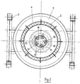
- Fig. 1 Eine Gesamtansicht eines Gaswandlers in schematischer Darstellung;
- Fig. 2 Einen Horizontalschnitt nach der Linie II - II der Fig. 1 in vergrößerter Darstellung;
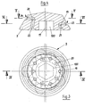
- Fig. 3 Eine Draufsicht auf den erfindungsgemäßen Verteilerkopf in vergrößerter Darstellung;
- Fig. 4 Einen Schnitt nach der Linie IV - IV der Fig. 3;
- Fig. 5 Einen Schnitt nach der Linie V - V der Fig. 4;
- Fig. 6 Einen Schnitt nach der Linie VI - VI der Fig. 4;
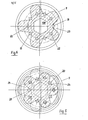
- Fig. 7 Einen Schnitt nach der Linie VII - VII der Fig 1 in vergrößerter Darstellung;
- Fig. 8 Einen Teilschnitt in Umfangsrichtung durch die Luftvorwärmeinrichtung nach der Linie VIII - VIII der Fig. 7.
- Fig. 1 An overall view of a gas converter in a schematic representation;
- Fig. 2 is a horizontal section along the line II - II of Figure 1 in an enlarged view.
- 3 shows a plan view of the distributor head according to the invention in an enlarged illustration;
- Fig. 4 is a section along the line IV - IV of Fig. 3;
- 5 shows a section along the line V - V of FIG. 4;
- Fig. 6 is a section along the line VI - VI of Fig. 4;
- 7 shows a section along the line VII - VII of FIG. 1 in an enlarged representation;
- 8 shows a partial section in the circumferential direction through the air preheating device along the line VIII-VIII of FIG. 7.
Das aufzubereitende Schwelgas wird im allgemeinen in einer horizontal liegenden indirekt beheizten Schweltrommel bei einer Temperatur von 400 - 500° C unter Ausschluß von Sauerstoff aus den organischen Bestandteilen enthalten. Dieses Pyrolyseverfahren ist hinreichend bekannt, weshalb es an dieser Stelle nicht näher beschrieben wird.The carbonization gas to be treated is generally contained in a horizontally lying, indirectly heated carbonization drum at a temperature of 400-500 ° C. with the exclusion of oxygen from the organic components. This pyrolysis process is well known, which is why it is not described in detail here.
Die Aufbereitung und Dissoziation dieses Schwelgases erfolgt in dem erfindungsgemäßen Gaswandler. Statt Schwelgas kann ggf. auch jede andere Gasart verwendet werden, die in einem Gaswandler aufbereitet werden soll.The processing and dissociation of this carbonization gas takes place in the gas converter according to the invention. Instead of carbonization gas, any other type of gas that is to be processed in a gas converter can also be used.
Der Gaswandler weist einen Reaktionsturm 1 auf, der auf seiner Innenseite mit einer Ausmauerung 2 versehen und auf Stützen 3 gelagert ist.The gas converter has a
Der untere Bereich des Reaktionsturmes ist aus auswechselbaren Ringsegmenten 4 gebildet.The lower region of the reaction tower is formed from
Der Reaktionsturm 1 ist auf seiner Unterseite offen, ragt jedoch mit den unteren Enden der Ringsegmente 4 in eine Schlackenwanne 7, die bei Betrieb mit Wasser gefülltist und zwar bis zu einem Niveau, das über den unteren Enden der Ringsegmente 4 liegt. Hierzu überragen die Ränder des Wasserbades 7 außenseitig das untere Ende des Reaktionsturmes 1 entsprechend. Auf diese Weise ist ein Luftabschluß nach unten gegeben.The
Die Schlackenwanne 7 ist als Ringkanal ausgebildet, wobei im mittleren Bereich eine zentrale Antriebswelle 8 für einen Verteilerkopf 9 durchgeführt ist. Die Wellenlagerung ist selbstverständlich auch hier luftdicht ausgeführt. In der Schlackenwanne 7 bis auf Höhe Unterkante Veiteilkopf 9 befindet sich Asche. Darüber liegt ein Kohlebett 6.The
In den Bereich des Verteilerkopfes mündet auch die Gaszufuhrleitung 10, die mit einer nicht dargestellten Schweltrommel verbunden ist. Die Gaszufuhrleitung 10 endet in einem Ringkanal 11, von dem aus in vertikaler Richtung nach oben über den Umfang verteilt mehrere Zuleitungen 12 führen, die unterhalb des Verteilerkopfes 9 enden.The
Über eine Luftzufuhrleitung 13, welche ebenfalls in einer Ringleitung 14 endet, welche im Inneren der Ringleitung 11 liegt,wird die erforderliche Luft ebenfalls über von der Ringleitung 14 vertikal nach oben abzweigende Luftleitungen 15 zugeführt. Die Luftleitungen 15 enden ebenfalls kurz unterhalb des Verteilerkopfes 9. Sie sind außerdem vorzugsweise jeweils direkt neben den Gaszuleitungen 10 angeordnet.Via an
Die Ausgestaltung der Luft/Gaszufuhrleitungen und des Verteilerkopfes sind aus den vergrößerten Darstellungen in den Figuren 2 - 6 deutlicher ersichtlich.The design of the air / gas supply lines and the distributor head can be seen more clearly from the enlarged representations in FIGS. 2-6.
Über einen Motor 16 wird die Schlackenwanne 7 in Rotation versetzt, während über einen gesonderten Antrieb (nicht dargestellt) der Verteilerkopf 9 ebenfalls in Rotation versetzt wird.The
Der Verteilerkopf 9 aus keramischem Material weist eine rotationssymmetrische Form auf, die nach oben zu sich verjüngt. Weiterhin ist der Verteilerkopf 9 mit einer Sechskantbohrung 100 versehen, die jedoch um ein geringes Maß von der Mittelachse 17 des Verteilerkopfes versetzt liegt. Dadurch führt der Verteilerkopf während der Rotation eine "eiförmige" Bewegung aus, wodurch sich ein Ringspalt 18 zwischen dem Verteilerkopf 9 und den Innenwänden der Ringsegmente 4 ändert. Der Ringspalt 18 dient als Auswurfschacht für die von dem Koksbett 6 nach unten fallende Schlacke. Durch den sich verändernden Ringspalt 18 wird diese dabei zermalmt und kann ohne Behinderung in das Wasserbad fallen.The
Der Verteilerkopf 9 ist über dessen Umfang verteilt mit mehreren Luft/Gasaustrittsöffnungen 19 und 20 versehen, die in zwei Reihen übereinander und versetzt zueinander angeordnet sind. Die Luft/Gasaustrittsöffnungen 19 und 20 stehen über leicht gegen die Vertikalrichtung schräggestellte Verbindungsbohrungen 21 und 22 mit der Unterseite des Verteilerkopfes 9 in Verbindung. Auf diese Weise erhalten die Luft/Gasaustrittsöffnungen 19 und 20 von den Zuleitungen 12 und 15 das Luft/Gasgemisch.The
Die Luft/Gasaustrittsöffnungen 19 und 20 münden jeweils in nach außen hin sich erweiternden Aussparungen 23 bzw. 24. Wie insbesondere aus den Figuren 5 und 6 ersichtlich ist, besitzt der Verteilerkopf 9 damit in dem Bereich der Luft/Gasaustrittsöffnungen 19 und 20 jeweils ein sternförmiges Aussehen.The air /
Durch diese Ausgestaltung des Verteilerkopfes in Verbindung mit den Gas- und Luftzuleitungen und Verteilleitungen ergibt sich eine optimale Verteilung des Luft/ Gasgemisches im Inneren des Reaktionsturmes 1.This configuration of the distributor head in connection with the gas and air supply lines and distribution lines results in an optimal distribution of the air / gas mixture in the interior of the
Ein Teil des Luft/Gasgemisches wird oberhalb der Enden der Zuleitungen 12 und 15 seitlich unter dem Verteilerkopf 9 ausströmen, ein weiterer Teil wird über die Aussparungen 23 und ein dritter Teil über die Aussparung 24 ausströmen, wobei - wie ersichtlich - die Aussparungen 23 und 24 über dem Umfang des Verteilerkopfes 9 versetzt zueinander angeordnet sind.Part of the air / gas mixture will flow out laterally below the
Die Luftzufuhr zu der Luftzufuhrleitung 13 erfolgt über eine Vorwärmeeinrichtung, die eine Kaltluftleitung 25 aufweist, die im oberen Brennbereich in die Umfangswand des Reaktionsturmes 1 einmündet. Der Aufbau der Luftvorwärmeeinrichtung ist aus den Figuren 7 und 8 deutlicher ersichtlich. An die Kaltluftleitung 25 schließen sich eine Vielzahl von in der Umfangswand angeordneten Aufheizkanälen 26 an, die in Form eines Labyrinthes in vertikaler Richtung über die Umfangswand verteilt verlaufen. Die Aufheizkanäle 26 bilden damit vertikale Schächte, wobei diese jeweils abwechselnd auf ihrer Unterseite bzw. ihrer Oberseite mit Ringblechen 27 bzw. 28 verbunden sind, welche in der Umfangswand des Reaktionsturmes 1 angeordnet sind. Auf diese Weise kann die zugeführte Kaltluft 25 in Pfeilrichtung (siehe Fig. 8) durch die Schächte strömen und wird damit während ihres Weges über nahezu den gesamten Umfang des Reaktionsturmes 1 stark erhitzt, bevor sie über eine Heißluftauslaßleitung 29 zu der Luftzufuhrleitung 13 geführt wird. Zur besseren Steuerung des Gaswandlers, insbesonders während der Aufheizphase, kann in der Heißluftauslaßleitung 29 noch eine Abzweigung mit nicht näher dargestellten Absperrschiebern 30 vorgesehen sein, wodurch im Bedarfsfalle auch Luft direkt über eine Ringleitung 31 in das Koksbett 6 seitlich eingeblasen werden kann.The air supply to the
. Im oberen Bereich des Reaktionsturmes 1 befindet sich ein Gasabzug 32. Ebenfalls im oberen Bereich ist eine Zellenradschleuse 33 angeordnet, über der ein trichterförmiger Koksbunker 34 liegt. Über die Zellenradschleuse 33 wird die erforderliche Koksmenge luftdicht in das Innere des Reaktionsbehälters eingebracht.. A
Zusätzlich befindet sich in dem oberen Bereich des Reaktionsturmes 1 unterhalb der Zellenradschleuse 33 ein Verteilfächer 35, welcher im Querschnitt gesehen kegelförmig ausgebildet ist.In addition, in the upper area of the
Die Ausgestaltung des Verteilfächers 35 ist aus der Fig. 7 deutlicher ersichtlich. Der Mittelpunkt 36 des Verteilfächers 35 liegt wenigstens annähernd im Bereich der Längsachse 37 des Reaktionsturmes 1. Von dem Mittelpunkt 36 aus gehen in radialer Richtung über den Umfang verteilt mehrere nach außen geneigte Verteilrinnen 38 ab. Insbesondere die nebeneinander liegenden Verteilrinnen 38 weisen unterschiedliche Längen auf. Dies bedeutet, daß über die Zellenradschleuse 33 eingebrachter Koks, der auf den Verteilfächer 35 fällt und dabei je nach Länge der Verteilrinnen 38 mehr oder weniger nach außen transportiert wird, relativ gleichmäßig über den Innenraum des Reaktionsturmes 1 verteilt nach unten auf das Koksbett 6 zu dessen Nachfüllung fällt. Auf diese Weise wird ein weitgehend egalisiertes Niveau des Koksbettes eingehalten.The design of the
Claims (14)
und Gaszufuhrleitung
dadurch gekennzeichnet, daß unter dem Koks- oder Kohlebett (6) wenigstens annähernd im Bereich der Längsachse des Reaktionsturmes (1) ein rotierender Verteilerkopf (9) angeordnet ist, unter dem die Gas- und die Luftzufuhrleitung (10,13) münden und über dessen Umfang verteilt mehrere Luft/ Gasaustrittsöffnungen (19, 20) angeordnet sind.1) Gas converter for the treatment of gases, in particular for the treatment of carbonization gas formed in the pyrolysis of waste and its dissociation in a reaction tower with an airtight supply device for coke or coal in the upper area, with a gas discharge opening, with a coke or coal bed, with a slag discharge device and with an air
and gas supply line
characterized in that under the coke or coal bed (6) at least approximately A rotating distributor head (9) is arranged in the region of the longitudinal axis of the reaction tower (1), under which the gas and air supply lines (10, 13) open and several air / gas outlet openings (19, 20) are arranged distributed over the circumference.
dadurch gekennzeichnet, daß in dem Verteilerkopf (9) wenigstens zwei übereinander liegende Reihen mit Luft/Gasaustrittsöffnungen (19, 20) in Umfangsrichtung versetzt zueinander liegend angeordnet sind.2) Gas converter according to claim 1
characterized in that in the distributor head (9) at least two rows one above the other with air / gas outlet openings (19, 20) are arranged offset to one another in the circumferential direction.
dadurch gekennzeichnet, daß die Luft/Gasaustrittsöffnungen (19, 20) jeweils in nach außen hin sich erweiternden Aussparungen (23, 24) münden, die dem Verteilerkopf (9) - im Querschnitt gesehen - in diesen Bereichen wenigstens annähernd ein sternförmiges Aussehen geben.3) Gas converter according to claim 1 or 2
characterized in that the air / gas outlet openings (19, 20) each open into recesses (23, 24) which widen outwards and which, viewed in cross section, give the distributor head (9) at least approximately a star-shaped appearance in these areas.
dadurch gekennzeichnet, daß der Verteilerkopf (9) mit einer Mehrkantbohrung (100), vorzugsweise einer Sechskantbohrung, versehen ist, in die das Ende einer komplementär zu der Bohrung ausgebildeten und von unten her in den Reaktionsturm eingeführten Antriebswelle (8) ragt.4) Gas converter according to one of claims 1-3
characterized in that the distributor head (9) is provided with a polygonal bore (100), preferably a hexagonal bore, in which projects the end of a drive shaft (8) which is designed to be complementary to the bore and is inserted into the reaction tower from below.
dadurch gekennzeichnet, daß die Mehrkanbohrung (100) exzentrisch zur Mittellinie (17) des Verteilerkopfes (9) liegt, und daß ein Ringspalt (18) zwischen dem Verteilerkopf (9) und der Umfangswand des Reaktionsturmes (1) in diesem Bereich einen Auswurfschacht für die Schlacke bildet.5) Gas converter according to claim 4
characterized in that the multi-channel bore (100) is eccentric to the center line (17) of the distributor head (9), and in that an annular gap (18) between the distributor head (9) and the peripheral wall of the reaction tower (1) in this area an ejection chute for the Forms slag.
dadurch gekennzeichnet , daß die Mittellinie der Antriebswelle (8) mit der Längsachse des Reaktionsturmes (1) koaxial ist.6) Gas converter according to claim 5
characterized in that the center line of the drive shaft (8) is coaxial with the longitudinal axis of the reaction tower (1).
dadurch gekennzeichnet, daß der Verteilerkopf (9) aus keramischem Material besteht.7) Gas converter according to one of claims 1-6
characterized in that the distributor head (9) consists of ceramic material.
dadurch gekennzeichnet , daß als Schlackenaustragseinrichtung unter dem Reaktionsturm (1) eine rotierende Schlackenwanne (7) angeordnet ist, die als Wasserbad ausgebildet ist, deren Ränder außenseitig das untere Ende des Rekationsturmes (1) überrageno 8) Gas converter according to one of claims 1-7
characterized in that a rotating slag trough (7) is arranged as a slag discharge device under the reaction tower (1), which is formed as a water bath whose edges project beyond the lower end of Rekationsturmes (1) on the outside o
dadurch gekennzeichnet, daß die Zufuhreinrichtung als Zellenradschleuse (33) ausgebildet ist.12) Gas converter for the treatment of gases, in particular for the treatment of carbonization gas produced during the pyrolysis of waste and its dissociation in a reaction tower with an airtight supply device for coke or coal in the upper area, with a gas discharge opening, with a coke or coal bed, with a slag discharge device and with an air and gas supply line
characterized in that the feed device is designed as a cellular wheel sluice (33).
dadurch gekennzeichnet, daß im Innenraum des Reaktionsturmes (1) unter der Zufuhreinrichtung (33) ein Verteilfächer (35) angeordnet ist, dessen Mittelpunkt (36) wenigstens annähernd im Bereich der Längsachse des Reaktionsturmes (1) liegt, wobei von dessem Mittelpunkt (36) aus in radialer Richtung über den Umfang verteilt mehrere nach außen geneigte Verteilrinnen (38) unterschiedlicher Länge ausgehen.13) Gas converter according to claim 12
characterized in that a distribution compartment (35) is arranged in the interior of the reaction tower (1) below the feed device (33), the center point (36) of which lies at least approximately in the region of the longitudinal axis of the reaction tower (1), a plurality of outwardly inclined distribution channels (38) of different lengths starting from its center point (36) in the radial direction over the circumference.
Applications Claiming Priority (2)
| Application Number | Priority Date | Filing Date | Title |
|---|---|---|---|
| DE19833317977 DE3317977A1 (en) | 1983-05-18 | 1983-05-18 | GAS CONVERTER |
| DE3317977 | 1983-05-18 |
Publications (2)
| Publication Number | Publication Date |
|---|---|
| EP0126408A2 true EP0126408A2 (en) | 1984-11-28 |
| EP0126408A3 EP0126408A3 (en) | 1987-09-30 |
Family
ID=6199212
Family Applications (1)
| Application Number | Title | Priority Date | Filing Date |
|---|---|---|---|
| EP84105483A Withdrawn EP0126408A3 (en) | 1983-05-18 | 1984-05-15 | Gas converter |
Country Status (4)
| Country | Link |
|---|---|
| US (1) | US4538528A (en) |
| EP (1) | EP0126408A3 (en) |
| JP (1) | JPS6035093A (en) |
| DE (1) | DE3317977A1 (en) |
Cited By (3)
| Publication number | Priority date | Publication date | Assignee | Title |
|---|---|---|---|---|
| EP0136255A2 (en) * | 1983-09-28 | 1985-04-03 | Herwig Michel-Kim | Reactor for producing generatorgas from combustible waste products |
| EP0718391A2 (en) * | 1994-11-22 | 1996-06-26 | DBI DEUTSCHES BRENNSTOFFINSTITUT ROHSTOFF & ANLAGENTECHNIK GmbH | Method and apparatus for recovering useful gas by pyrolysis |
| EP0750657A1 (en) * | 1994-03-16 | 1997-01-02 | American High Temp., Inc. | Gas conditioner apparatus and method |
Families Citing this family (5)
| Publication number | Priority date | Publication date | Assignee | Title |
|---|---|---|---|---|
| CA1238189A (en) * | 1984-11-27 | 1988-06-21 | Philippus J. Meyer | Gasification of coal |
| US4584947A (en) * | 1985-07-01 | 1986-04-29 | Chittick Donald E | Fuel gas-producing pyrolysis reactors |
| DE3727004A1 (en) * | 1987-08-13 | 1989-02-23 | Pyrolyse Kraftanlagen Pka | METHOD AND INSTALLATION FOR RECOVERING RECYCLABLE GAS FROM MUEL BY PYROLYSIS |
| DE3806365C1 (en) * | 1988-02-27 | 1989-07-20 | Veba Oel Entwicklungs-Gesellschaft Mbh, 4650 Gelsenkirchen, De | |
| DE3924626A1 (en) * | 1989-07-26 | 1991-01-31 | Forschungszentrum Juelich Gmbh | GASIFICATION REACTOR FOR COMBUSTIBLE SOLIDS |
Citations (5)
| Publication number | Priority date | Publication date | Assignee | Title |
|---|---|---|---|---|
| US1413400A (en) * | 1922-01-14 | 1922-04-18 | Goehtz Hermann | Stationary grate for furnaces |
| DE403003C (en) * | 1924-09-27 | Curt Loesche E | Loading device for shaft ovens and gas generators | |
| DE466963C (en) * | 1928-10-16 | J Et A Moussiaux & Freres Sa | Charging device with fixed distributor for shaft ovens, especially for gas generators | |
| DE2436268A1 (en) * | 1974-07-27 | 1976-02-12 | Ernst Kirchgaessner | Low-grade fuel gasification - with two rotary grate producers passing gasification gases through material for complete combustion |
| EP0012307A2 (en) * | 1978-12-07 | 1980-06-25 | Saarberg-Fernwärme GmbH | Rotary grate for a gasification and/or a combustion reactor |
Family Cites Families (6)
| Publication number | Priority date | Publication date | Assignee | Title |
|---|---|---|---|---|
| GB113182A (en) * | 1917-04-10 | 1918-02-14 | John Stewart | Improvements in and relating to Gas Producers. |
| US2147324A (en) * | 1936-01-16 | 1939-02-14 | Koppers Co Inc | Gas producer |
| US2548086A (en) * | 1946-05-27 | 1951-04-10 | Wests Gas Improvement Co Ltd | Gas producer, including rotatable ash breaking grate means |
| DE2432504B2 (en) * | 1974-07-04 | 1976-12-16 | Kiener, Karl, Dipl.-Ing., 7080 Goldshöfe | PROCESS AND SYSTEM FOR PRODUCING COMBUSTION GASES FROM COMPONENT DOMESTIC AND INDUSTRIAL MANUFACTURING ETC. |
| DE2736687A1 (en) * | 1977-08-16 | 1979-03-01 | Metallgesellschaft Ag | METHOD AND DEVICE FOR THE GASIFICATION OF GRAINED COAL AT INCREASED PRESSURE |
| US4274341A (en) * | 1978-12-07 | 1981-06-23 | Ozaltay Huseyin C | Coal gasifying burner with rotating grill |
-
1983
- 1983-05-18 DE DE19833317977 patent/DE3317977A1/en active Granted
-
1984
- 1984-05-15 EP EP84105483A patent/EP0126408A3/en not_active Withdrawn
- 1984-05-16 US US06/610,677 patent/US4538528A/en not_active Expired - Fee Related
- 1984-05-18 JP JP59100358A patent/JPS6035093A/en active Pending
Patent Citations (5)
| Publication number | Priority date | Publication date | Assignee | Title |
|---|---|---|---|---|
| DE403003C (en) * | 1924-09-27 | Curt Loesche E | Loading device for shaft ovens and gas generators | |
| DE466963C (en) * | 1928-10-16 | J Et A Moussiaux & Freres Sa | Charging device with fixed distributor for shaft ovens, especially for gas generators | |
| US1413400A (en) * | 1922-01-14 | 1922-04-18 | Goehtz Hermann | Stationary grate for furnaces |
| DE2436268A1 (en) * | 1974-07-27 | 1976-02-12 | Ernst Kirchgaessner | Low-grade fuel gasification - with two rotary grate producers passing gasification gases through material for complete combustion |
| EP0012307A2 (en) * | 1978-12-07 | 1980-06-25 | Saarberg-Fernwärme GmbH | Rotary grate for a gasification and/or a combustion reactor |
Cited By (6)
| Publication number | Priority date | Publication date | Assignee | Title |
|---|---|---|---|---|
| EP0136255A2 (en) * | 1983-09-28 | 1985-04-03 | Herwig Michel-Kim | Reactor for producing generatorgas from combustible waste products |
| EP0136255A3 (en) * | 1983-09-28 | 1986-01-22 | Herwig Michel-Kim | Reactor for producing generatorgas from combustible waste products |
| EP0750657A1 (en) * | 1994-03-16 | 1997-01-02 | American High Temp., Inc. | Gas conditioner apparatus and method |
| EP0750657A4 (en) * | 1994-03-16 | 1997-11-05 | American High Temp Inc | Gas conditioner apparatus and method |
| EP0718391A2 (en) * | 1994-11-22 | 1996-06-26 | DBI DEUTSCHES BRENNSTOFFINSTITUT ROHSTOFF & ANLAGENTECHNIK GmbH | Method and apparatus for recovering useful gas by pyrolysis |
| EP0718391A3 (en) * | 1994-11-22 | 1997-04-02 | Deutsches Brennstoffinst | Method and apparatus for recovering useful gas by pyrolysis |
Also Published As
| Publication number | Publication date |
|---|---|
| DE3317977C2 (en) | 1988-10-06 |
| EP0126408A3 (en) | 1987-09-30 |
| DE3317977A1 (en) | 1984-11-22 |
| JPS6035093A (en) | 1985-02-22 |
| US4538528A (en) | 1985-09-03 |
Similar Documents
| Publication | Publication Date | Title |
|---|---|---|
| DE3049250C2 (en) | Equipment with smoldering drum and shaft furnace | |
| EP1226222B1 (en) | Method for gasifying organic materials and mixtures of materials | |
| DE2927240C2 (en) | Method and device for gasifying lumpy fuels with pre-carbonization and cracking of the carbonization gases in the gas generator | |
| CH615215A5 (en) | ||
| DE2651302B2 (en) | Device for generating distillation gas from waste | |
| DE102008058602B4 (en) | In the form of a moving bed gasifier and method of operating such in an arrangement for the thermal decomposition of waste products and waste | |
| EP1248828B1 (en) | Device and method for the production of fuel gases | |
| DE60033782T2 (en) | METHOD FOR GASIFYING CARBON CONTAINING FUELS IN A FIXED BEDGED GASER | |
| DE945503C (en) | Method and device for carrying out chemical reactions in a fluidized bed | |
| DE3216836C2 (en) | ||
| DE3317977C2 (en) | ||
| DE2346833C3 (en) | Method for cooling the rotating grate bearings of a gas generator | |
| EP0055440A1 (en) | Process and plant for the continuous production of combustible gas from organic waste materials | |
| DE3239624C2 (en) | ||
| CH283414A (en) | Method and device for carrying out processes in which finely divided solid substances are brought into contact with gases. | |
| EP3485956A1 (en) | Pyrolytic gas generator | |
| DE4220265C1 (en) | Prodn. of gasification material in sloping bed reactor | |
| EP0431077B1 (en) | Process and device for the heat treatment of gasified material | |
| DE102013015920A1 (en) | Device in the form of a 3-zone carburetor and method for operating such a carburetor for the thermal conversion of waste products and wastes | |
| DE2735130C3 (en) | Shaft furnace for the pyrolysis of pelletized waste | |
| DE3816085C2 (en) | ||
| DE3245104C2 (en) | Shaft generator for generating flammable gases from carbon-containing fuels, in particular biomass, waste, household waste and the like. | |
| DE102006058673A1 (en) | Weak gas producing device for energy production, has helical conveyor i.e. agitation device, and inner wall of reactors arranged for maximum temperature adapted materials obtained in thermal processes | |
| DE840571C (en) | Method and device for flushing gas and gasifying ash-rich fuels in continuously operated cross-flow ovens | |
| EP0568104B1 (en) | Pyrolysis and combustion installation |
Legal Events
| Date | Code | Title | Description |
|---|---|---|---|
| PUAI | Public reference made under article 153(3) epc to a published international application that has entered the european phase |
Free format text: ORIGINAL CODE: 0009012 |
|
| AK | Designated contracting states |
Designated state(s): FR GB IT SE |
|
| PUAL | Search report despatched |
Free format text: ORIGINAL CODE: 0009013 |
|
| AK | Designated contracting states |
Kind code of ref document: A3 Designated state(s): FR GB IT SE |
|
| 17P | Request for examination filed |
Effective date: 19871027 |
|
| 17Q | First examination report despatched |
Effective date: 19880811 |
|
| PGFP | Annual fee paid to national office [announced via postgrant information from national office to epo] |
Ref country code: SE Payment date: 19890906 Year of fee payment: 6 |
|
| STAA | Information on the status of an ep patent application or granted ep patent |
Free format text: STATUS: THE APPLICATION HAS BEEN WITHDRAWN |
|
| 18W | Application withdrawn |
Withdrawal date: 19890728 |
|
| R18W | Application withdrawn (corrected) |
Effective date: 19890728 |
|
| RIN1 | Information on inventor provided before grant (corrected) |
Inventor name: FAEHNLE, ERICH, ING. (GRAD.) |