EP0125932A2 - Control apparatus for and method of operating automatic filling machine - Google Patents
Control apparatus for and method of operating automatic filling machine Download PDFInfo
- Publication number
- EP0125932A2 EP0125932A2 EP84303474A EP84303474A EP0125932A2 EP 0125932 A2 EP0125932 A2 EP 0125932A2 EP 84303474 A EP84303474 A EP 84303474A EP 84303474 A EP84303474 A EP 84303474A EP 0125932 A2 EP0125932 A2 EP 0125932A2
- Authority
- EP
- European Patent Office
- Prior art keywords
- revolution
- time
- rotary feed
- feed means
- predetermined time
- Prior art date
- Legal status (The legal status is an assumption and is not a legal conclusion. Google has not performed a legal analysis and makes no representation as to the accuracy of the status listed.)
- Granted
Links
Images


Classifications
-
- B—PERFORMING OPERATIONS; TRANSPORTING
- B65—CONVEYING; PACKING; STORING; HANDLING THIN OR FILAMENTARY MATERIAL
- B65B—MACHINES, APPARATUS OR DEVICES FOR, OR METHODS OF, PACKAGING ARTICLES OR MATERIALS; UNPACKING
- B65B1/00—Packaging fluent solid material, e.g. powders, granular or loose fibrous material, loose masses of small articles, in individual containers or receptacles, e.g. bags, sacks, boxes, cartons, cans, or jars
- B65B1/30—Devices or methods for controlling or determining the quantity or quality or the material fed or filled
- B65B1/32—Devices or methods for controlling or determining the quantity or quality or the material fed or filled by weighing
-
- B—PERFORMING OPERATIONS; TRANSPORTING
- B65—CONVEYING; PACKING; STORING; HANDLING THIN OR FILAMENTARY MATERIAL
- B65B—MACHINES, APPARATUS OR DEVICES FOR, OR METHODS OF, PACKAGING ARTICLES OR MATERIALS; UNPACKING
- B65B1/00—Packaging fluent solid material, e.g. powders, granular or loose fibrous material, loose masses of small articles, in individual containers or receptacles, e.g. bags, sacks, boxes, cartons, cans, or jars
- B65B1/04—Methods of, or means for, filling the material into the containers or receptacles
- B65B1/10—Methods of, or means for, filling the material into the containers or receptacles by rotary feeders
- B65B1/12—Methods of, or means for, filling the material into the containers or receptacles by rotary feeders of screw type
Definitions
- the auger, pump rotor, or other rotational member is driven by a prime mover, such as an electric motor, through a clutch-brake mechanism which connects the driving shaft of the motor to the driven shaft of the rotational member.
- the clutch-brake mechanism is controlled to rotate the driven shaft for a preselected number of revolutions by a device which counts the number of revolutions. This is a relatively accurate way of volumetrically dispensing material since the amount of material dispensed by each revolution of the auger or pump can be accurately determined. For example, for each revolution of an auger of known pitch and diameter, the volume of material dispensed from its discharge end can be determined. By appropriate control, the auger can be made to run through sequential cycles of a predetermined number of turns.
- a predetermined volume of material is discharged into a container positioned by mechanised packaging devices at the discharge end of the feed mechanism.
- mechanised packaging line devices for sequentially positioning containers made of paper, metal, plastics or glass are well-known.
- the number of revolutions is a measure of the volume of material that has been-dispensed.
- the second method is to measure the time period over which the feed mechanism is being driven at a constant speed.
- devices for counting the number of revolutions include counters directly linked by gearing to the output side of the clutch-brake mechanism mentioned above, and shaft encoders directly or indirectly coupled to the driven shaft which generate a given number of pulses for each complete revolution of the driven shaft. When the correct count is reached, the driven shaft is disengaged from the driving shaft and braked by the clutch-brake mechanism.
- the timed method of controlling the number ofrevo- lutions is less accurate than the count method, although in certain cases the timed method of controlling the number of revolutions may yield acceptable accuracy.
- a filler apparatus of the type having a hopper means for storing material to be dispensed by the filler, rotary feed means operatively associated with the hopper means for dispensing controlled volumes of material from a discharge opening in the hopper means into containers to be filled, said volumes being directly proportional to the time of revolution of the rotary feed means, cyclically engageable drive means for rotating the rotary feed means, and brake means for stopping the rotation of the rotary feed means after a predetermined time of revolution, characterised by
- Apparatus lO has a hopper 12 for storing material to be dispensed.
- Hopper 12 has generally the shape of an inverted cone.
- the bottom end of the hopper 12 terminates in a generally cylindrical outlet 14.
- a feed auger 18 is fitted within the outlet 14 at the bottom end of hopper 12. Rotation of the auger 18 causes material 16 to be dispensed from hopper 12 through outlet 14 into containers 20 which are positioned manually or by a conveyor 22 beneath hopper 12. Conveyor 22 may be any suitable conveyor for indexing individual containers to be filled beneath hopper outlet 14.
- Auger 18 could just as well be a screw rotor of a Moyno type pump such as that shown in U.S. patent Re. 24,079. However, for the purposes of illustrating the invention, reference will be made hereinafter to an auger.
- Auger 18 may be caused to rotate by means of auger shaft 24.
- the lower end of shaft 24 may be integral with or otherwise securely fastened to auger 18.
- the upper end of shaft 24 is connected through clutch-brake 40 to driving motor 44.
- clutch-brake 40 and motor 44 are coupled by shaft 25.
- Clutch-brake 40 and.motor 44 may be any conventional motor and clutch brake. Such devices are well-known and widely used in the art and need not be explained here in detail.
- a shaft encoder assembly 26 is coupled to auger shaft 24.
- Shaft encoder assembly 26 may be an electro- optic shaft encoder such as that shown in U.S. patent 3,743,140.
- shaft encoder 26 may be any type of shaft encoder which generates signals indicative of the rotation of auger shaft 24.
- shaft encoder 26 consists of a disc 28 which is coupled to shaft 24 so as to rotate with it.
- the function of disc 28 is to act as a light chopper.
- it is provided with a plurality of slots, lines or holes 30 which are evenly spaced about its periphery. The number of slots, lines or holes 30 can be varied.
- Bracket 32 supports a light source 34.
- Light source 34 may be the filament of an incandescent lamp or a light emitting diode which generates a constant light output.
- Bracket 32 also supports a photodetector 36, such as a phototransistor or the like, which is sensitive to the light energy generated by the light source 34.
- the light source 34 and the photodetector 36 are positioned by the bracket 32 in opposing relation adjacent to the peripheral edge of the disc 28.
- light energy emitted by the light source 34 must pass through the slots 30 and the disc 28 in order to be detected by the photodetector 36.
- the output of the photodetector 36 will be a series of discrete electrical pulses whose frequency will depend upon the speed at which the shaft 24 is rotating. Likewise, the number of pulses generated in a given interval will indicate the extent to which shaft 24, and hence auger 18, has revolved in that interval.
- Controller 48 which will be described in greater detail hereinafter, receives the pulses generated by shaft encoder assembly 26, processes them in a manner to be described and generates control signals which control the operation of clutch-brake 40.
- Controller 48 is provided with a control/display panel 50 which may display machine status and other information to an operator, and by means of which an operator may provide various inputs to controller 48.
- Control/display panel 50 is shown in greater detail in Figure 2.
- Control/display panel 50 has a display section 52, which may be an LED display or liquid crystal display, or any other display suitable for displaying alphanumeric information to an operator.
- Display 52 may serve to display machine status, verify inputs entered by an operator, or display instructions to an operator to "prompt", or assist, the operator in providing necessary inputs or aid the operator in trouble shooting.
- Adjacent display section 52 is an operator- actuated keyboard of push button assembly 54. This may be used by an operator to enter commands to the machine, enter data requested by the controller 48, and otherwise permit the operator to communicate with controller 48.
- Control panel 50 may also include 'start' and 'stop' buttons 56 and 58 for initiating and terminating machine operation.
- Controller 48 is illustrated in greater detail in block diagram form in Figure 3.
- the heart of controller 48 is a microprocessor 60, which can be programmed to monitor and direct any number of machine functions.
- the operation of microprocessor 60 is synchronised with the remainder of the machine by input via versatile interface adapter (V.I.A.) and timer/counter interface 64.
- Operator inputs may be entered into microprocessor 60 via asynchronous control interface assembly (A.C.I.A.) 62, which translates operator-entered inputs from keyboard assembly 52 into a form usable by microprocessor 60.
- A.C.I.A. 62 converts prompts and other messages generated by microprocessor 60 into operator-readable form for display by display section 52.
- the microprocessor 60 also receives inputs from other portions of the apparatus 10, such as the pulses generated by shaft encoder assembly 26, and generates control outputs to clutch-brake 40. Encoder pulses go directly into the V.I.A. 64. Other inputs and outputs are coupled to microprocessor 60 by means of I/O module 68. Controller 48 also includes a memory 66 which may be used to store data, commands and other information required by the microprocessor 60 or the operator to carry out various machine functions. Power supply 70 may be any conventional power supply and converts input power in the form of 120 V ac or 240 V ac into a dc voltage suitable for the controller electronics.
- controller 48 operates in the trial fill mode and the coast compensation mode in accordance with the present invention. It will be understood that the particular details of the programming of microprocessor 60 to carry out the steps of the present invention are not crucial to the present invention. Thus, microprocessor 60 and controller 48 may be arranged in a variety of ways to carry out the steps of the present invention.
- the operation of the trial fill mode of the filler of the present invention is illustrated in the flow chart in Figure 4.
- the operator presses a "Trial Fill” button which is provided on keyboard 54.
- microprocessor 60 When the filler 10 is placed in the trial fill mode, microprocessor 60 generates a display which indicates that the filler is in the trial fill mode and also displays a prompt message to the operator via display panel 52.
- the prompt message to the operator requests him to enter a number of auger shaft revolutions for the trial fill.
- the operator then enters a number of turns, which is generally less than the number of turns which the operator estimates is required to fill the container.
- the microprocessor 60 may also be programmed to drive the auger shaft for a predetermined number of revolutions in default of the operator entering a number. That is, if the operator fails to enter a number of revolutions in response to the prompt message, the microprocessor will enter a number for him.
- microprocessor 60 Once the number of revolutions for the trial fill has been selected by either the operator or micro- processor 60, microprocessor 60 generates the prompt command "Press Start Fill", prompting the operator to depress the "Start Fill” key on the controller keyboard 54. The operator then initiates the trial fill cycle by depressing the "Start Fill” key.
- microprocessor 60 computes the amount of coast of the shaft during the trial fill cycle.
- coast is simply the difference between the actual number of turns as indicated by the shaft encoder assembly minus the preselected number of turns entered by the operator or selected by the microprocessor.
- the coast computed by microprocessor 60 is taken into account when calculating the number of turns required to dispense the desired weight and is also used in the coast compensation mode of operation to be explained in detail below.
- microprocessor 60 After microprocessor 60 has computed the coast of the trial fill cycle, it generates a prompt requesting the operator to enter the sample weight, i.e. the weight of the material discharged during the trial fill cycle. The operator obtains the weight of the material, for example by means of a scale, and enters the sample weight by means of the numeric keys on keyboard 54. Microprocessor 60 then prompts the operator to enter the target weight, that is, the weight desired to be filled into each container. The operator enters the target weight by means of keyboard 54 in the same manner as he enters the preselected number of turns and sample weight. After the sample weight and target weight have been entered, microprocessor 60 computes the number of turns of auger shaft 24 required to deliver the target weight into the container. This number of turns computed by the microprocessor is then used by the microprocessor as a set point for each fill cycle until the machine is reset for a different product or a different target weight.
- the sample weight i.e. the weight of the material discharged during the trial fill cycle.
- the target weight, or W T' is five kilograms.
- the operator selects a number of revolutions, in this example let us say two revolutions of the auger. He enters this into the controller via keyboard 54, and the filler dispenses material by rotating the auger shaft two turns (plus coast). The operator then weighs the sugar dispensed by those two turns of the auger revolution and determines that the weight of sugar dispensed is one kilogram. This is the sample weight, or W S .
- the weight of material dispensed per auger revolution may be determined.
- W S /R A equals one half kilogram per revolution, where R A represents the number of auger revolutions selected by the operator for the trial fill cycle plus the amount of coast.
- R A represents the number of auger revolutions selected by the operator for the trial fill cycle plus the amount of coast.
- the target number of revolutions, R T required to deliver a target weight, W T , is equal to the target weight divided by the ratio W s/ R A .
- the target weight is five kilograms and the ratio W s/ R A is one half.
- the target number of revolutions, R T required to dispense five kilograms of sugar is equal to ten.
- the trial fill mode of operation of the present invention provides a rapid, accurate and extremely simple method of determining the actual number of revolutions required to dispense a target weight. Only one fill is required, eliminating the need for repeated fill cycles required by the trial and error method necessary with current fillers.
- Microprocessor 60 may also be programmed to operate in the timed auger rotation mode instead of the count mode of operation. In such a case, the trial fill mode would be the same as that for the count mode of operation, except that microprocessor 60 would calculate the amount of time auger 18 must rotate in order to dispense the target weight along with the number of revolutions.
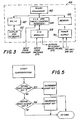
- coast compensation mode of operation of the present invention is illustrated in the flow chart of Figure 5.
- Coast is the number of revolutions made by auger 18 after the signal to brake is given to clutch-brake 40.
- the purpose of coast compensation is to correct for variable and normally uncontrollable coast.
- auger 18 rotates the number of revolutions calculated by microprocessor 60 during the trial fill mode to dispense the target weight.
- microprocessor 60 determines that the auger 18 has rotated the required number of revolutions, auguer 18 is braked by clutch-brake 40. Auger 18 continues to turn after braking as it coasts to a complete stop.
- the actual number of turns, from start to complete stop, is generated as described above by shaft encoder assembly 26 and fed to microprocessor 60.
- Microprocessor 60 compares the actual number of turns with the set number of turns calculated during trial fill for the particular product. If the actual number of turns measured by shaft encoder assembly 26 equals the set number of turns, no change is made to the set number of turns.
- the microprocessor will decrement the true set number of turns to decrease the actual number of turns in succeeding fill cycles. If the actual number of turns is less than the set number of turns, indicating a decrease in the amount of coast, the microprocessor will increment the true set number of turns to increase the actual number of turns in succeeding fill cycles.
- the true set number of turns is changed preferably by 1/lOOth of a revolution on each succeeding cycle regardless of the amount of coast. This is done in order to prevent hunting. However, it is understood that the true set number of turns may be incremented or decremented by any number of revolutions or fractions of a revolution on each succeeding cycle without departing from the present invention.
- the coast compensation mode of operation may be used separately or in conjunction with the trial fill mode of operation. That is, microprocessor 60 determines the amount of coast during the trial fill cycle and takes this into account when it sets the set number of turns. It may be assumed that the coast measured during the trial fill cycle will be reasonably close to the coast of succeeding fill cycles. By measuring the coast during the trial fill cycle and subtracting it from the calculated number of turns, the set number of turns will more accurately approximate the actual number of turns in succeeding fill cycles. Therefore, the true set point is the set number of turns minus the coast.
- the microprocessor calculates the amount of coast from the trial fill cycle from the calculated number of turns.
- the microprocessor will set 10.00 minus 0.45, or 9.55, as the true set number of turns, so that the true set number of turns, 9.55, plus the anticipated coast of succeeding fill cycles, 0.45, will add up to 10.
- the measured coast increases to 55/100ths or 0.55.
- the actual number of turns is now 10.10.
- the true set point is then decremented by 1/100th of a revolution for each succeeding cycle, i.e. the true set point is moved back to 9.54, 9.53, etc. until the set true point is decremented to 9.45 to compensate for a coast of 0.55.
- coast compensation feature of the present invention provides a simple yet effective way of compensating for and eliminating the adverse effects of coast.
Landscapes
- Engineering & Computer Science (AREA)
- Mechanical Engineering (AREA)
- Quality & Reliability (AREA)
- Basic Packing Technique (AREA)
Abstract
Description
- The basic concept of filling containers by dispensing materials from a hopper using a rotary feed mach- anism is well-known, as for example in U.S. patents Re. 23,888 and Re. 24,079. Apparatus such as that shown in these patents can be used for volumetric filling of free-flowing and non-free-flowing granular, powdered, flaked or paste material. Typically, the feed mechanism is positioned in an opening in the bottom of a vertically- disposed conical hopper and consists of either an auger or a pump. The auger, pump rotor, or other rotational member is driven by a prime mover, such as an electric motor, through a clutch-brake mechanism which connects the driving shaft of the motor to the driven shaft of the rotational member. The clutch-brake mechanism is controlled to rotate the driven shaft for a preselected number of revolutions by a device which counts the number of revolutions. This is a relatively accurate way of volumetrically dispensing material since the amount of material dispensed by each revolution of the auger or pump can be accurately determined. For example, for each revolution of an auger of known pitch and diameter, the volume of material dispensed from its discharge end can be determined. By appropriate control, the auger can be made to run through sequential cycles of a predetermined number of turns. During each cycle, therefore, a predetermined volume of material is discharged into a container positioned by mechanised packaging devices at the discharge end of the feed mechanism. Nechanised packaging line devices for sequentially positioning containers made of paper, metal, plastics or glass are well-known.
- Since each revolution of the feed mechanism dispenses a known amount of material, it follows that the number of revolutions is a measure of the volume of material that has been-dispensed. There are two methods for determining the number of revolutions. The first method is to count the number of revolutions directly. The second method is to measure the time period over which the feed mechanism is being driven at a constant speed. In known apparatus, devices for counting the number of revolutions include counters directly linked by gearing to the output side of the clutch-brake mechanism mentioned above, and shaft encoders directly or indirectly coupled to the driven shaft which generate a given number of pulses for each complete revolution of the driven shaft. When the correct count is reached, the driven shaft is disengaged from the driving shaft and braked by the clutch-brake mechanism. Although such mechanisms are manufactured with precision and assembled with rigorous quality monitoring, in some cases inherent errors result in a repetitive accuracy of performance which is less than is desired.
- The timed method of controlling the number ofrevo- lutions is less accurate than the count method, although in certain cases the timed method of controlling the number of revolutions may yield acceptable accuracy.
- One factor which contributes to the inherent inaccuracies in the direct counting method of determining the number of shaft revolutions is what may be termed shaft "coast". It is known that, due to the inertia of a rotating shaft and practical limits on the braking system, a rotating shaft will continue to rotate for a fraction of a revolution or even several revolutions after the brake is applied before coming to a complete stop. This additional, unwanted rotation of the shaft after the brake is applied and before it comes to a complete stop is referred to as "coast". Obviously, as an auger shaft coasts beyond the desired number of turns it continues to dispense material from the hopper. This results in over-filling of the containers, with concomitant spilling, waste and loss of time and money to the packer.
- It is an object of the present invention to compensate for the coast inherent in any filling machine so that a more accurate fill is obtained.
- In addition to compensating for coast, there is another aspect to the invention. As noted above, known filling machines operate in a volumetric mode. That is, for an auger of known pitch and diameter, each revolution of the auger dispenses a given volume. However, in many instances, the material being filled into the container is ultimately sold to the consumer by weight, not volume. Thus, in order to fill a one-kilogram coffee can with one kilogram of coffee for example, the filling machine must dispense a particular volume of coffee which will have a weight of one kilogram. Obviously, the weight of the material dispensed is equal to the produce of the density of the material times the volume dispensed. Variations in density, due to factors such as temperature, humidity or other factors, will result in different weights of material for a given volume. In order for an operator to be sure that he is consistently filling containers to the proper weight, he must engage in a lengthy, time- consuming and potentially inaccurate process of finding the volume which gives him the desired weight for a particular product run. Typically, this necessitates a large number of trial cycles in which the operator fills a container with a volume which he estimates will give him the desired weight. He then weighs the container, and adjusts the volume delivered depending upon whether the weight is high or low. Depending upon theoperator's skill and the particular product and ambient conditions, this may take a large number of trials.
- It is another object of the invention to eliminate the need for a large number of trial fill cycles when setting up a filler machine and to permit the number of auger revolutions required to dispense a given weight to be determined in a single trial fill operation.
- In accordance with the invention there is provided a filler apparatus of the type having a hopper means for storing material to be dispensed by the filler, rotary feed means operatively associated with the hopper means for dispensing controlled volumes of material from a discharge opening in the hopper means into containers to be filled, said volumes being directly proportional to the time of revolution of the rotary feed means, cyclically engageable drive means for rotating the rotary feed means, and brake means for stopping the rotation of the rotary feed means after a predetermined time of revolution, characterised by
- (a) means for sensing the actual time of revolution of the rotary feed means from the time the drive means is engaged until the rotary feed means comes to a complete stop and for generating a signal indicative of the actual time of revolution; and
- (b) control means for generating said predetermined time of revolution, said predetermined time of revolution being either a preselected fixed time of a calculated time, the control means having as an input the signal indicative of the actual time of revolution, the control means further having means for entering a first weight value indicative of the weight of a volume of material delivered by the preselected fixed time of revolution of the rotary feed means, means for entering a second weight value indicative of a desired weight of material to be dispensed by the filler, means for deriving the ratio of the first weight value to the preselected fixed time of revolution of the rotary feed means, means for dividing the second weight value by said ratio to derive the calculated time, the calculated time being indicative of the time of revolution required to dispense the second weight value, means for comparing the actual time of revolution of the rotary feed means with said predetermined time of revolution, and means for incrementing said predetermined time by a preselected amount when the actual time of revolution is less than said predetermined time and decrementing said predetermined time by said preselected amount when the actual time of revolution is greater than said predetermined time, the control means being operatively associated with the drive means to rotate the rotary feed means for said predetermined time.
- Also in accordance with the invention there is provided a method of determining the time of revolution required of a rotary feed means in a filling machine of the type employing a rotary feed means and a hopper to deliver a desired weight of material into containers being filled and of compensating for continued rotation of said rotary feed means after a braking signal is applied to said rotary feed means when said rotary feed means has rotated for said time in order to have said rotary feed means come to a complete stop after a desired time of revolution, comprising the steps of:
- (a) rotating the rotary feed means for a preselected fixed time thereby to dispense a volume of material directly proportional to-the preselected fixed time;
- (b) collecting the dispensed volume of material in a container;
- (c) weighing the container and material and determining the weight of the dispensed volume of material:
- (d) determining the ratio of the preselected fixed time of revolution to said weight;
- (e) determining the product of said ratio multiplied by the desired weight of material;
- (f) rotating the rotary feed means for a time of revolution equal to said product to dispense said desired weight;
- (g) measuring the actual time of revolution of the shaft from the time it is first caused to rotate until it comes to a complete stop after braking;
- (h) comparing the actual time of revolution with the predetermined time of revolution; and
- (i) incrementing said predetermined time of revolution by a preselected amount when the actual time of revolution is less than said predetermined time and decrementing said predetermined time by said preselected amount when the actual time of revolution is greater than said predetermined time.
- For the purpose of illustrating the invention, there is shown in the drawings an embodiment which is presently preferred. It should be understood however that this invention is not limited to the precise arrangements shown.
- In the drawings:
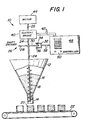
- Figure 1 illustrates a filling apparatus in accordance with the present invention in schematic form.
- Figure 2 illustrates a typical operator control panel of an apparatus in accordance with the present invention.
- Figure 3 is a block diagram of one embodiment of the control means of the apparatus of the present invention.
- Figure 4 is a flow chart illustrating the operation of the trial fill feature of the present invention.
- Figure 5 is a flow chart illustrating the operation of the coast compensation feature of the present invention.
- Referring now to the drawings, wherein like numerals indicate like elements, there is shown in Figure 1 in schematic form a
filling apparatus 10 in accordance with the present invention. Apparatus lO has ahopper 12 for storing material to be dispensed. Hopper 12 has generally the shape of an inverted cone. The bottom end of thehopper 12 terminates in a generallycylindrical outlet 14. - A
feed auger 18 is fitted within theoutlet 14 at the bottom end ofhopper 12. Rotation of theauger 18causes material 16 to be dispensed fromhopper 12 throughoutlet 14 intocontainers 20 which are positioned manually or by aconveyor 22 beneathhopper 12.Conveyor 22 may be any suitable conveyor for indexing individual containers to be filled beneathhopper outlet 14. - It should be understood that by illustrating an auger there is no intention to limit the invention to filling machines which utilise an auger.
Auger 18 could just as well be a screw rotor of a Moyno type pump such as that shown in U.S. patent Re. 24,079. However, for the purposes of illustrating the invention, reference will be made hereinafter to an auger. -
Auger 18 may be caused to rotate by means ofauger shaft 24. The lower end ofshaft 24 may be integral with or otherwise securely fastened to auger 18. The upper end ofshaft 24 is connected through clutch-brake 40 to drivingmotor 44. For the purposes of illustrating the invention, clutch-brake 40 andmotor 44 are coupled byshaft 25. Clutch-brake 40 and.motor 44 may be any conventional motor and clutch brake. Such devices are well-known and widely used in the art and need not be explained here in detail. - A
shaft encoder assembly 26 is coupled to augershaft 24.Shaft encoder assembly 26 may be an electro- optic shaft encoder such as that shown in U.S. patent 3,743,140. Alternatively,shaft encoder 26 may be any type of shaft encoder which generates signals indicative of the rotation ofauger shaft 24. In the particular embodiment illustrated in Figure 1,shaft encoder 26 consists of a disc 28 which is coupled toshaft 24 so as to rotate with it. The function of disc 28 is to act as a light chopper. For this purpose, it is provided with a plurality of slots, lines or holes 30 which are evenly spaced about its periphery. The number of slots, lines or holes 30 can be varied. However, for convenience the preferred embodiment may have 100 slots, thereby providing a number which is easily divisible to indicate a complete revolution ofshaft 24 and hence ofauger 18. Abracket 32 supports alight source 34.Light source 34 may be the filament of an incandescent lamp or a light emitting diode which generates a constant light output.Bracket 32 also supports aphotodetector 36, such as a phototransistor or the like, which is sensitive to the light energy generated by thelight source 34. - The
light source 34 and thephotodetector 36 are positioned by thebracket 32 in opposing relation adjacent to the peripheral edge of the disc 28. Thus, light energy emitted by thelight source 34 must pass through theslots 30 and the disc 28 in order to be detected by thephotodetector 36. As a result, the output of thephotodetector 36 will be a series of discrete electrical pulses whose frequency will depend upon the speed at which theshaft 24 is rotating. Likewise, the number of pulses generated in a given interval will indicate the extent to whichshaft 24, and hence auger 18, has revolved in that interval. - The pulses generated by
shaft encoder assembly 26 are fed to acontroller 48 viawires 38. Similarly, clutch-brake 40 is connected tocontroller 48 bywires 42.Controller 48, which will be described in greater detail hereinafter, receives the pulses generated byshaft encoder assembly 26, processes them in a manner to be described and generates control signals which control the operation of clutch-brake 40.Controller 48 is provided with a control/display panel 50 which may display machine status and other information to an operator, and by means of which an operator may provide various inputs tocontroller 48. - Control/
display panel 50 is shown in greater detail in Figure 2. Control/display panel 50 has adisplay section 52, which may be an LED display or liquid crystal display, or any other display suitable for displaying alphanumeric information to an operator.Display 52 may serve to display machine status, verify inputs entered by an operator, or display instructions to an operator to "prompt", or assist, the operator in providing necessary inputs or aid the operator in trouble shooting. -
Adjacent display section 52 is an operator- actuated keyboard ofpush button assembly 54. This may be used by an operator to enter commands to the machine, enter data requested by thecontroller 48, and otherwise permit the operator to communicate withcontroller 48.Control panel 50 may also include 'start' and 'stop'buttons -
Controller 48 is illustrated in greater detail in block diagram form in Figure 3. The heart ofcontroller 48 is amicroprocessor 60, which can be programmed to monitor and direct any number of machine functions. The operation ofmicroprocessor 60 is synchronised with the remainder of the machine by input via versatile interface adapter (V.I.A.) and timer/counter interface 64. Operator inputs may be entered intomicroprocessor 60 via asynchronous control interface assembly (A.C.I.A.) 62, which translates operator-entered inputs fromkeyboard assembly 52 into a form usable bymicroprocessor 60. Likewise, A.C.I.A. 62 converts prompts and other messages generated bymicroprocessor 60 into operator-readable form for display bydisplay section 52. Themicroprocessor 60 also receives inputs from other portions of theapparatus 10, such as the pulses generated byshaft encoder assembly 26, and generates control outputs to clutch-brake 40. Encoder pulses go directly into the V.I.A. 64. Other inputs and outputs are coupled tomicroprocessor 60 by means of I/O module 68.Controller 48 also includes amemory 66 which may be used to store data, commands and other information required by themicroprocessor 60 or the operator to carry out various machine functions.Power supply 70 may be any conventional power supply and converts input power in the form of 120 V ac or 240 V ac into a dc voltage suitable for the controller electronics. - The general way in which
controller 48 operates in the trial fill mode and the coast compensation mode in accordance with the present invention will now be described. It will be understood that the particular details of the programming ofmicroprocessor 60 to carry out the steps of the present invention are not crucial to the present invention. Thus,microprocessor 60 andcontroller 48 may be arranged in a variety of ways to carry out the steps of the present invention. - The operation of the trial fill mode of the filler of the present invention is illustrated in the flow chart in Figure 4. To place the filler in the trial fill mode, the operator presses a "Trial Fill" button which is provided on
keyboard 54. This signalsmicroprocessor 60 to recall frommemory 66 the instructions for carrying out the trial fill mode. When thefiller 10 is placed in the trial fill mode,microprocessor 60 generates a display which indicates that the filler is in the trial fill mode and also displays a prompt message to the operator viadisplay panel 52. The prompt message to the operator requests him to enter a number of auger shaft revolutions for the trial fill. By means of the numerical keys onkeyboard 54, the operator then enters a number of turns, which is generally less than the number of turns which the operator estimates is required to fill the container. Themicroprocessor 60 may also be programmed to drive the auger shaft for a predetermined number of revolutions in default of the operator entering a number. That is, if the operator fails to enter a number of revolutions in response to the prompt message, the microprocessor will enter a number for him. - Once the number of revolutions for the trial fill has been selected by either the operator or micro-
processor 60,microprocessor 60 generates the prompt command "Press Start Fill", prompting the operator to depress the "Start Fill" key on thecontroller keyboard 54. The operator then initiates the trial fill cycle by depressing the "Start Fill" key. - When the "Start Fill" key is depressed, the clutch-
brake 40 is activated, andauger shaft 24 begins to rotate. Asshaft 24 rotates,shaft encoder assembly 26 generates a series of pulses as described above. These pulses are counted inmicroprocessor 60, and when the number of pulses counted indicates that theshaft 24 has rotated the preselected number of turns, clutch-brake 40 is reset to brakeshaft 24.Microprocessor 60 then checks to make sure thatshaft 24 has come to a complete stop. - Once
shaft 24 has come to a complete stop,microprocessor 60 computes the amount of coast of the shaft during the trial fill cycle. As will be explained in greater detail below, coast is simply the difference between the actual number of turns as indicated by the shaft encoder assembly minus the preselected number of turns entered by the operator or selected by the microprocessor. The coast computed bymicroprocessor 60 is taken into account when calculating the number of turns required to dispense the desired weight and is also used in the coast compensation mode of operation to be explained in detail below. - After
microprocessor 60 has computed the coast of the trial fill cycle, it generates a prompt requesting the operator to enter the sample weight, i.e. the weight of the material discharged during the trial fill cycle. The operator obtains the weight of the material, for example by means of a scale, and enters the sample weight by means of the numeric keys onkeyboard 54.Microprocessor 60 then prompts the operator to enter the target weight, that is, the weight desired to be filled into each container. The operator enters the target weight by means ofkeyboard 54 in the same manner as he enters the preselected number of turns and sample weight. After the sample weight and target weight have been entered,microprocessor 60 computes the number of turns ofauger shaft 24 required to deliver the target weight into the container. This number of turns computed by the microprocessor is then used by the microprocessor as a set point for each fill cycle until the machine is reset for a different product or a different target weight. - An example will make the operation of the trial fill feature clear. Assume that five kilograms of sugar are to be dispensed into containers. Therefore, the target weight, or WT' is five kilograms. For the trial fill cycle, the operator selects a number of revolutions, in this example let us say two revolutions of the auger. He enters this into the controller via
keyboard 54, and the filler dispenses material by rotating the auger shaft two turns (plus coast). The operator then weighs the sugar dispensed by those two turns of the auger revolution and determines that the weight of sugar dispensed is one kilogram. This is the sample weight, or WS. Knowing the sample weight and the number of revolutions of the auger which dispensed the sample weight, the weight of material dispensed per auger revolution may be determined. Thus, in this example, WS/RA equals one half kilogram per revolution, where RA represents the number of auger revolutions selected by the operator for the trial fill cycle plus the amount of coast. Once this ratio is known, it is possible to calculate the number of revolutions required to give any desired weight. The target number of revolutions, RT, required to deliver a target weight, WT, is equal to the target weight divided by the ratio Ws/RA. In this example, the target weight is five kilograms and the ratio Ws/RA is one half. Thus, the target number of revolutions, RT, required to dispense five kilograms of sugar is equal to ten. - Itwill be appreciated that the trial fill mode of operation of the present invention provides a rapid, accurate and extremely simple method of determining the actual number of revolutions required to dispense a target weight. Only one fill is required, eliminating the need for repeated fill cycles required by the trial and error method necessary with current fillers.
-
Microprocessor 60 may also be programmed to operate in the timed auger rotation mode instead of the count mode of operation. In such a case, the trial fill mode would be the same as that for the count mode of operation, except thatmicroprocessor 60 would calculate the amount oftime auger 18 must rotate in order to dispense the target weight along with the number of revolutions. - The coast compensation mode of operation of the present invention is illustrated in the flow chart of Figure 5. Coast is the number of revolutions made by
auger 18 after the signal to brake is given to clutch-brake 40. The purpose of coast compensation is to correct for variable and normally uncontrollable coast. - For each individual fill cycle,
auger 18 rotates the number of revolutions calculated bymicroprocessor 60 during the trial fill mode to dispense the target weight. Whenmicroprocessor 60 determines that theauger 18 has rotated the required number of revolutions,auguer 18 is braked by clutch-brake 40.Auger 18 continues to turn after braking as it coasts to a complete stop. The actual number of turns, from start to complete stop, is generated as described above byshaft encoder assembly 26 and fed tomicroprocessor 60.Microprocessor 60 compares the actual number of turns with the set number of turns calculated during trial fill for the particular product. If the actual number of turns measured byshaft encoder assembly 26 equals the set number of turns, no change is made to the set number of turns. However, if the actual number of turns is greater than the set number of turns, indicating an increase in coast, the microprocessor will decrement the true set number of turns to decrease the actual number of turns in succeeding fill cycles. If the actual number of turns is less than the set number of turns, indicating a decrease in the amount of coast, the microprocessor will increment the true set number of turns to increase the actual number of turns in succeeding fill cycles. The true set number of turns is changed preferably by 1/lOOth of a revolution on each succeeding cycle regardless of the amount of coast. This is done in order to prevent hunting. However, it is understood that the true set number of turns may be incremented or decremented by any number of revolutions or fractions of a revolution on each succeeding cycle without departing from the present invention. - The coast compensation mode of operation may be used separately or in conjunction with the trial fill mode of operation. That is,
microprocessor 60 determines the amount of coast during the trial fill cycle and takes this into account when it sets the set number of turns. It may be assumed that the coast measured during the trial fill cycle will be reasonably close to the coast of succeeding fill cycles. By measuring the coast during the trial fill cycle and subtracting it from the calculated number of turns, the set number of turns will more accurately approximate the actual number of turns in succeeding fill cycles. Therefore, the true set point is the set number of turns minus the coast. - As an example, assume that during the trial fill example previously discussed, 45/100ths of a revolution of coast were measured. Since the microprocessor calculated that ten turns were required during the trial fill cycle, instead of using ten as the true set of turns, the microprocessor subtracts the amount of coast from the trial fill cycle from the calculated number of turns. Thus, the microprocessor will set 10.00 minus 0.45, or 9.55, as the true set number of turns, so that the true set number of turns, 9.55, plus the anticipated coast of succeeding fill cycles, 0.45, will add up to 10. Assume that several fill cycles later the measured coast increases to 55/100ths or 0.55. The actual number of turns is now 10.10. The true set point is then decremented by 1/100th of a revolution for each succeeding cycle, i.e. the true set point is moved back to 9.54, 9.53, etc. until the set true point is decremented to 9.45 to compensate for a coast of 0.55.
- It will be appreciated that the coast compensation feature of the present invention provides a simple yet effective way of compensating for and eliminating the adverse effects of coast.
Claims (8)
Priority Applications (1)
| Application Number | Priority Date | Filing Date | Title |
|---|---|---|---|
| AT84303474T ATE31174T1 (en) | 1983-10-05 | 1984-05-22 | CONTROL DEVICE FOR AND METHOD OF DRIVE FOR AN AUTOMATIC FILLING MACHINE. |
Applications Claiming Priority (2)
| Application Number | Priority Date | Filing Date | Title |
|---|---|---|---|
| US06/539,194 US4582097A (en) | 1983-10-05 | 1983-10-05 | Control apparatus and method for automatic filling machine |
| US539194 | 1983-10-05 |
Publications (3)
| Publication Number | Publication Date |
|---|---|
| EP0125932A2 true EP0125932A2 (en) | 1984-11-21 |
| EP0125932A3 EP0125932A3 (en) | 1986-02-05 |
| EP0125932B1 EP0125932B1 (en) | 1987-12-02 |
Family
ID=24150199
Family Applications (1)
| Application Number | Title | Priority Date | Filing Date |
|---|---|---|---|
| EP84303474A Expired EP0125932B1 (en) | 1983-10-05 | 1984-05-22 | Control apparatus for and method of operating automatic filling machine |
Country Status (8)
| Country | Link |
|---|---|
| US (1) | US4582097A (en) |
| EP (1) | EP0125932B1 (en) |
| JP (1) | JPS6077801A (en) |
| AT (1) | ATE31174T1 (en) |
| AU (1) | AU579821B2 (en) |
| CA (1) | CA1227855A (en) |
| DE (2) | DE125932T1 (en) |
| ES (1) | ES533014A0 (en) |
Cited By (3)
| Publication number | Priority date | Publication date | Assignee | Title |
|---|---|---|---|---|
| DE3640520A1 (en) * | 1986-11-27 | 1988-06-09 | Rovema Gmbh | Process for the metering and packaging of pourable materials and packaging machine for carrying out the process |
| EP0270814A2 (en) * | 1986-12-09 | 1988-06-15 | Societe Des Produits Nestle S.A. | Distributing and dosing device |
| FR2978064A1 (en) * | 2011-07-18 | 2013-01-25 | Interlab | METHOD AND DEVICE FOR GRAVIMETRIC DISTRIBUTION AND SOLUTION SERIES. |
Families Citing this family (23)
| Publication number | Priority date | Publication date | Assignee | Title |
|---|---|---|---|---|
| US4648430A (en) * | 1984-06-22 | 1987-03-10 | Baxter Travenol Laboratories, Inc. | Device and method for collecting a desired weight amount of a material |
| BE903728A (en) * | 1985-11-28 | 1986-03-14 | Meulenbeke Pierre Van | Mechanism to fill mould cavities with chocolate, cream, fondant etc. - has container with nozzles above cavities and fed by pump controlled to fill all cavities and then momentarily reverse to prevent spillage |
| US4696329A (en) * | 1986-06-09 | 1987-09-29 | Mateer Burt Co., Inc. | Feedback control for automatic filling machine |
| JPH07100112B2 (en) * | 1987-03-14 | 1995-11-01 | 株式会社東芝 | Detergent supply device for washing machines |
| US5623976A (en) * | 1994-01-24 | 1997-04-29 | Benjamin Moore & Co. | Method and apparatus for supplying containers |
| SE9400462D0 (en) * | 1994-02-11 | 1994-02-11 | Astra Ab | Filling device |
| US5485066A (en) * | 1994-04-15 | 1996-01-16 | Savannah Foods And Industries | Variable speed centrifugal drive control for sugar refining machines and the like |
| DE19619748A1 (en) * | 1996-05-15 | 1997-11-20 | Krupp Foerdertechnik Gmbh | Filling bulk material container, especially for vehicle with specified filling volume |
| DE19715579C2 (en) * | 1997-04-15 | 2002-09-26 | Bosch Gmbh Robert | Process for dosing a bulk quantity |
| US7014640B2 (en) * | 2003-03-28 | 2006-03-21 | Depuy Products, Inc. | Bone graft delivery device and method of use |
| FR2866705B1 (en) * | 2004-02-25 | 2006-10-20 | Valery Belz | DEVICE FOR DOSING A LIQUID INSIDE A CONTAINER AND ASSOCIATED METHOD |
| DE102005024079A1 (en) * | 2004-05-25 | 2006-01-19 | Invensys Systems, Inc., Foxboro | Filling system operating method for automation professionals, involves determining total amount of fluid that has flowed through conduit plus run-off amount and comparing to target amount to initiate closure of valve |
| FR2885032B1 (en) * | 2005-04-29 | 2007-07-27 | Sdgi Holdings Inc | KIT AND INSTRUMENTATION FOR EXECUTING A SPINAL IMPLANTATION PROCEDURE |
| US7527078B2 (en) * | 2005-10-13 | 2009-05-05 | Fluid Management, Llc | Apparatuses for dispensing materials volumetrically and gravimetrically based on a stored formula and methods of dispensing formulas using the same |
| DE102009046288A1 (en) * | 2009-11-02 | 2011-05-05 | Robert Bosch Gmbh | Device for the metered filling of bulk material |
| EP2551205A4 (en) * | 2010-03-23 | 2013-11-13 | Cretem Co Ltd | Automatic free-form tablet dispenser for medication packaging device and method for dispensing tablets thereby |
| CN103596860B (en) | 2011-05-29 | 2016-04-20 | 戈拉工业公司 | For controlling valve system, the system of Distribution of materials, and method |
| CN102837836B (en) * | 2012-09-18 | 2014-08-13 | 无锡力马化工机械有限公司 | Full-automatic quantitative material taking device |
| CN103832841A (en) * | 2014-02-25 | 2014-06-04 | 任定胜 | Automatic feeder |
| CN104973276A (en) * | 2014-04-01 | 2015-10-14 | 张胤涵 | Automatic packaging equipment |
| CN104340383A (en) * | 2014-10-09 | 2015-02-11 | 天津市金桥焊材集团有限公司 | Automatic taking device for medicine powder |
| CN104494862A (en) * | 2014-11-30 | 2015-04-08 | 韦峰 | Powder quantitative equipment and mounting method thereof |
| CN105905327A (en) * | 2016-06-20 | 2016-08-31 | 无锡鼎茂机械制造有限公司 | Traditional Chinese medicinal material packaging machine |
Citations (3)
| Publication number | Priority date | Publication date | Assignee | Title |
|---|---|---|---|---|
| US3073400A (en) * | 1959-07-16 | 1963-01-15 | Fr Hesser Maschinenfabrik Ag F | Volumetric filling machine |
| US3743140A (en) * | 1970-12-21 | 1973-07-03 | Diehl Mateer G Co | Filler apparatus with hopper and rotary feed mechanism for dispensing controlled volumes of materials |
| CH595241A5 (en) * | 1976-10-05 | 1978-02-15 | Sig Schweiz Industrieges |
Family Cites Families (6)
| Publication number | Priority date | Publication date | Assignee | Title |
|---|---|---|---|---|
| US23888A (en) * | 1859-05-10 | Improvement in machines for separating stones | ||
| US24079A (en) * | 1859-05-17 | evarts | ||
| US3744310A (en) * | 1971-10-29 | 1973-07-10 | Ibm | Positioning dual record cards in a composite punch/read station in coordination with keying of source information taken from portions of the card which may be obstructed by station components |
| US4331262A (en) * | 1978-04-07 | 1982-05-25 | New Brunswick Scientific Co., Inc. | Calibratable automatic fluid dispenser |
| US4358721A (en) * | 1980-05-20 | 1982-11-09 | Abex Corporation | Bridge positioning device |
| JPS5749089A (en) * | 1980-09-05 | 1982-03-20 | Tokico Ltd | Liquid supply system |
-
1983
- 1983-10-05 US US06/539,194 patent/US4582097A/en not_active Expired - Lifetime
-
1984
- 1984-05-22 DE DE198484303474T patent/DE125932T1/en active Pending
- 1984-05-22 EP EP84303474A patent/EP0125932B1/en not_active Expired
- 1984-05-22 AT AT84303474T patent/ATE31174T1/en not_active IP Right Cessation
- 1984-05-22 DE DE8484303474T patent/DE3467878D1/en not_active Expired
- 1984-05-23 CA CA000454907A patent/CA1227855A/en not_active Expired
- 1984-05-25 AU AU28715/84A patent/AU579821B2/en not_active Ceased
- 1984-05-31 ES ES533014A patent/ES533014A0/en active Granted
- 1984-06-01 JP JP59111091A patent/JPS6077801A/en active Pending
Patent Citations (3)
| Publication number | Priority date | Publication date | Assignee | Title |
|---|---|---|---|---|
| US3073400A (en) * | 1959-07-16 | 1963-01-15 | Fr Hesser Maschinenfabrik Ag F | Volumetric filling machine |
| US3743140A (en) * | 1970-12-21 | 1973-07-03 | Diehl Mateer G Co | Filler apparatus with hopper and rotary feed mechanism for dispensing controlled volumes of materials |
| CH595241A5 (en) * | 1976-10-05 | 1978-02-15 | Sig Schweiz Industrieges |
Cited By (5)
| Publication number | Priority date | Publication date | Assignee | Title |
|---|---|---|---|---|
| DE3640520A1 (en) * | 1986-11-27 | 1988-06-09 | Rovema Gmbh | Process for the metering and packaging of pourable materials and packaging machine for carrying out the process |
| EP0270814A2 (en) * | 1986-12-09 | 1988-06-15 | Societe Des Produits Nestle S.A. | Distributing and dosing device |
| CH670034A5 (en) * | 1986-12-09 | 1989-05-12 | Nestle Sa | |
| EP0270814A3 (en) * | 1986-12-09 | 1989-11-23 | Societe Des Produits Nestle S.A. | Distributing and dosing device |
| FR2978064A1 (en) * | 2011-07-18 | 2013-01-25 | Interlab | METHOD AND DEVICE FOR GRAVIMETRIC DISTRIBUTION AND SOLUTION SERIES. |
Also Published As
| Publication number | Publication date |
|---|---|
| ATE31174T1 (en) | 1987-12-15 |
| DE125932T1 (en) | 1985-08-14 |
| EP0125932B1 (en) | 1987-12-02 |
| EP0125932A3 (en) | 1986-02-05 |
| ES8507062A1 (en) | 1985-08-16 |
| DE3467878D1 (en) | 1988-01-14 |
| US4582097A (en) | 1986-04-15 |
| AU2871584A (en) | 1985-04-18 |
| ES533014A0 (en) | 1985-08-16 |
| JPS6077801A (en) | 1985-05-02 |
| AU579821B2 (en) | 1988-12-15 |
| CA1227855A (en) | 1987-10-06 |
Similar Documents
| Publication | Publication Date | Title |
|---|---|---|
| EP0125932B1 (en) | Control apparatus for and method of operating automatic filling machine | |
| US4696329A (en) | Feedback control for automatic filling machine | |
| US4381545A (en) | Control means and method for powder bagging | |
| US3743140A (en) | Filler apparatus with hopper and rotary feed mechanism for dispensing controlled volumes of materials | |
| US4320855A (en) | Weigh feeding apparatus | |
| US4370779A (en) | Method and apparatus for intermittently dispensing flowable foodstuff | |
| USRE32101E (en) | Weigh feeding apparatus | |
| US4111272A (en) | Weigh feeding apparatus | |
| US4843579A (en) | Weighing and filling method and apparatus | |
| US4534428A (en) | Vibratory feeder control for a weighing system | |
| US4407108A (en) | Apparatus and method for powder bagging | |
| US4225930A (en) | Planter population monitor | |
| US3679010A (en) | Digitally controlled mass flow feeder and weight integrator | |
| US4563361A (en) | Method of dosing emulsifiers in chocolate mass | |
| USRE32102E (en) | Weigh feeding apparatus | |
| US4522274A (en) | Combinatorial weighing method | |
| US3498395A (en) | Automatic feed control for high speed weighing | |
| WO2002053348A1 (en) | A system for feeding portions of material to an injection molding machine | |
| US4458827A (en) | Method to meter adhesive for adhesively coating chips, fibers and the like for the manufacture of composite panels, as well as apparatus to carry out the method | |
| WO2019178295A1 (en) | Systems and methods for performing automated fastener selection | |
| US4234102A (en) | Apparatus for measuring and dispensing constant weight portions of material | |
| JPS5948329B2 (en) | Device for controlling and adjusting the distributed weight of bulk material in a rotating weighing head | |
| JPH1099998A (en) | Tablet making machine | |
| CA2030831A1 (en) | Apparatus for dispensing particulate materials | |
| WO1990000384A1 (en) | Method and plant for measuring and portioning of fodder |
Legal Events
| Date | Code | Title | Description |
|---|---|---|---|
| PUAI | Public reference made under article 153(3) epc to a published international application that has entered the european phase |
Free format text: ORIGINAL CODE: 0009012 |
|
| AK | Designated contracting states |
Designated state(s): AT BE CH DE FR GB IT LI LU NL SE |
|
| ITCL | It: translation for ep claims filed |
Representative=s name: JACOBACCI CASETTA & PERANI S.P.A. |
|
| EL | Fr: translation of claims filed | ||
| TCNL | Nl: translation of patent claims filed | ||
| TCAT | At: translation of patent claims filed | ||
| RAP1 | Party data changed (applicant data changed or rights of an application transferred) |
Owner name: MATEER-BURT COMPANY, INC. |
|
| DET | De: translation of patent claims | ||
| PUAL | Search report despatched |
Free format text: ORIGINAL CODE: 0009013 |
|
| AK | Designated contracting states |
Designated state(s): AT BE CH DE FR GB IT LI LU NL SE |
|
| 17P | Request for examination filed |
Effective date: 19860519 |
|
| 17Q | First examination report despatched |
Effective date: 19861105 |
|
| GRAA | (expected) grant |
Free format text: ORIGINAL CODE: 0009210 |
|
| AK | Designated contracting states |
Kind code of ref document: B1 Designated state(s): AT BE CH DE FR GB IT LI LU NL SE |
|
| PG25 | Lapsed in a contracting state [announced via postgrant information from national office to epo] |
Ref country code: NL Effective date: 19871202 Ref country code: LI Effective date: 19871202 Ref country code: IT Free format text: LAPSE BECAUSE OF FAILURE TO SUBMIT A TRANSLATION OF THE DESCRIPTION OR TO PAY THE FEE WITHIN THE PRESCRIBED TIME-LIMIT;WARNING: LAPSES OF ITALIAN PATENTS WITH EFFECTIVE DATE BEFORE 2007 MAY HAVE OCCURRED AT ANY TIME BEFORE 2007. THE CORRECT EFFECTIVE DATE MAY BE DIFFERENT FROM THE ONE RECORDED. Effective date: 19871202 Ref country code: FR Free format text: THE PATENT HAS BEEN ANNULLED BY A DECISION OF A NATIONAL AUTHORITY Effective date: 19871202 Ref country code: CH Effective date: 19871202 Ref country code: BE Effective date: 19871202 Ref country code: AT Effective date: 19871202 |
|
| REF | Corresponds to: |
Ref document number: 31174 Country of ref document: AT Date of ref document: 19871215 Kind code of ref document: T |
|
| PG25 | Lapsed in a contracting state [announced via postgrant information from national office to epo] |
Ref country code: SE Effective date: 19871231 |
|
| REF | Corresponds to: |
Ref document number: 3467878 Country of ref document: DE Date of ref document: 19880114 |
|
| REG | Reference to a national code |
Ref country code: CH Ref legal event code: PL |
|
| EN | Fr: translation not filed | ||
| NLV1 | Nl: lapsed or annulled due to failure to fulfill the requirements of art. 29p and 29m of the patents act | ||
| PG25 | Lapsed in a contracting state [announced via postgrant information from national office to epo] |
Ref country code: LU Free format text: LAPSE BECAUSE OF NON-PAYMENT OF DUE FEES Effective date: 19880531 |
|
| PLBE | No opposition filed within time limit |
Free format text: ORIGINAL CODE: 0009261 |
|
| STAA | Information on the status of an ep patent application or granted ep patent |
Free format text: STATUS: NO OPPOSITION FILED WITHIN TIME LIMIT |
|
| 26N | No opposition filed | ||
| PGFP | Annual fee paid to national office [announced via postgrant information from national office to epo] |
Ref country code: DE Payment date: 20010530 Year of fee payment: 18 |
|
| REG | Reference to a national code |
Ref country code: GB Ref legal event code: IF02 |
|
| PGFP | Annual fee paid to national office [announced via postgrant information from national office to epo] |
Ref country code: GB Payment date: 20021108 Year of fee payment: 19 |
|
| PG25 | Lapsed in a contracting state [announced via postgrant information from national office to epo] |
Ref country code: DE Free format text: LAPSE BECAUSE OF NON-PAYMENT OF DUE FEES Effective date: 20021203 |
|
| PG25 | Lapsed in a contracting state [announced via postgrant information from national office to epo] |
Ref country code: GB Free format text: LAPSE BECAUSE OF NON-PAYMENT OF DUE FEES Effective date: 20030522 |
|
| GBPC | Gb: european patent ceased through non-payment of renewal fee |
Effective date: 20030522 |