EP0124418A2 - Elektrische Servolenkung mit Zahnstange für Kraftfahrzeuge - Google Patents
Elektrische Servolenkung mit Zahnstange für Kraftfahrzeuge Download PDFInfo
- Publication number
- EP0124418A2 EP0124418A2 EP84400777A EP84400777A EP0124418A2 EP 0124418 A2 EP0124418 A2 EP 0124418A2 EP 84400777 A EP84400777 A EP 84400777A EP 84400777 A EP84400777 A EP 84400777A EP 0124418 A2 EP0124418 A2 EP 0124418A2
- Authority
- EP
- European Patent Office
- Prior art keywords
- pinion
- mechanism according
- rack
- rack structure
- housing
- Prior art date
- Legal status (The legal status is an assumption and is not a legal conclusion. Google has not performed a legal analysis and makes no representation as to the accuracy of the status listed.)
- Granted
Links
Images

Classifications
-
- B—PERFORMING OPERATIONS; TRANSPORTING
- B62—LAND VEHICLES FOR TRAVELLING OTHERWISE THAN ON RAILS
- B62D—MOTOR VEHICLES; TRAILERS
- B62D3/00—Steering gears
- B62D3/02—Steering gears mechanical
- B62D3/12—Steering gears mechanical of rack-and-pinion type
-
- B—PERFORMING OPERATIONS; TRANSPORTING
- B62—LAND VEHICLES FOR TRAVELLING OTHERWISE THAN ON RAILS
- B62D—MOTOR VEHICLES; TRAILERS
- B62D5/00—Power-assisted or power-driven steering
- B62D5/04—Power-assisted or power-driven steering electrical, e.g. using an electric servo-motor connected to, or forming part of, the steering gear
- B62D5/0403—Power-assisted or power-driven steering electrical, e.g. using an electric servo-motor connected to, or forming part of, the steering gear characterised by constructional features, e.g. common housing for motor and gear box
-
- B—PERFORMING OPERATIONS; TRANSPORTING
- B62—LAND VEHICLES FOR TRAVELLING OTHERWISE THAN ON RAILS
- B62D—MOTOR VEHICLES; TRAILERS
- B62D5/00—Power-assisted or power-driven steering
- B62D5/04—Power-assisted or power-driven steering electrical, e.g. using an electric servo-motor connected to, or forming part of, the steering gear
- B62D5/0421—Electric motor acting on or near steering gear
- B62D5/0424—Electric motor acting on or near steering gear the axes of motor and final driven element of steering gear, e.g. rack, being parallel
- B62D5/0427—Electric motor acting on or near steering gear the axes of motor and final driven element of steering gear, e.g. rack, being parallel the axes being coaxial
-
- B—PERFORMING OPERATIONS; TRANSPORTING
- B62—LAND VEHICLES FOR TRAVELLING OTHERWISE THAN ON RAILS
- B62D—MOTOR VEHICLES; TRAILERS
- B62D5/00—Power-assisted or power-driven steering
- B62D5/04—Power-assisted or power-driven steering electrical, e.g. using an electric servo-motor connected to, or forming part of, the steering gear
- B62D5/0442—Conversion of rotational into longitudinal movement
- B62D5/0445—Screw drives
- B62D5/0448—Ball nuts
Definitions
- the present invention relates to electric power steering mechanisms for motor vehicles and, more particularly, an electric power steering mechanism of the rack and pinion type, comprising an actuation chain comprising a rotary input member, intended to be connected to a steering wheel, integral with a pinion meshing, in a steering box, with a rack structure intended to be connected to a steering system for steering the vehicle, an electric assistance motor coupled to the winery - No actuation, and a sensor means coupled to the input member for selectively controlling the electric motor according to the rotation of the input member.
- an electric power steering mechanism of the rack and pinion type comprising an actuation chain comprising a rotary input member, intended to be connected to a steering wheel, integral with a pinion meshing, in a steering box, with a rack structure intended to be connected to a steering system for steering the vehicle, an electric assistance motor coupled to the winery - No actuation, and a sensor means coupled to the input member for selectively controlling the electric motor according to the rotation of the input member.
- the object of the present invention is to propose an electric power steering mechanism of light, compact structure, requiring only a reduced number of constituent elements, low manufacturing costs, having low inertia, and having the form of a unitary assembly capable of being easily installed on any type of vehicle, without causing any particular structural modifications to the vehicle - or to its steering wheel orientation system.
- the electric motor comprises a stator mounted in the steering box and a rotor arranged coaxially around a cylindrical part of the rack structure provided with helical grooves and forming a screw of a ball circuit mechanism by cooperating with a structure of nut with helical grooves integral with the rotor.
- the electric assistance motor is integrated in the steering box and acts directly on the output member of the latter, with consequently optimum efficiency and reduced electrical consumption.
- the helical grooves for circulation of balls of the rack structure form the means for meshing the latter with the pinion of the input member, typically a globoid pinion with Novikof profile, the rack structure advantageously being produced by stamping a hollow tube.
- the electric power steering mechanism represented in FIGS. 1 to 5 comprises a steering box, generally designated by 1 reference 10, produced for example in foundry and comprising a main body part 11 of generally cylindrical extended appearance, of a side, by a tubular part 12 and closed, opposite to the latter, by an annular cover 13.
- the housing 10 forms a transverse tubular housing 14 in which is pivotally mounted a drive assembly consisting of a pinion 20 and an input shaft element 21 intended to be connected to the steering wheel of a vehicle.
- an electric motor generally designated by the reference 30 and comprising a cylindrical stator 31 mounted in the body and a coaxial assembly of a rotor 32 and a tubular nut structure central 33, this inner rotating assembly being rotatably supported in the housing 10 and the cover 13 by bearings such as 34.
- a rack structure generally designated by the reference 40, extends coaxially in the tubular extension 12 of the housing 10 and the rotating assembly 32-33 and extends on either side of the housing 10, the axially opposite ends of the rack structure 40 each being provided with an articulated connection means 50 to connecting rods 51 of a system steering wheels of the vehicle.
- the rack structure 40 is produced by stamping a hollow tube so as to have, over a major part of its length extending in the main body part 11 of the housing 10, peripheral helical grooves 41.
- the end of the rack structure 40 opposite the electric motor 30 and extending beyond, towards the outside, the tubular extension 12 of the housing 10, on the other hand has a generally cylindrical smooth peripheral wall but with a longitudinal plate 42 intended to cooperate with an elastic pusher 43 mounted transversely in a boss 44 of the end of the tubular extension 12 of the housing 10.
- the rack structure 40 can slide longitudinally in the housing 10 without, however, being able to rotate from its own axis, which is also the axis of the electric motor 30.
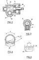
- the central nut structure33 integral with the rotor 32 has helical grooves 35 and at least one ball recirculation unit 36 (also shown in FIGS. 4 and 5) for drive balls 37 cooperating with both the internal grooves of the nut 33 and the outer grooves of the rack structure 40 so as to convert the rotational movement of the rotor 32 into a translational movement of the rack structure 40. As shown in FIGS.
- each ball recirculation unit 36 forms, on its inner surfaces, a tortuous recirculation channel of width, in longitudinal view, equal to the pitch P of the helical grooves 41 and 35, and having a length greater than said pitch P to recirculate the balls having completed a helical path on a developed angle a equal to approximately 300 °.
- the drive pinion 20 is, as can be seen in FIG. 2, a globoid pinion with Novikof profile as described for example in volume 179, n ° 30 of PROC INSTN MECH ENGRS 1964-1965 page 931 et seq., Meshing directly with the helical grooves 41 for recirculating balls of the rack structure 40.
- the transverse tubular housing 14 of the housing 10 is arranged, associated with the input shaft element 21, a sensor means or transducer 60 actuable, depending on the rotation of the input shaft 21 in either direction, for selectively controlling the electric motor 30 as a function of the direction and the amplitude of rotation of the input shaft 21.
- the sensor means 60 is a magnetostriction torque measurement sensor as described in the October 1969 edition of "Instrumentation technology", page 95 et seq.
- a seat 52 for a ball joint 53 at the end of the rod 51 is held in place by a cap 54 screwed on the externally threaded end of the rack 40.
- a sealing bellows 55 is advantageously provided at least between the cover 13 and the adjacent cap 54.
Landscapes
- Engineering & Computer Science (AREA)
- Chemical & Material Sciences (AREA)
- Combustion & Propulsion (AREA)
- Transportation (AREA)
- Mechanical Engineering (AREA)
- Power Steering Mechanism (AREA)
- Transmission Devices (AREA)
Applications Claiming Priority (2)
| Application Number | Priority Date | Filing Date | Title |
|---|---|---|---|
| ES522273A ES8403808A1 (es) | 1983-04-28 | 1983-04-28 | Mecanismo de direcion asistida electricamente para automoviles |
| ES522273 | 1983-04-28 |
Publications (3)
| Publication Number | Publication Date |
|---|---|
| EP0124418A2 true EP0124418A2 (de) | 1984-11-07 |
| EP0124418A3 EP0124418A3 (en) | 1985-06-26 |
| EP0124418B1 EP0124418B1 (de) | 1986-11-20 |
Family
ID=8485709
Family Applications (1)
| Application Number | Title | Priority Date | Filing Date |
|---|---|---|---|
| EP84400777A Expired EP0124418B1 (de) | 1983-04-28 | 1984-04-18 | Elektrische Servolenkung mit Zahnstange für Kraftfahrzeuge |
Country Status (7)
| Country | Link |
|---|---|
| US (1) | US4572314A (de) |
| EP (1) | EP0124418B1 (de) |
| JP (1) | JPS59206259A (de) |
| AU (1) | AU557855B2 (de) |
| BR (1) | BR8402046A (de) |
| DE (1) | DE3461359D1 (de) |
| ES (1) | ES8403808A1 (de) |
Cited By (10)
| Publication number | Priority date | Publication date | Assignee | Title |
|---|---|---|---|---|
| US4660671A (en) * | 1985-10-23 | 1987-04-28 | Trw Inc. | Electric steering gear |
| GB2187692A (en) * | 1986-03-12 | 1987-09-16 | Honda Motor Co Ltd | Motor-driven power steering device |
| FR2600030A1 (fr) * | 1986-04-23 | 1987-12-18 | Honda Motor Co Ltd | Systeme de direction a quatre roues directrices assistee par moteur electrique |
| GB2198098A (en) * | 1986-10-20 | 1988-06-08 | Honda Motor Co Ltd | Rear wheel steering device for vehicle with four steerable wheels |
| FR2608120A1 (fr) * | 1986-12-10 | 1988-06-17 | Renault | Mecanisme de direction assistee a commande electrique pour vehicules automobiles |
| US4918921A (en) * | 1987-10-22 | 1990-04-24 | Automotive Products Plc | Coaxial push rod and hollow screw ball nut drive for master cylinder |
| FR2657317A1 (fr) * | 1990-01-22 | 1991-07-26 | Renault | Dispositif de braquage de roues arriere pour vehicule a quatre roues directrices. |
| WO1994016931A1 (de) * | 1993-01-28 | 1994-08-04 | Zf Friedrichshafen Aktiengesellschaft | Zahnstangenlenkgetriebe, insbesondere für kraftfahrzeuge |
| EP0612651A1 (de) * | 1993-02-26 | 1994-08-31 | Siemens Aktiengesellschaft | Stellantrieb mit einem Axialgetriebe, insbesondere zum Lenken eines vier lenkbare Räder aufweisenden Fahrzeugs |
| GB2284790A (en) * | 1993-12-17 | 1995-06-21 | Honda Motor Co Ltd | Electrically operated power steering apparatus |
Families Citing this family (25)
| Publication number | Priority date | Publication date | Assignee | Title |
|---|---|---|---|---|
| AU574696B2 (en) * | 1983-07-22 | 1988-07-14 | Nippon Seiko K.K. | Power assist steering gear assembly |
| US4653602A (en) * | 1985-10-17 | 1987-03-31 | General Motors Corporation | Electric motor driven rack and pinion steering gear with take-off from axially slidable nut |
| JPS6387178U (de) * | 1986-11-27 | 1988-06-07 | ||
| JPS6483462A (en) * | 1987-09-28 | 1989-03-29 | Mazda Motor | Steering system for vehicle |
| JPS6483463A (en) * | 1987-09-28 | 1989-03-29 | Mazda Motor | Steering system for vehicle |
| JPH0195966A (ja) * | 1987-10-08 | 1989-04-14 | Mazda Motor Corp | 車両のステアリング装置 |
| JPH03121978A (ja) * | 1989-10-03 | 1991-05-23 | Isuzu Motors Ltd | 舵角制御機構 |
| JPH10278813A (ja) * | 1997-04-10 | 1998-10-20 | Koyo Seiko Co Ltd | 電動パワーステアリング装置 |
| US5988005A (en) * | 1997-07-04 | 1999-11-23 | Mitsuba Corporation | Electric power steering unit |
| JPH1134891A (ja) * | 1997-07-24 | 1999-02-09 | Mitsuba Corp | 電気式動力操舵装置 |
| JPH11198828A (ja) * | 1998-01-20 | 1999-07-27 | Mitsuba Corp | 電気式動力操舵装置 |
| JP3377763B2 (ja) | 1999-07-08 | 2003-02-17 | 本田技研工業株式会社 | 車両用フード装置 |
| JP3312692B2 (ja) | 1999-07-09 | 2002-08-12 | 本田技研工業株式会社 | 車両用フード装置 |
| JP3317441B2 (ja) | 1999-07-19 | 2002-08-26 | 本田技研工業株式会社 | 車両用フード装置 |
| US6293362B1 (en) | 1999-07-09 | 2001-09-25 | Honda Giken Kogyo Kabushiki Kaisha | Vehicle hood apparatus |
| JP3320681B2 (ja) | 1999-07-19 | 2002-09-03 | 本田技研工業株式会社 | 車両用フード装置 |
| DE29915559U1 (de) * | 1999-09-03 | 2000-01-13 | TRW Fahrwerksysteme GmbH & Co KG, 40547 Düsseldorf | Lenksystem für ein Fahrzeug |
| US6390230B1 (en) | 1999-10-06 | 2002-05-21 | Honda Giken Kogyo Kabushiki Kaisha | Electric power steering apparatus |
| JP4085878B2 (ja) * | 2003-04-25 | 2008-05-14 | 株式会社ジェイテクト | 電動パワーステアリング装置 |
| US20060278466A1 (en) * | 2005-06-13 | 2006-12-14 | Bo Cheng | Electric power steering systems |
| US8479605B2 (en) * | 2008-09-19 | 2013-07-09 | James J. Shavrnoch | Rotary-to-linear mechanism having an isolator |
| DE102008059745A1 (de) * | 2008-12-01 | 2010-06-02 | Thyssenkrupp Presta Ag | Elektromechanische Servolenkung mit Kugelgewindetrieb |
| DE102009045857A1 (de) * | 2009-10-20 | 2011-04-21 | Robert Bosch Gmbh | Verfahren zur Herstellung einer Spindel für einen Spindeltrieb, Wälzgewindetrieb mit einer solchen Spindel und Verwendung des Wälzgewindetriebs |
| US9021910B2 (en) | 2012-08-17 | 2015-05-05 | Steering Solutions Ip Holding Corporation | Ball-screw assembly isolator having compressible members |
| JP6759568B2 (ja) * | 2015-12-04 | 2020-09-23 | 株式会社ジェイテクト | ステアリング装置 |
Family Cites Families (10)
| Publication number | Priority date | Publication date | Assignee | Title |
|---|---|---|---|---|
| US1231885A (en) * | 1915-09-16 | 1917-07-03 | John O Heinze Company | Electric steering mechanism. |
| US2446393A (en) * | 1945-06-14 | 1948-08-03 | Eaton Mfg Co | Screw-threaded mechanical movement |
| BE628339A (de) * | 1962-02-14 | |||
| FR2147475A5 (de) * | 1971-07-28 | 1973-03-09 | Gemmer France | |
| GB1410956A (en) * | 1972-11-28 | 1975-10-22 | Fonda Ag | Power directing system |
| GB1590629A (en) * | 1976-09-23 | 1981-06-03 | Cam Gears Ltd | Powerassisted gear system |
| JPS5544058A (en) * | 1978-09-22 | 1980-03-28 | Kayaba Ind Co Ltd | Power steering |
| JPS55123044A (en) * | 1979-03-16 | 1980-09-22 | Jidosha Kiki Co Ltd | Rack shaft |
| JPS57195960A (en) * | 1981-05-27 | 1982-12-01 | Jidosha Kiki Co Ltd | Rack shaft and its manufacturing method |
| US4415054A (en) * | 1982-08-05 | 1983-11-15 | Trw Inc. | Steering gear |
-
1983
- 1983-04-28 ES ES522273A patent/ES8403808A1/es not_active Expired
-
1984
- 1984-04-18 DE DE8484400777T patent/DE3461359D1/de not_active Expired
- 1984-04-18 AU AU27072/84A patent/AU557855B2/en not_active Ceased
- 1984-04-18 EP EP84400777A patent/EP0124418B1/de not_active Expired
- 1984-04-23 US US06/602,835 patent/US4572314A/en not_active Expired - Fee Related
- 1984-04-27 JP JP59084211A patent/JPS59206259A/ja active Granted
- 1984-04-27 BR BR8402046A patent/BR8402046A/pt not_active IP Right Cessation
Cited By (16)
| Publication number | Priority date | Publication date | Assignee | Title |
|---|---|---|---|---|
| WO1987002631A1 (en) * | 1985-10-23 | 1987-05-07 | Trw Inc. | Electric steering gear |
| US4660671A (en) * | 1985-10-23 | 1987-04-28 | Trw Inc. | Electric steering gear |
| GB2187692A (en) * | 1986-03-12 | 1987-09-16 | Honda Motor Co Ltd | Motor-driven power steering device |
| FR2595646A1 (fr) * | 1986-03-12 | 1987-09-18 | Honda Motor Co Ltd | Direction assistee entrainee par moteur, comportant un arbre a vis separe de la cremaillere |
| GB2187692B (en) * | 1986-03-12 | 1989-11-15 | Honda Motor Co Ltd | Motor-driven power steering device |
| FR2600030A1 (fr) * | 1986-04-23 | 1987-12-18 | Honda Motor Co Ltd | Systeme de direction a quatre roues directrices assistee par moteur electrique |
| GB2198098B (en) * | 1986-10-20 | 1991-11-06 | Honda Motor Co Ltd | Rear wheel steering device for vehicle with four steerable wheels |
| GB2198098A (en) * | 1986-10-20 | 1988-06-08 | Honda Motor Co Ltd | Rear wheel steering device for vehicle with four steerable wheels |
| US5083626A (en) * | 1986-10-20 | 1992-01-28 | Honda Giken Kogyo Kabushiki Kaishi | Rear wheel steering device for vehicle with four steerable wheels |
| FR2608120A1 (fr) * | 1986-12-10 | 1988-06-17 | Renault | Mecanisme de direction assistee a commande electrique pour vehicules automobiles |
| US4918921A (en) * | 1987-10-22 | 1990-04-24 | Automotive Products Plc | Coaxial push rod and hollow screw ball nut drive for master cylinder |
| FR2657317A1 (fr) * | 1990-01-22 | 1991-07-26 | Renault | Dispositif de braquage de roues arriere pour vehicule a quatre roues directrices. |
| WO1994016931A1 (de) * | 1993-01-28 | 1994-08-04 | Zf Friedrichshafen Aktiengesellschaft | Zahnstangenlenkgetriebe, insbesondere für kraftfahrzeuge |
| EP0612651A1 (de) * | 1993-02-26 | 1994-08-31 | Siemens Aktiengesellschaft | Stellantrieb mit einem Axialgetriebe, insbesondere zum Lenken eines vier lenkbare Räder aufweisenden Fahrzeugs |
| GB2284790A (en) * | 1993-12-17 | 1995-06-21 | Honda Motor Co Ltd | Electrically operated power steering apparatus |
| GB2284790B (en) * | 1993-12-17 | 1997-11-26 | Honda Motor Co Ltd | Electrically operated power steering apparatus |
Also Published As
| Publication number | Publication date |
|---|---|
| EP0124418A3 (en) | 1985-06-26 |
| AU557855B2 (en) | 1987-01-08 |
| DE3461359D1 (en) | 1987-01-08 |
| ES522273A0 (es) | 1984-04-16 |
| EP0124418B1 (de) | 1986-11-20 |
| AU2707284A (en) | 1984-11-01 |
| US4572314A (en) | 1986-02-25 |
| JPS59206259A (ja) | 1984-11-22 |
| BR8402046A (pt) | 1984-12-11 |
| JPH0530666B2 (de) | 1993-05-10 |
| ES8403808A1 (es) | 1984-04-16 |
Similar Documents
| Publication | Publication Date | Title |
|---|---|---|
| EP0124418A2 (de) | Elektrische Servolenkung mit Zahnstange für Kraftfahrzeuge | |
| FR2853876A1 (fr) | Dispositif de direction assistee electrique | |
| FR2595646A1 (fr) | Direction assistee entrainee par moteur, comportant un arbre a vis separe de la cremaillere | |
| FR2745541A1 (fr) | Motoreducteur, notamment pour l'entrainement de bras d'essuie-glace dans un vehicule automobile | |
| EP0365377A1 (de) | Vorrichtung zum Umwandeln einer linearen Bewegung in eine oszillierende Bewegung und umgekehrt | |
| FR2801652A1 (fr) | Armature ajustable pour un systeme de deplacement a pivot d'une premiere piece d'articulation par rapport a une deuxieme piece d'articulation | |
| FR2677416A1 (fr) | Petit moteur equipe d'un mecanisme reducteur a vis. | |
| FR2602187A1 (fr) | Dispositif motorise pour siege de vehicule automobile | |
| EP0371852B1 (de) | Lenkvorrichtung für die Hinterräder eines durch vier Räder gelenkten Fahrzeuges | |
| FR2741415A1 (fr) | Reducteur compact a deux etages de reduction | |
| EP1538067B1 (de) | Kraftfahrzeugachse und Stellglied für solche Achse | |
| FR2745250A1 (fr) | Motoreducteur fixe par le couvercle | |
| FR2814297A1 (fr) | Actionneur alimente electriquement, en particulier pour commander un composant de bicyclette | |
| EP0740401A1 (de) | Getriebemotor, insbesondere für eine Kraftfahrzeugscheibenwischervorrichtung | |
| FR2727374A1 (fr) | Direction a cremaillere ou commande de direction a cremaillere assistee par un servomoteur | |
| EP0219411B1 (de) | Getriebemotor für den gleichzeitigen Antrieb zweier Organe | |
| FR2776737A1 (fr) | Dispositif d'actionnement automatise d'embrayage ou de boite a vitesses | |
| EP0566944B1 (de) | Scheibenwischeranlage mit aktivem, längenverstellbarem Wischerarm | |
| EP0007861B1 (de) | Verstellvorrichtung für einen Rückblickspiegel, insbesondere für Fahrzeuge | |
| FR2893575A1 (fr) | Dispositif d'entrainement destine notamment a l'entrainement d'un essuie-glace | |
| EP0873922B1 (de) | Motorgetriebe für Scheibenwischer eines Kraftfahrzeuges mit einer Waschwasser-Rohrleitung | |
| EP0000974B1 (de) | Rolle mit eingebautem Motor zur Lagerung und zum Antrieb von horizontalen oder geneigt angeordneten zylindrischen Drehtrommeln | |
| FR2854118A1 (fr) | Dispositif de direction assistee electique. | |
| FR2667374A1 (fr) | Dispositif de transmission d'un couple d'entrainement d'une roue motrice de vehicule automobile avec un roulement et un reducteur de vitesse integres a la roue. | |
| FR2797244A1 (fr) | Direction de vehicule automobile a correction automatique de trajectoire |
Legal Events
| Date | Code | Title | Description |
|---|---|---|---|
| PUAI | Public reference made under article 153(3) epc to a published international application that has entered the european phase |
Free format text: ORIGINAL CODE: 0009012 |
|
| 17P | Request for examination filed |
Effective date: 19840509 |
|
| AK | Designated contracting states |
Designated state(s): DE FR GB IT |
|
| PUAL | Search report despatched |
Free format text: ORIGINAL CODE: 0009013 |
|
| AK | Designated contracting states |
Designated state(s): DE FR GB IT |
|
| 17Q | First examination report despatched |
Effective date: 19860424 |
|
| ITF | It: translation for a ep patent filed | ||
| RAP1 | Party data changed (applicant data changed or rights of an application transferred) |
Owner name: BENDIX ESPANA S.A. |
|
| GRAA | (expected) grant |
Free format text: ORIGINAL CODE: 0009210 |
|
| AK | Designated contracting states |
Kind code of ref document: B1 Designated state(s): DE FR GB IT |
|
| REF | Corresponds to: |
Ref document number: 3461359 Country of ref document: DE Date of ref document: 19870108 |
|
| PLBE | No opposition filed within time limit |
Free format text: ORIGINAL CODE: 0009261 |
|
| STAA | Information on the status of an ep patent application or granted ep patent |
Free format text: STATUS: NO OPPOSITION FILED WITHIN TIME LIMIT |
|
| 26N | No opposition filed | ||
| ITTA | It: last paid annual fee | ||
| PGFP | Annual fee paid to national office [announced via postgrant information from national office to epo] |
Ref country code: GB Payment date: 19960409 Year of fee payment: 13 |
|
| PGFP | Annual fee paid to national office [announced via postgrant information from national office to epo] |
Ref country code: FR Payment date: 19960423 Year of fee payment: 13 |
|
| PGFP | Annual fee paid to national office [announced via postgrant information from national office to epo] |
Ref country code: DE Payment date: 19960429 Year of fee payment: 13 |
|
| PG25 | Lapsed in a contracting state [announced via postgrant information from national office to epo] |
Ref country code: GB Effective date: 19970418 |
|
| GBPC | Gb: european patent ceased through non-payment of renewal fee |
Effective date: 19970418 |
|
| PG25 | Lapsed in a contracting state [announced via postgrant information from national office to epo] |
Ref country code: FR Free format text: LAPSE BECAUSE OF NON-PAYMENT OF DUE FEES Effective date: 19971231 |
|
| PG25 | Lapsed in a contracting state [announced via postgrant information from national office to epo] |
Ref country code: DE Free format text: LAPSE BECAUSE OF NON-PAYMENT OF DUE FEES Effective date: 19980101 |
|
| REG | Reference to a national code |
Ref country code: FR Ref legal event code: ST |