EP0124304B1 - Raccord tubulaire - Google Patents
Raccord tubulaire Download PDFInfo
- Publication number
- EP0124304B1 EP0124304B1 EP84302375A EP84302375A EP0124304B1 EP 0124304 B1 EP0124304 B1 EP 0124304B1 EP 84302375 A EP84302375 A EP 84302375A EP 84302375 A EP84302375 A EP 84302375A EP 0124304 B1 EP0124304 B1 EP 0124304B1
- Authority
- EP
- European Patent Office
- Prior art keywords
- seal ring
- tapered
- tubular
- tubular joint
- ring
- Prior art date
- Legal status (The legal status is an assumption and is not a legal conclusion. Google has not performed a legal analysis and makes no representation as to the accuracy of the status listed.)
- Expired
Links
Images


Classifications
-
- F—MECHANICAL ENGINEERING; LIGHTING; HEATING; WEAPONS; BLASTING
- F16—ENGINEERING ELEMENTS AND UNITS; GENERAL MEASURES FOR PRODUCING AND MAINTAINING EFFECTIVE FUNCTIONING OF MACHINES OR INSTALLATIONS; THERMAL INSULATION IN GENERAL
- F16L—PIPES; JOINTS OR FITTINGS FOR PIPES; SUPPORTS FOR PIPES, CABLES OR PROTECTIVE TUBING; MEANS FOR THERMAL INSULATION IN GENERAL
- F16L23/00—Flanged joints
- F16L23/16—Flanged joints characterised by the sealing means
- F16L23/18—Flanged joints characterised by the sealing means the sealing means being rings
-
- E—FIXED CONSTRUCTIONS
- E21—EARTH DRILLING; MINING
- E21B—EARTH DRILLING, e.g. DEEP DRILLING; OBTAINING OIL, GAS, WATER, SOLUBLE OR MELTABLE MATERIALS OR A SLURRY OF MINERALS FROM WELLS
- E21B17/00—Drilling rods or pipes; Flexible drill strings; Kellies; Drill collars; Sucker rods; Cables; Casings; Tubings
- E21B17/02—Couplings; joints
- E21B17/08—Casing joints
-
- E—FIXED CONSTRUCTIONS
- E21—EARTH DRILLING; MINING
- E21B—EARTH DRILLING, e.g. DEEP DRILLING; OBTAINING OIL, GAS, WATER, SOLUBLE OR MELTABLE MATERIALS OR A SLURRY OF MINERALS FROM WELLS
- E21B33/00—Sealing or packing boreholes or wells
- E21B33/02—Surface sealing or packing
- E21B33/03—Well heads; Setting-up thereof
-
- E—FIXED CONSTRUCTIONS
- E21—EARTH DRILLING; MINING
- E21B—EARTH DRILLING, e.g. DEEP DRILLING; OBTAINING OIL, GAS, WATER, SOLUBLE OR MELTABLE MATERIALS OR A SLURRY OF MINERALS FROM WELLS
- E21B2200/00—Special features related to earth drilling for obtaining oil, gas or water
- E21B2200/01—Sealings characterised by their shape
Definitions
- a metal ring gasket or seal ring is provided with upper and lower annular grooves which are in communications with each other by means of axial holes drilled through the ring and also are in communication with the interior of the pipe joint through radial holes drilled from the central interior of the ring into the axial holes.
- the patent asserts that the joint pressure is conducted to the annular grooves to cause the ring to be wedged more tightly into the sealing grooves in the face of the flanges.
- the present invention relates to an improved tubular joint and an improved seal ring therefor.
- the improved joint includes two tubular members each having an outwardly flaring inner sealing surface at their adjoining ends, menas joining the tubular members with theirflared sealing surfaces adjoining each other, and seal ring having an axial inner surface and tapered upper and lower outer surfaces for mating with the tapered surfaces of the tubular members, and the seal ring having a port extending through said real ring from a position midway of at least one of its outer tapered surfaces to the interior of the ring.
- a further object isto provide an improved sealed tubular jointfora a well having control of the path of any leakage which may occur between the seal ring and one of the tubular member.
- Another object is to provide an improved tubular joint for use in a well with an improved metal seal ring which does not require reworking of the tapered sealing surface of the tubular member even after an eroding leak develops in the joint between the seal ring and the tapered sealing surface of the tubular member.
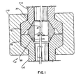
- Tubular joint 10 of the present invention is shown in FIGURE 1, and includes tubular members 12 and 14 having flanges 16 and 18 which are secured together by clamp 20 of a known design.
- the interior adjacent ends of tubular members 12 and 14 are tapered at 22 and 24 to provide sealing surfaces and seal ring 26 is positioned between members 12 and 14.
- the inner surface 28 of seal ring 26 is an axial surface and is parallel to and aligned with the inner surfaces of members 12 and 14.
- Seal ring 26 is generally triangular in section and its other two sides 30 and 32 are tapered and mate with surfaces 22 and 24 to ensure sealing engagement of seal ring 26 therewith as clamp 20 is tightened to bring flanges 16 and 18 and tubular members 12 and 14 together.
- Seal ring 26 as described above is substantially similar to seal ring 26a of the prior art as shown in FIGURE 4.
- the components of seal ring 26a of the prior art are given the same numbers in FIGURE 4 as the components of seal ring 26 of the present invention with all components of seal ring 26a having the postscript "a" following their number designations.
- seal ring 26 and seal ring 26a of the prior art The difference between seal ring 26 and seal ring 26a of the prior art is that means is provided to establish communication between a position midway on lower surface 30 to inner surface 28. Such communication means includes ports 34 which extend from groove 35 which is positioned midway of surface 30 through ring 26 to surface 28 as shown. With tubular joint 10 completed as shown a leak therein which develops between surface 22 and 30 is a controlled washout or erosion on surfaces 22 and 30 down to the level of groove 35. As shown in FIGURES 2 and 3, surface 22 includes eroded surface 36 and undamaged surface 38. Since surface 38 is undamaged, seal ring 26 can be removed and seal ring 40 which is a prior art seal ring similar to seal ring 26a in that it does not include ports 34 and groove 35 is installed in position between members 12 and 14. Seal ring 40 includes sealing surfaces 42 and 44. When installed, surface42 seals against surface 24and surface 44 seals against undamaged surface portion 38 of surface 22 as shown in FIGURE 3.
- the joint 50 shown in FIGURE 5 includes tubular members 52 and 54 having their adjoining ends prepared to have tapered sealing surfaces 56 and 58 respectively and seal ring 60 which is generally triangular in shape and includes outer tapered surfaces 62 and 64 which mate with sealing surfaces 56 and 58 as shown to provide the joint seal.
- Groove 66 is positioned midway in surface 62 and port 68 extends from groove 66 to inner surface 70 of seal ring 60.
- Groove 72 is positioned midway in surface 64 and port 74 extends from groove 72 to inner surface 70 of seal ring 60.
- seal ring 60 When joint 50 is subjected to erosion it is only necessary to remove seal ring 60 and replace it with a prior art seal ring which will seal against undamaged tapered sealing surface 58 and against undamaged portion 76 of sealing surface 56.
- the erosion of the sealing surface of the tubular members is controlled and the joint may be reassembled as a sealed joint without resurfacing the eroded sealing surface.
- seal ring 26 care should be taken in its installation so that groove 35 and ports 34 are on the lower outer surface. This allows the joint to be resealed as described above without reworking tapered surface 22. With seal ring 60 it may be installed in either position and no reworking is required to reseal the joint.
Claims (11)
Priority Applications (1)
| Application Number | Priority Date | Filing Date | Title |
|---|---|---|---|
| AT84302375T ATE23736T1 (de) | 1983-04-28 | 1984-04-06 | Rohrfoermige verbindung. |
Applications Claiming Priority (2)
| Application Number | Priority Date | Filing Date | Title |
|---|---|---|---|
| US06/489,495 US4474381A (en) | 1983-04-28 | 1983-04-28 | Metal pipe joint seal ring with port to control erosion |
| US489495 | 1983-04-28 |
Publications (2)
| Publication Number | Publication Date |
|---|---|
| EP0124304A1 EP0124304A1 (fr) | 1984-11-07 |
| EP0124304B1 true EP0124304B1 (fr) | 1986-11-20 |
Family
ID=23944109
Family Applications (1)
| Application Number | Title | Priority Date | Filing Date |
|---|---|---|---|
| EP84302375A Expired EP0124304B1 (fr) | 1983-04-28 | 1984-04-06 | Raccord tubulaire |
Country Status (9)
| Country | Link |
|---|---|
| US (1) | US4474381A (fr) |
| EP (1) | EP0124304B1 (fr) |
| JP (1) | JPS59208292A (fr) |
| AT (1) | ATE23736T1 (fr) |
| CA (1) | CA1227511A (fr) |
| DE (1) | DE3461393D1 (fr) |
| MX (1) | MX160554A (fr) |
| NO (1) | NO163917C (fr) |
| SG (1) | SG32687G (fr) |
Families Citing this family (26)
| Publication number | Priority date | Publication date | Assignee | Title |
|---|---|---|---|---|
| DE3877182T2 (de) * | 1988-03-01 | 1993-05-06 | Cooper Ind Inc | Rohrverbindung mit dichtung, verfahren zur dichtungsreparatur und einsatzreparaturteil. |
| JPH0236692U (fr) * | 1988-09-02 | 1990-03-09 | ||
| NO167474C (no) * | 1988-12-27 | 1991-11-06 | Friele Trading As | System til opprettelse av tetningsforbindelse mellom to aksialt sammenstoetende deler i en roerledning |
| US6070912A (en) * | 1989-08-01 | 2000-06-06 | Reflange, Inc. | Dual seal and connection |
| US5050843A (en) * | 1990-08-15 | 1991-09-24 | Manifold Systems, Inc. | Plug valve with metal-to-metal sealing |
| US5103915A (en) * | 1990-08-17 | 1992-04-14 | Abb Vetco Gray Inc. | Wellhead housing seal assembly for damaged sealing surfaces |
| US5839765A (en) * | 1996-11-01 | 1998-11-24 | Cooper Cameron Corporation | Metal seal ring for tubular joint |
| US6325390B1 (en) * | 1997-08-08 | 2001-12-04 | Itt Manufacturing Enterprises, Inc. | Vacuum flange O-ring center ring |
| US6409176B2 (en) | 1998-10-05 | 2002-06-25 | Cooper Cameron Corporation | Wellhead housing seal assembly with backup feature |
| NO308329B1 (no) * | 1999-01-28 | 2000-08-28 | Den Norske Metallpakningsfabri | Tetningsarrangement |
| US6357760B1 (en) * | 2000-05-19 | 2002-03-19 | Michael Doyle | Ring seal |
| US7107662B1 (en) * | 2000-12-21 | 2006-09-19 | Gene W. Arant, as Trustee | Method and a coupler for joining two steel pipes |
| US6450507B2 (en) | 2001-02-01 | 2002-09-17 | Abb Vetco Gray Inc. | Water ingress seal for tapered seals |
| US20060254041A1 (en) * | 2001-12-21 | 2006-11-16 | Levario Alfredo G | Flared liner method of securing thermoplastically lined metal pipe |
| JP2004286195A (ja) * | 2003-03-25 | 2004-10-14 | Nichias Corp | リング型金属ガスケット |
| GB2438631B (en) * | 2006-06-02 | 2008-02-13 | Alan Stewart Paton | Bimetal Bore Seal |
| US8561995B2 (en) * | 2009-06-30 | 2013-10-22 | Vetco Gray Inc. | Metal-to-metal annulus seal arrangement |
| WO2012151558A2 (fr) * | 2011-05-04 | 2012-11-08 | Gallagher Anthony David | Accouplement pour sections de tuyauterie en pvc |
| CN102853078A (zh) * | 2012-09-18 | 2013-01-02 | 中国船舶重工集团公司第七�三研究所 | 锅炉小口径联箱锥形内压密封机构 |
| CN102865367A (zh) * | 2012-09-19 | 2013-01-09 | 中国船舶重工集团公司第七�三研究所 | 锅炉小口径联箱锥形内压密封装置 |
| KR20150066541A (ko) * | 2012-10-04 | 2015-06-16 | 볼텍 리미티드 | 환상 씰 및 파이프의 밀봉 방법 |
| CN103498938B (zh) * | 2013-08-21 | 2016-01-20 | 中国海洋石油总公司 | 用于深水垂直连接器的密封件 |
| KR20170025336A (ko) * | 2015-08-28 | 2017-03-08 | 두산인프라코어 주식회사 | 이물질 유입방지 실 및 이를 포함하는 건설기계 |
| CN105179692B (zh) * | 2015-09-24 | 2018-03-09 | 北京精密机电控制设备研究所 | 一种紧凑式冗余密封结构 |
| US10161213B2 (en) * | 2016-07-26 | 2018-12-25 | Cameron International Corporation | Internal and external pressure seal assembly |
| US11859757B2 (en) * | 2020-12-04 | 2024-01-02 | Caterpillar Inc. | Fluid conduits with selectively coated surfaces |
Family Cites Families (12)
| Publication number | Priority date | Publication date | Assignee | Title |
|---|---|---|---|---|
| US1567813A (en) * | 1920-08-30 | 1925-12-29 | Olaf E Oleson | Pipe fitting |
| US2179355A (en) * | 1935-08-19 | 1939-11-07 | Super Diesel Tractor Corp | Coupling |
| DE801604C (de) * | 1948-10-02 | 1951-01-15 | Basf Ag | Selbstdichtender Konus |
| US2766999A (en) * | 1954-02-12 | 1956-10-16 | Gray Tool Co | Conduit connection with conically formed interengaging seats on seal and connection members |
| DE969600C (de) * | 1955-04-01 | 1958-07-03 | Mannesmann Ag | Rohrverbindung fuer Mehrlagenrohre |
| US2760673A (en) * | 1955-04-27 | 1956-08-28 | Frank A Rudman | Seal for vacuum vessels |
| DE1118550B (de) * | 1957-04-30 | 1961-11-30 | Heinz Bechler | Rohrverbindung fuer Hochdruck-, insbesondere Hoechstdruckleitungen |
| US3404902A (en) * | 1965-11-09 | 1968-10-08 | Gray Tool Co | Deflectable lip sealing connection having spoiler feature |
| USRE27389E (en) * | 1970-06-05 | 1972-06-13 | Pipe joint | |
| GB2025555A (en) * | 1978-07-03 | 1980-01-23 | Rocky Mountain Nuclear | Conduit connector |
| US4214763A (en) * | 1978-10-23 | 1980-07-29 | Latham Raymond E | Bore seal |
| DE3103551C2 (de) * | 1981-02-03 | 1986-09-11 | Kempchen & Co Gmbh, 4200 Oberhausen | Dichtungsanordnung für Flanschdichtungen |
-
1983
- 1983-04-28 US US06/489,495 patent/US4474381A/en not_active Expired - Lifetime
-
1984
- 1984-04-03 CA CA000451221A patent/CA1227511A/fr not_active Expired
- 1984-04-06 DE DE8484302375T patent/DE3461393D1/de not_active Expired
- 1984-04-06 EP EP84302375A patent/EP0124304B1/fr not_active Expired
- 1984-04-06 AT AT84302375T patent/ATE23736T1/de not_active IP Right Cessation
- 1984-04-13 MX MX201026A patent/MX160554A/es unknown
- 1984-04-27 NO NO841681A patent/NO163917C/no unknown
- 1984-04-27 JP JP59086006A patent/JPS59208292A/ja active Pending
-
1987
- 1987-04-07 SG SG326/87A patent/SG32687G/en unknown
Also Published As
| Publication number | Publication date |
|---|---|
| NO163917C (no) | 1990-08-08 |
| DE3461393D1 (en) | 1987-01-08 |
| MX160554A (es) | 1990-03-22 |
| JPS59208292A (ja) | 1984-11-26 |
| EP0124304A1 (fr) | 1984-11-07 |
| ATE23736T1 (de) | 1986-12-15 |
| US4474381A (en) | 1984-10-02 |
| CA1227511A (fr) | 1987-09-29 |
| NO163917B (no) | 1990-04-30 |
| NO841681L (no) | 1984-10-29 |
| SG32687G (en) | 1988-03-04 |
Similar Documents
| Publication | Publication Date | Title |
|---|---|---|
| EP0124304B1 (fr) | Raccord tubulaire | |
| US6305719B1 (en) | Pipe repair clamp | |
| US4426095A (en) | Flexible seal | |
| US5947533A (en) | Gasket assembly with elastomer expansion area | |
| EP0464050B1 (fr) | Joints etanches | |
| US4428603A (en) | Flange union with improved metal-to-metal seals | |
| EP0029338B1 (fr) | Manchon de serrage et procédé d'étanchéification | |
| US6652231B2 (en) | Cloth seal for an inner compressor discharge case and methods of locating the seal in situ | |
| US4403795A (en) | Flange union with improved recessed seats and sealing ring | |
| EP0764251A1 (fr) | Raccord à friction hermétique pour tuyau | |
| CA2253219A1 (fr) | Methode et appareil permettant de reduire au minimum les fuites dans des joints d'une turbine | |
| US4593914A (en) | Wellhead sealing system | |
| US4494762A (en) | Gasket and gasket manufacturing method | |
| US5029878A (en) | Elastomeric pump casing seal | |
| CN105972375A (zh) | 无人船载管线维修夹具 | |
| CN1099855A (zh) | 维修用管接头 | |
| EP0091254A3 (fr) | Raccord de tuyaux et garniture | |
| US5251942A (en) | Self-sealing pipe thread | |
| US5890535A (en) | Diverter flow line seal | |
| EP0330769B1 (fr) | Joint tubulaire avec garniture d'étanchéité, procédé pour la réparation de la garniture et pièce de réparation | |
| EP0086291B1 (fr) | Joint d'étanchéité pour un passage d'huile pour machines | |
| US2632942A (en) | Method of joining together glass pipe sections | |
| EP0334389A2 (fr) | Joints d'étanchéité pour têtes de puits | |
| JPS61160690A (ja) | 高圧管継手 | |
| US4572583A (en) | Cutting head for drift advancing machines and process for producing same |
Legal Events
| Date | Code | Title | Description |
|---|---|---|---|
| PUAI | Public reference made under article 153(3) epc to a published international application that has entered the european phase |
Free format text: ORIGINAL CODE: 0009012 |
|
| AK | Designated contracting states |
Designated state(s): AT BE CH DE FR GB IT LI LU NL SE |
|
| 17P | Request for examination filed |
Effective date: 19850222 |
|
| 17Q | First examination report despatched |
Effective date: 19860203 |
|
| GRAA | (expected) grant |
Free format text: ORIGINAL CODE: 0009210 |
|
| AK | Designated contracting states |
Kind code of ref document: B1 Designated state(s): AT BE CH DE FR GB IT LI LU NL SE |
|
| PG25 | Lapsed in a contracting state [announced via postgrant information from national office to epo] |
Ref country code: LI Effective date: 19861120 Ref country code: CH Effective date: 19861120 Ref country code: BE Effective date: 19861120 |
|
| REF | Corresponds to: |
Ref document number: 23736 Country of ref document: AT Date of ref document: 19861215 Kind code of ref document: T |
|
| ITF | It: translation for a ep patent filed |
Owner name: JACOBACCI & PERANI S.P.A. |
|
| PG25 | Lapsed in a contracting state [announced via postgrant information from national office to epo] |
Ref country code: SE Effective date: 19861130 |
|
| ET | Fr: translation filed | ||
| REF | Corresponds to: |
Ref document number: 3461393 Country of ref document: DE Date of ref document: 19870108 |
|
| REG | Reference to a national code |
Ref country code: CH Ref legal event code: PL |
|
| PG25 | Lapsed in a contracting state [announced via postgrant information from national office to epo] |
Ref country code: LU Free format text: LAPSE BECAUSE OF NON-PAYMENT OF DUE FEES Effective date: 19870430 |
|
| PLBE | No opposition filed within time limit |
Free format text: ORIGINAL CODE: 0009261 |
|
| STAA | Information on the status of an ep patent application or granted ep patent |
Free format text: STATUS: NO OPPOSITION FILED WITHIN TIME LIMIT |
|
| 26N | No opposition filed | ||
| REG | Reference to a national code |
Ref country code: GB Ref legal event code: 732 |
|
| PGFP | Annual fee paid to national office [announced via postgrant information from national office to epo] |
Ref country code: AT Payment date: 19920319 Year of fee payment: 9 |
|
| PGFP | Annual fee paid to national office [announced via postgrant information from national office to epo] |
Ref country code: GB Payment date: 19920323 Year of fee payment: 9 |
|
| PGFP | Annual fee paid to national office [announced via postgrant information from national office to epo] |
Ref country code: FR Payment date: 19920410 Year of fee payment: 9 |
|
| PGFP | Annual fee paid to national office [announced via postgrant information from national office to epo] |
Ref country code: DE Payment date: 19920427 Year of fee payment: 9 |
|
| ITTA | It: last paid annual fee | ||
| PGFP | Annual fee paid to national office [announced via postgrant information from national office to epo] |
Ref country code: NL Payment date: 19920430 Year of fee payment: 9 |
|
| PG25 | Lapsed in a contracting state [announced via postgrant information from national office to epo] |
Ref country code: GB Effective date: 19930406 Ref country code: AT Effective date: 19930406 |
|
| PG25 | Lapsed in a contracting state [announced via postgrant information from national office to epo] |
Ref country code: NL Effective date: 19931101 |
|
| GBPC | Gb: european patent ceased through non-payment of renewal fee |
Effective date: 19930406 |
|
| NLV4 | Nl: lapsed or anulled due to non-payment of the annual fee | ||
| PG25 | Lapsed in a contracting state [announced via postgrant information from national office to epo] |
Ref country code: FR Effective date: 19931229 |
|
| PG25 | Lapsed in a contracting state [announced via postgrant information from national office to epo] |
Ref country code: DE Effective date: 19940101 |
|
| REG | Reference to a national code |
Ref country code: FR Ref legal event code: ST |