EP0124098A2 - Dokumentenabtaster mit Positionierungsgerät - Google Patents
Dokumentenabtaster mit Positionierungsgerät Download PDFInfo
- Publication number
- EP0124098A2 EP0124098A2 EP84104727A EP84104727A EP0124098A2 EP 0124098 A2 EP0124098 A2 EP 0124098A2 EP 84104727 A EP84104727 A EP 84104727A EP 84104727 A EP84104727 A EP 84104727A EP 0124098 A2 EP0124098 A2 EP 0124098A2
- Authority
- EP
- European Patent Office
- Prior art keywords
- document
- scanner
- planar element
- scanning
- accordance
- Prior art date
- Legal status (The legal status is an assumption and is not a legal conclusion. Google has not performed a legal analysis and makes no representation as to the accuracy of the status listed.)
- Granted
Links
- 238000005286 illumination Methods 0.000 claims description 7
- 239000000463 material Substances 0.000 claims 1
- 239000002184 metal Substances 0.000 claims 1
- 230000005540 biological transmission Effects 0.000 abstract description 4
- 238000000034 method Methods 0.000 description 7
- 239000011521 glass Substances 0.000 description 6
- 238000003491 array Methods 0.000 description 4
- 238000010586 diagram Methods 0.000 description 2
- 238000001816 cooling Methods 0.000 description 1
- 238000011161 development Methods 0.000 description 1
- 230000018109 developmental process Effects 0.000 description 1
- 230000000694 effects Effects 0.000 description 1
- 230000006870 function Effects 0.000 description 1
- 239000011159 matrix material Substances 0.000 description 1
- 239000005304 optical glass Substances 0.000 description 1
- 230000002093 peripheral effect Effects 0.000 description 1
- 229910001220 stainless steel Inorganic materials 0.000 description 1
- 239000010935 stainless steel Substances 0.000 description 1
Images


Classifications
-
- H—ELECTRICITY
- H04—ELECTRIC COMMUNICATION TECHNIQUE
- H04N—PICTORIAL COMMUNICATION, e.g. TELEVISION
- H04N1/00—Scanning, transmission or reproduction of documents or the like, e.g. facsimile transmission; Details thereof
- H04N1/04—Scanning arrangements, i.e. arrangements for the displacement of active reading or reproducing elements relative to the original or reproducing medium, or vice versa
- H04N1/10—Scanning arrangements, i.e. arrangements for the displacement of active reading or reproducing elements relative to the original or reproducing medium, or vice versa using flat picture-bearing surfaces
- H04N1/1013—Scanning arrangements, i.e. arrangements for the displacement of active reading or reproducing elements relative to the original or reproducing medium, or vice versa using flat picture-bearing surfaces with sub-scanning by translatory movement of at least a part of the main-scanning components
- H04N1/1021—Scanning arrangements, i.e. arrangements for the displacement of active reading or reproducing elements relative to the original or reproducing medium, or vice versa using flat picture-bearing surfaces with sub-scanning by translatory movement of at least a part of the main-scanning components using a lead screw or worm
-
- H—ELECTRICITY
- H04—ELECTRIC COMMUNICATION TECHNIQUE
- H04N—PICTORIAL COMMUNICATION, e.g. TELEVISION
- H04N1/00—Scanning, transmission or reproduction of documents or the like, e.g. facsimile transmission; Details thereof
- H04N1/04—Scanning arrangements, i.e. arrangements for the displacement of active reading or reproducing elements relative to the original or reproducing medium, or vice versa
- H04N1/10—Scanning arrangements, i.e. arrangements for the displacement of active reading or reproducing elements relative to the original or reproducing medium, or vice versa using flat picture-bearing surfaces
- H04N1/1013—Scanning arrangements, i.e. arrangements for the displacement of active reading or reproducing elements relative to the original or reproducing medium, or vice versa using flat picture-bearing surfaces with sub-scanning by translatory movement of at least a part of the main-scanning components
- H04N1/1039—Movement of the main scanning components
- H04N1/1043—Movement of the main scanning components of a sensor array
-
- H—ELECTRICITY
- H04—ELECTRIC COMMUNICATION TECHNIQUE
- H04N—PICTORIAL COMMUNICATION, e.g. TELEVISION
- H04N1/00—Scanning, transmission or reproduction of documents or the like, e.g. facsimile transmission; Details thereof
- H04N1/04—Scanning arrangements, i.e. arrangements for the displacement of active reading or reproducing elements relative to the original or reproducing medium, or vice versa
- H04N1/19—Scanning arrangements, i.e. arrangements for the displacement of active reading or reproducing elements relative to the original or reproducing medium, or vice versa using multi-element arrays
- H04N1/191—Scanning arrangements, i.e. arrangements for the displacement of active reading or reproducing elements relative to the original or reproducing medium, or vice versa using multi-element arrays the array comprising a one-dimensional array, or a combination of one-dimensional arrays, or a substantially one-dimensional array, e.g. an array of staggered elements
- H04N1/192—Simultaneously or substantially simultaneously scanning picture elements on one main scanning line
- H04N1/193—Simultaneously or substantially simultaneously scanning picture elements on one main scanning line using electrically scanned linear arrays, e.g. linear CCD arrays
-
- H—ELECTRICITY
- H04—ELECTRIC COMMUNICATION TECHNIQUE
- H04N—PICTORIAL COMMUNICATION, e.g. TELEVISION
- H04N2201/00—Indexing scheme relating to scanning, transmission or reproduction of documents or the like, and to details thereof
- H04N2201/04—Scanning arrangements
- H04N2201/0402—Arrangements not specific to a particular one of the scanning methods covered by groups H04N1/04 - H04N1/207
- H04N2201/0422—Media holders, covers, supports, backgrounds; Arrangements to facilitate placing of the medium
-
- H—ELECTRICITY
- H04—ELECTRIC COMMUNICATION TECHNIQUE
- H04N—PICTORIAL COMMUNICATION, e.g. TELEVISION
- H04N2201/00—Indexing scheme relating to scanning, transmission or reproduction of documents or the like, and to details thereof
- H04N2201/04—Scanning arrangements
- H04N2201/0402—Arrangements not specific to a particular one of the scanning methods covered by groups H04N1/04 - H04N1/207
- H04N2201/0436—Scanning a picture-bearing surface lying face up on a support
Definitions
- This invention relates generally to a document scanner for facsimile systems and office information systems and more specifically to a raster image scanner, used to scan and digitize documents employing CCD arrays.
- Office information systems include computers and associated peripherals such as monitors, e.g. a cathode ray tube (CRT), mass storage devices and printers to keep track of, to manipulate and to distribute information necessary to the activities of an office.
- monitors e.g. a cathode ray tube (CRT)
- mass storage devices and printers to keep track of, to manipulate and to distribute information necessary to the activities of an office.
- printers deal only with-structured, digital data representing the information. Text and graphic information displayed on a monitor or printed out by a printer are created solely from structured data.
- document scanning devices are now being added to such office information systems such as described in European Patent Application No. 83111155, entitled Communication Terminal for an Office Information System and having a common inventor with this present patent application. This patent application is incorporated herein by reference.
- such office information systems now include a scanner with a graphic data generator in the form of a camera for scanning a document to create a signal representing the information on the document, and the signal may be used to display the document on the video display associated with the scanning camera, or the signal may be stored for future use, or the signal may be transmitted to a remote location for displaying the document via a printer or a video terminal thereat.
- CCD charge coupled device
- CCD arrays There is one problem in prior art document scanning system utilizing CCD arrays. Using CCD arrays it typically takes several seconds to completely scan a document. Then the digitized information resulting from the scanning process is used to redisplay the document on the video display or a printer to verify that the desired portion of the document has been scanned. Normally this is not the case and the document must be repositioned and the scanning process repeated with the results again being checked. This process is often repeated several times in order to properly position a document under the scanning device to scan the desired portion of the document. This can take an inordinate amount of time which is unacceptable to a busy executive.
- a document scanner comprising a positioning device which functions with a scanning camera to assure that a document may be quickly and easily positioned and the desired portion of the document be scanned the first time.
- the positioning device is used to project a pattern or frame on an easel in front of the scanning camera and on which a document to be scanned is placed.
- the projected pattern indicates the boundaries of the area or site area that will subsequently be scanned by the camera.
- the operator positions a document with the projected pattern thereon to locate the portion of the document to be scanned within the projected boundary areas. Thereafter, the operator operates a control which extinguishes the projected pattern and causes the scanning camera to scan the document.
- the signals from the scanning process are in analog form and are applied to an analog-to-digital converter to digitize the information on the document.
- the invention may be utilized with a scanning camera operating solely in a document facsimile transmission system or in conjunction with other office information equipment systems to implement a communication terminal.
- Apparatus 10 in Fig.l is an office information system operable as a communication terminal and includes a video terminal or monitor 11 with a keyboard 12, a printer 13, a console 14, and a CCD scanner/digitizer 15 which utilizes the present invention. All this equipment is supported on table top 16. The cabling interconnecting these equipment is not shown but should be understood to be present.
- Video monitor 11, keyboard 12, printer 13 and console 14 are the standard parts of the computer, and scanner digitizer 15 is added to make the computer into a communication terminal.
- the interface circuitry, device controllers, memory and communication controller and other parts that make up the terminal are housed in console 14 along with the circuitry for the computer.
- Two such office information systems 10 and 10A functioning as communication terminals may be interconnected via a telecommunications link (not shown) to permit communications between the systems including the transmission of scanned and digitized documents.
- Documents such as document 17 on easel 18 of scanner digitizer 15 may have any combination of alphanumeric and graphic information to be scanned and digitized.
- scanner digitizer 15 also serves as a personal facsimile machine with a document 17 being scanned and digitized at one office information and system then transmitted via a telecommunications link to another office information system 10A to be reproduced at the printer 13 thereat.
- printer 13 most advantageously should be a dot matrix printer.
- FIG.2 as shown in the block diagram of two office information systems 10 and 10A interconnected by a telecommunications link 27.
- Each office information system 10 and 10A respectively, has a console 14 and 14A, video display 11 and 11A, a keyboard 12 and 12A, a printer 13 and 13A, and a scanner 15 and 15A.
- a bus which is bus 25 for system 10 and bus 26 for system 10A.
- controller 19 Within console 14 of office information system 10 is a controller 19 which is advan - tageously a microprocessor system, a buffer memory 20 and a communications interface 21 via which system 10 is connected to telecommunications link 27.
- Office information system 10A has similar elements 22, 23 and 24 within console 14A.
- a document that may have alphanumeric and/or graphic information thereon is digitized by scanner 15 and the resultant digital information is stored in buffer memory 20 of console 14.
- This digitized information then may be read out of buffer memory 20 by controller 19 and used to display the document on the monitor display 11 or to print the document out on printer 13.
- the digitized information representing the document may be also passed via communications interface 21 under the control of controller 19 and via telecommunications link 27 to office information system 10A to be stored in buffer memory 23 thereat.
- Controller 22 may then read the digitized information out of buffer memory 23 to reproduce the document on video display 11A or to reproduce a hard copy via printer 13A.
- a document digitized at office information system 10A may be transmitted to system 10 to be reproduced thereat. It is in this setting that the novel scanner 15 and 15A with document positioning devices are utilized with each systems 10 and 10A respectively, to facilitate the scanning and transmission of documents.
- each physical location will have a scanner 15 to scan documents, a printer 13 to reproduce documents and a communications interface 21 to interface printer 13 and scanner 15 to a communications link to transmit signals to and receive signals from a remote facsimile system that may or may not be made up of the same combination of equipment.
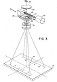
- Fig.3 is shown a few of the elements within scanners 15 and 15A and including those elements making up its document positioning device.
- a document (not shown) is placed upon easel 18 for scanning and digitizing.
- the document is illuminated by a light source (not shown) made up of two 150 watt projection lamps and the light reflected from the illuminated document is received by lens 31 which focuses it upon a plane across which CCD array 28 will be moved to scan the document in a manner well known in the art.
- buring the scanning process motor 30 is energized to turn lead screw 29 along which a carrier upon which CCD array--P8 is mounted is moved.
- the CCD array 28 is moved in the direction of lead screw 29.
- individual elements of CCD array 28 are sampled in a time division multiplexing operation and the outputs are digitized by an analog-to-digital converter (not shown) in a manner well known in the art to digitize the document.
- the housing in which all these elements are mounted may be moved vertically to be closer to or further away from a document on easel 18.
- the image of the document is smaller and the area to be scanned will be smaller.
- lens 31 must be adjusted to focus the document on easel 18 to be scanned.
- An image 37 indicating the image area that will be scanned is projected onto easel 18 in accordance with the teaching of the invention and facilitates this focusing. Since a reticle 34 on which is located the original to image 37 lies in the image plane across which the CCD scanner 28 passes, when image 37 is sharp and clear lens 31 is properly adjusted. In this manner the operator of the scanner may change the size of the area to be scanned and thereby achieve a closeup type operation and may quickly and easily achieve focus using lens 31.
- the housing may be moved vertically such that the distance between the reticle (image plane) and the easel is between 23 cm and 44 cm.
- the distance between the reticle (image plane) and the easel is between 23 cm and 44 cm.
- a 10,8 cm by 14 cm area is scanned.
- an 28 cm by 35,6 cm area is scanned. Vertical settings in between the limits will scan areas between these areas.
- the document positioning apparatus of the scanner comprises a lamp 32, heat absorbing glass 33, a light distributing lens made up of two fresnel lenses 35 and 36, and sandwiched thereto is a reticle 34 upon which is a small representation of the image 37 shown on easel 18.
- Elements 34, 35 and 36 are attached to the CCD array 28 carrier and lie in the aforementioned image plane.
- fresnel lenses 35 and 36 can be replaced by a 70 millimeter condenser lens made up of a pair of plane convex lenses as is known in the art.
- the operator of the scanner places a document (not shown) upon easel 18 and then operates a control on the scanner to energize lamp 32.
- Lamp 32 will remain energized for a fixed period of time such as ten seconds at the end of which it will automatically be extinguished. However, if the operator of the scanner operates another control to place the scanner in the scan mode lamp 32 is also extinguished, even though the arbitrary period such as ten seconds has not expired, and the document upon easel 18 is then scanned in the manner well known in the art.
- Absorbing glass 33 is a transparent heat absorbing glass which protects reticle 34 and lenses 35 and 36 from the heat generated by 150 watt projection lamp 32 in order to project image 37 onto easel 18 under normal room lighting conditions. Glass 33 is approximately equivalent to KG1 glass and may be obtained from many sources including Schott Optical Glass Inc., 400 York Avenue, Duryea, Pennsylvania.
- Lenses 35 and 36 cooperate to evenly distribute light generated by illumination means 32 upon reticle 34 to insure an evenly illuminated image 37 on easel 18 and to provide maximum throughput of light to enhance the projected image.
- Lamp 32 being energized causes light to pass through glass 33, reticle 34 and lenses 35 and 36 and then through lens 31 to project the image of reticle 34 onto easel 18 as shown by image 37 thereon.
- Image 37 defines the area on easel 18 that will be scanned by CCD scanner 28 when the scanning process is commenced.
- Reticle 34 is a thin sheet of stainless steel having the image etched therethrough. The operator of the scanner has two adjustments they can make.
Landscapes
- Engineering & Computer Science (AREA)
- Multimedia (AREA)
- Signal Processing (AREA)
- Facsimile Scanning Arrangements (AREA)
- Facsimiles In General (AREA)
- Image Input (AREA)
Applications Claiming Priority (2)
| Application Number | Priority Date | Filing Date | Title |
|---|---|---|---|
| US06/489,642 US4514063A (en) | 1983-04-28 | 1983-04-28 | Scanner document positioning device |
| US489642 | 1983-04-28 |
Publications (3)
| Publication Number | Publication Date |
|---|---|
| EP0124098A2 true EP0124098A2 (de) | 1984-11-07 |
| EP0124098A3 EP0124098A3 (en) | 1986-02-12 |
| EP0124098B1 EP0124098B1 (de) | 1988-03-30 |
Family
ID=23944676
Family Applications (1)
| Application Number | Title | Priority Date | Filing Date |
|---|---|---|---|
| EP84104727A Expired EP0124098B1 (de) | 1983-04-28 | 1984-04-26 | Dokumentenabtaster mit Positionierungsgerät |
Country Status (6)
| Country | Link |
|---|---|
| US (1) | US4514063A (de) |
| EP (1) | EP0124098B1 (de) |
| JP (1) | JPS59204370A (de) |
| AU (1) | AU561837B2 (de) |
| CA (1) | CA1208363A (de) |
| DE (1) | DE3470268D1 (de) |
Cited By (9)
| Publication number | Priority date | Publication date | Assignee | Title |
|---|---|---|---|---|
| EP0200814A1 (de) * | 1985-04-05 | 1986-11-12 | Opti-Copy, Inc. | Verfahren und Vorrichtung zum Ausrichten von Teilfarbfilmen |
| DE3606765A1 (de) * | 1986-03-01 | 1987-09-03 | Strahlen Umweltforsch Gmbh | Kamera zur optoelektronischen abtastung einer beliebigen szene |
| EP0282652A1 (de) * | 1985-09-20 | 1988-09-21 | Gunvor Westin | Verfahren zur Dokumentation von zwei- oder dreidimensionale Objekte |
| EP0320567A1 (de) * | 1987-12-11 | 1989-06-21 | Buderus Sell GmbH | Textilmusterabtastverfahren und Vorrichtung zur Durchführung des Verfahrens |
| DE4113594A1 (de) * | 1991-04-25 | 1992-11-12 | Josef Kirmeier | Scanner-kamera mit digitaler signalausgabe und fokussierungssystem, vorgesehen als teil einer druckschriften-kopiervorrichtung |
| WO1993025040A1 (de) * | 1992-06-04 | 1993-12-09 | Josef Kirmeier | Kopiervorrichtung |
| EP0751664A2 (de) * | 1995-06-29 | 1997-01-02 | Bayer Corporation | Vorrichtung zur Ausrichtung von Abtastmaterial in einem Flachbettabtaster |
| EP1152596A2 (de) * | 2000-04-27 | 2001-11-07 | Josef Lindthaler | Vorrichtung und Verfahren zur Erstellung eines Bildabzuges von einer Bildvorlage |
| EP2790404A3 (de) * | 2013-04-12 | 2014-11-19 | Funai Electric Co., Ltd. | Elektronisches Gerät |
Families Citing this family (14)
| Publication number | Priority date | Publication date | Assignee | Title |
|---|---|---|---|---|
| JPS61122623A (ja) * | 1984-11-19 | 1986-06-10 | Canon Inc | 投影装置 |
| JPH0827437B2 (ja) * | 1986-10-24 | 1996-03-21 | キヤノン株式会社 | 画像入力装置 |
| US4953971A (en) * | 1988-10-17 | 1990-09-04 | Highfill Robert R | Interactive image projection apparatus |
| US5214460A (en) * | 1991-11-04 | 1993-05-25 | Chuan Raymond L | Projector slide orientation rectification system |
| AU676667B2 (en) * | 1992-10-22 | 1997-03-20 | Kabushiki Kaisha Ace Denken | Screen display type slot machine |
| US5588216A (en) * | 1995-05-19 | 1996-12-31 | Harley-Davidson Motor Company | Gas tank graphic positioning fixture |
| US5663806A (en) * | 1995-10-03 | 1997-09-02 | International Business Machines Corp. | Non-destructive target marking for image stitching |
| EP1128655B1 (de) * | 2000-02-21 | 2006-12-06 | Hewlett-Packard Company, A Delaware Corporation | Hilfe zum Positionieren für Dokumenten-Scanner |
| US7903878B2 (en) * | 2006-03-30 | 2011-03-08 | Loquitur, Inc. | Capturing and presenting text during optical character recognition |
| US8208729B2 (en) * | 2006-03-30 | 2012-06-26 | Loquitur, Inc. | Capturing and presenting text using video image capture for optical character recognition |
| US20070280534A1 (en) * | 2006-06-05 | 2007-12-06 | Benjamin Perkins Foss | Method for capturing and presenting test using video image capture for optical character recognition |
| US20100135707A1 (en) * | 2006-09-01 | 2010-06-03 | Xerox Corporation | Scanner page alignment tools |
| US8594387B2 (en) * | 2007-04-23 | 2013-11-26 | Intel-Ge Care Innovations Llc | Text capture and presentation device |
| US9712704B2 (en) * | 2015-08-21 | 2017-07-18 | Xerox Corporation | Scanner providing centered alignment marks |
Citations (1)
| Publication number | Priority date | Publication date | Assignee | Title |
|---|---|---|---|---|
| WO1981000944A1 (en) * | 1979-09-24 | 1981-04-02 | Datacopy Corp | Electronic camera employing a solid-state image sensor |
Family Cites Families (5)
| Publication number | Priority date | Publication date | Assignee | Title |
|---|---|---|---|---|
| US1750197A (en) * | 1926-12-08 | 1930-03-11 | Eastman Kodak Co | Heat-elimination screen for projector systems |
| US1916567A (en) * | 1929-04-01 | 1933-07-04 | Edwin J Grant | Apparatus for producing light boundaries |
| US3632197A (en) * | 1969-08-11 | 1972-01-04 | North American Rockwell | Viewing method and means |
| DD110366A1 (de) * | 1974-03-05 | 1974-12-12 | ||
| JPS586667A (ja) * | 1981-07-03 | 1983-01-14 | Fuji Photo Film Co Ltd | 平面走査方法及び装置 |
-
1983
- 1983-04-28 US US06/489,642 patent/US4514063A/en not_active Expired - Lifetime
- 1983-08-04 AU AU17581/83A patent/AU561837B2/en not_active Ceased
- 1983-09-19 JP JP58172868A patent/JPS59204370A/ja active Pending
- 1983-11-02 CA CA000440240A patent/CA1208363A/en not_active Expired
-
1984
- 1984-04-26 DE DE8484104727T patent/DE3470268D1/de not_active Expired
- 1984-04-26 EP EP84104727A patent/EP0124098B1/de not_active Expired
Patent Citations (1)
| Publication number | Priority date | Publication date | Assignee | Title |
|---|---|---|---|---|
| WO1981000944A1 (en) * | 1979-09-24 | 1981-04-02 | Datacopy Corp | Electronic camera employing a solid-state image sensor |
Cited By (15)
| Publication number | Priority date | Publication date | Assignee | Title |
|---|---|---|---|---|
| EP0200814A1 (de) * | 1985-04-05 | 1986-11-12 | Opti-Copy, Inc. | Verfahren und Vorrichtung zum Ausrichten von Teilfarbfilmen |
| EP0282652A1 (de) * | 1985-09-20 | 1988-09-21 | Gunvor Westin | Verfahren zur Dokumentation von zwei- oder dreidimensionale Objekte |
| DE3606765A1 (de) * | 1986-03-01 | 1987-09-03 | Strahlen Umweltforsch Gmbh | Kamera zur optoelektronischen abtastung einer beliebigen szene |
| US4755880A (en) * | 1986-03-01 | 1988-07-05 | Gesellschaft Fur Strahlen- Und Umweltforschung Mbh | Camera for opto-electronically scanning any desired scene |
| EP0320567A1 (de) * | 1987-12-11 | 1989-06-21 | Buderus Sell GmbH | Textilmusterabtastverfahren und Vorrichtung zur Durchführung des Verfahrens |
| DE4113594A1 (de) * | 1991-04-25 | 1992-11-12 | Josef Kirmeier | Scanner-kamera mit digitaler signalausgabe und fokussierungssystem, vorgesehen als teil einer druckschriften-kopiervorrichtung |
| WO1993025040A1 (de) * | 1992-06-04 | 1993-12-09 | Josef Kirmeier | Kopiervorrichtung |
| US5680228A (en) * | 1992-06-04 | 1997-10-21 | Kirmeier; Josef | Copying device which effects simultaneous scanning and printing |
| EP0751664A2 (de) * | 1995-06-29 | 1997-01-02 | Bayer Corporation | Vorrichtung zur Ausrichtung von Abtastmaterial in einem Flachbettabtaster |
| EP0751664A3 (de) * | 1995-06-29 | 1997-11-19 | Bayer Corporation | Vorrichtung zur Ausrichtung von Abtastmaterial in einem Flachbettabtaster |
| EP1152596A2 (de) * | 2000-04-27 | 2001-11-07 | Josef Lindthaler | Vorrichtung und Verfahren zur Erstellung eines Bildabzuges von einer Bildvorlage |
| EP1152596A3 (de) * | 2000-04-27 | 2004-03-10 | Josef Lindthaler | Vorrichtung und Verfahren zur Erstellung eines Bildabzuges von einer Bildvorlage |
| EP2790404A3 (de) * | 2013-04-12 | 2014-11-19 | Funai Electric Co., Ltd. | Elektronisches Gerät |
| US9372074B2 (en) | 2013-04-12 | 2016-06-21 | Funai Electric Co., Ltd. | Electronic device |
| US9581435B2 (en) | 2013-04-12 | 2017-02-28 | Funai Electric Co., Ltd. | Electronic device |
Also Published As
| Publication number | Publication date |
|---|---|
| AU561837B2 (en) | 1987-05-21 |
| JPS59204370A (ja) | 1984-11-19 |
| EP0124098B1 (de) | 1988-03-30 |
| EP0124098A3 (en) | 1986-02-12 |
| CA1208363A (en) | 1986-07-22 |
| DE3470268D1 (en) | 1988-05-05 |
| AU1758183A (en) | 1984-11-01 |
| US4514063A (en) | 1985-04-30 |
Similar Documents
| Publication | Publication Date | Title |
|---|---|---|
| EP0124098B1 (de) | Dokumentenabtaster mit Positionierungsgerät | |
| US5414535A (en) | Apparatus for reading image from original image on translucent film with automatic adjustment of the quantity of light from a light source | |
| US6466302B1 (en) | Scanning system with document previewing | |
| US5940049A (en) | Remote interactive projector with image enhancement | |
| EP0627705A2 (de) | Optischer Kodierungsleser | |
| WO1997016015A9 (en) | Remote interactive projector with image enhancement | |
| EP0901271A3 (de) | Zweilinsenkonvergenzvorrichtung in einem Flachbettabtaster mit zwei Abtastebenen | |
| US5067020A (en) | Dual sensor film scanner having coupled optics and a video viewfinder | |
| EP0901272A3 (de) | Einzellampen-Belichtungssystem für Doppelebenen-Flachbettabtaster | |
| EP0029327B1 (de) | Apparat und Verfahren zur Reproduktion von Bild- und Wortdaten | |
| US20070053018A1 (en) | Method for scanning selected target image area of document | |
| US4812915A (en) | Image reading apparatus which eliminates moire patterns by magnifying an image optically and reducing it electrically | |
| US6762862B2 (en) | High resolution scanner | |
| US5078487A (en) | Projecting apparatus | |
| JP3056329B2 (ja) | 読取原稿有無判別方法および装置 | |
| EP0197734A2 (de) | Mikroformlesevorrichtung | |
| JPS63279235A (ja) | 情報観察読取装置 | |
| JPH10155061A (ja) | 画像読取り装置 | |
| JPS61154261A (ja) | マイクロフイルム画像読取装置 | |
| JP2911134B2 (ja) | 原稿読取装置 | |
| JPH08241363A (ja) | コード読み取り装置及び記録媒体 | |
| JP2705144B2 (ja) | 座標入力手段を有した画像読取装置 | |
| CA1263925A (en) | Method and apparatus for mounting a ccd array used in a digital imaging system | |
| JPH1117878A (ja) | 原稿載置台及びそれを用いた画像読み取り装置 | |
| JPH07336568A (ja) | 画像入力装置 |
Legal Events
| Date | Code | Title | Description |
|---|---|---|---|
| PUAI | Public reference made under article 153(3) epc to a published international application that has entered the european phase |
Free format text: ORIGINAL CODE: 0009012 |
|
| AK | Designated contracting states |
Designated state(s): BE DE FR GB IT NL |
|
| PUAL | Search report despatched |
Free format text: ORIGINAL CODE: 0009013 |
|
| AK | Designated contracting states |
Designated state(s): BE DE FR GB IT NL |
|
| 17P | Request for examination filed |
Effective date: 19860327 |
|
| 17Q | First examination report despatched |
Effective date: 19870922 |
|
| GRAA | (expected) grant |
Free format text: ORIGINAL CODE: 0009210 |
|
| ITF | It: translation for a ep patent filed | ||
| AK | Designated contracting states |
Kind code of ref document: B1 Designated state(s): BE DE FR GB IT NL |
|
| REF | Corresponds to: |
Ref document number: 3470268 Country of ref document: DE Date of ref document: 19880505 |
|
| ET | Fr: translation filed | ||
| PLBE | No opposition filed within time limit |
Free format text: ORIGINAL CODE: 0009261 |
|
| STAA | Information on the status of an ep patent application or granted ep patent |
Free format text: STATUS: NO OPPOSITION FILED WITHIN TIME LIMIT |
|
| 26N | No opposition filed | ||
| REG | Reference to a national code |
Ref country code: FR Ref legal event code: TP Ref country code: FR Ref legal event code: GC Ref country code: FR Ref legal event code: AM |
|
| ITTA | It: last paid annual fee | ||
| PGFP | Annual fee paid to national office [announced via postgrant information from national office to epo] |
Ref country code: BE Payment date: 19920312 Year of fee payment: 9 |
|
| PGFP | Annual fee paid to national office [announced via postgrant information from national office to epo] |
Ref country code: NL Payment date: 19920430 Year of fee payment: 9 |
|
| PG25 | Lapsed in a contracting state [announced via postgrant information from national office to epo] |
Ref country code: BE Effective date: 19930430 |
|
| BERE | Be: lapsed |
Owner name: WANG LABORATORIES INC. Effective date: 19930430 |
|
| PG25 | Lapsed in a contracting state [announced via postgrant information from national office to epo] |
Ref country code: NL Effective date: 19931101 |
|
| NLV4 | Nl: lapsed or anulled due to non-payment of the annual fee | ||
| REG | Reference to a national code |
Ref country code: GB Ref legal event code: 732E |
|
| REG | Reference to a national code |
Ref country code: FR Ref legal event code: TP |
|
| PGFP | Annual fee paid to national office [announced via postgrant information from national office to epo] |
Ref country code: DE Payment date: 20000427 Year of fee payment: 17 |
|
| REG | Reference to a national code |
Ref country code: GB Ref legal event code: 732E |
|
| PGFP | Annual fee paid to national office [announced via postgrant information from national office to epo] |
Ref country code: FR Payment date: 20010409 Year of fee payment: 18 |
|
| PGFP | Annual fee paid to national office [announced via postgrant information from national office to epo] |
Ref country code: GB Payment date: 20010425 Year of fee payment: 18 |
|
| REG | Reference to a national code |
Ref country code: GB Ref legal event code: IF02 |
|
| PG25 | Lapsed in a contracting state [announced via postgrant information from national office to epo] |
Ref country code: DE Free format text: LAPSE BECAUSE OF NON-PAYMENT OF DUE FEES Effective date: 20020201 |
|
| REG | Reference to a national code |
Ref country code: FR Ref legal event code: TP |
|
| REG | Reference to a national code |
Ref country code: FR Ref legal event code: TP |
|
| PG25 | Lapsed in a contracting state [announced via postgrant information from national office to epo] |
Ref country code: GB Free format text: LAPSE BECAUSE OF NON-PAYMENT OF DUE FEES Effective date: 20020426 |
|
| GBPC | Gb: european patent ceased through non-payment of renewal fee |
Effective date: 20020426 |
|
| PG25 | Lapsed in a contracting state [announced via postgrant information from national office to epo] |
Ref country code: FR Free format text: LAPSE BECAUSE OF NON-PAYMENT OF DUE FEES Effective date: 20021231 |
|
| REG | Reference to a national code |
Ref country code: FR Ref legal event code: ST |