EP0122578B1 - Méthode de surveilalnce de fatigue d'éléments par exemple dans une centrale atomique - Google Patents
Méthode de surveilalnce de fatigue d'éléments par exemple dans une centrale atomique Download PDFInfo
- Publication number
- EP0122578B1 EP0122578B1 EP84103962A EP84103962A EP0122578B1 EP 0122578 B1 EP0122578 B1 EP 0122578B1 EP 84103962 A EP84103962 A EP 84103962A EP 84103962 A EP84103962 A EP 84103962A EP 0122578 B1 EP0122578 B1 EP 0122578B1
- Authority
- EP
- European Patent Office
- Prior art keywords
- memory
- stress
- computing unit
- component
- stored
- Prior art date
- Legal status (The legal status is an assumption and is not a legal conclusion. Google has not performed a legal analysis and makes no representation as to the accuracy of the status listed.)
- Expired
Links
Images


Classifications
-
- G—PHYSICS
- G07—CHECKING-DEVICES
- G07C—TIME OR ATTENDANCE REGISTERS; REGISTERING OR INDICATING THE WORKING OF MACHINES; GENERATING RANDOM NUMBERS; VOTING OR LOTTERY APPARATUS; ARRANGEMENTS, SYSTEMS OR APPARATUS FOR CHECKING NOT PROVIDED FOR ELSEWHERE
- G07C3/00—Registering or indicating the condition or the working of machines or other apparatus, other than vehicles
Definitions
- the invention relates to a method for monitoring the fatigue of preferably thermally and / or mechanically loaded components, such as. B. in nuclear power plants or aircraft, with sensors attached to the outside of the monitored components.
- the object of the invention is to provide a method for monitoring the fatigue of components, for. B. in a nuclear power plant to create a continuous, based on actual measurement data operational monitoring.
- this object is achieved by a method according to claim 1, which is characterized on the one hand in that the measured values measured by sensors on the components to be monitored arrive in a certain time cycle at a process computer which contains a first computing unit which records the measured course of the measured values dissolves into uniform elementary courses charged with different weighting factors and stores them in a first memory such that a superposition of these preferably triangular elementary courses weighted with the weighting factors approximates the actually measured course of the respective measured values, so that the values stored in a second memory for the elementary voltage profiles generated from these elementary profiles of the measured values are called up from these elementary profiles of the measured values and weights in a second arithmetic unit by superimposing them with the above-mentioned weighting factors
- the elementary voltage curves approximate the actual voltage curve and are stored in a third memory, and that a third arithmetic unit calculates the partial utilization factor of the component resulting from an evaluation cycle from this stored, approximate voltage curve using voltage-dependent fatigue curves and outputs it to a fourth memory in which
- a component for example a feed water nozzle in a nuclear power plant.
- the corresponding temperature profiles inside this component are now calculated (temperature backward analysis).
- the tensile stress profiles in the wall material of the component can be calculated.
- mechanical measurement values measured on the component can also be converted into partial utilization rates.
- Advertisements during ultrasound tests can be tracked continuously.
- This monitoring also makes it possible to carry out repair measures that are necessary in a targeted and thus economical manner.
- the operational monitoring system enables e.g. B. for all areas in power plants a more precise and, above all, more economical implementation of stress and fatigue analyzes.
- the invention is applicable not only in the power plant area described by way of example, but also in other areas. Another example is the fatigue check of aircraft components etc.
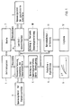
- Figure 1 shows a flow diagram for the method for monitoring the fatigue of components in a nuclear power plant.
- the basis for the fatigue analysis is the material-specific, empirically determined fatigue curve, e.g. B.
- Fig. 2 shows.
- the individual reference stress ranges ⁇ v are assigned the maximum permissible number N of load changes.
- the material fatigue caused by n equal load change fluctuations is determined by the "utilization factor" expressed.
- the total utilization factor Ug of formula gives it j as the sum of the individual partial utilization factors U according to
- n in each case, based on the associated reference stress change ⁇ i , the number of load changes actually occurring, and N ; the maximum number of load changes resulting from the curve according to FIG. 2.
- the temperatures are measured using suitable sensors (13), which in the example are arranged on a pipe section (14).
- the monitoring device according to the invention makes use of a particularly simple calculation of the voltage distribution, which is therefore described in detail below:
- the invention makes use of this superposition principle in that it approximates complex temperature profiles from elementary triangular temperature profiles, so-called “elementary transients”, according to a modular principle.
- An attempt is made to present the externally measured temperature curve R (boundary condition) as a superposition of appropriately weighted elementary transients T l l ... T n '(FIG. 6) of the inner surface surface temperatures R of the inner surface, ie The temperature field T belonging to the surface temperature R is then approximately through given.
- the elementary transients T i which are used here are due to the temperature profile occurring on the inside of the corresponding component (for example a pipe section (14) according to FIG. 3) defined as shown in Figs. 4 and 5.
- i denotes the point on the inside opposite the measuring point i
- E (I) the temperature profile on the inside
- (x, t) the dependence on the coordinates of place and time.
- FIG. 6 shows how a uniform, piece-wise linear internal temperature curve T (I) (represented by a continuous line), by means of superposition, elementary transients shifted in time and differently weighted
- T j (1) , T 2 (I) , T3 (I) , T 4 (I) can be obtained, the courses of which have the shape of simple triangles on the inside, as shown in FIG. 4.
- the “response” to an elementary transient T E (I) at point x on the inside of a component is the temperature curve E (A) according to FIG. 8 in the opposite Point y on the outside, and by superposition of the “answers” T 1 (A) -T 4 (A) according to FIG. 9, an “answer” to the temperature profile according to FIG.
- the temperature-backward analysis mentioned uses a measured outside temperature curve to determine the corresponding inside temperature curve according to the following scheme:
- the outside temperature T (A) is approximately represented as a superposition of answers E i (A), i.e. of elementary curves or elementary transients for the outer surface at location i :
- the measured curve of the outside temperature would be replaced by a large number of overlapping, time-shifted and differently weighted triangular element temperature curves.
- the individual weightings r j are determined in such a way that the best possible approximation to the actually measured profile of the outside temperature is achieved.
- Equation (8) can be described as follows:
- D is a linear differential operator. As is known, this system can be uniquely solved with given displacements or given forces in the peripheral area, taking into account the body balance conditions.
- weightings of the individual elementary transients determined in the temperature backward analysis explained with reference to FIGS. 4 to 9 can also be used directly when the individual voltage profiles are superimposed.
- the relevant weighting factors for the individual temperature transients determined in the temperature backward analysis are determined in block 2 in accordance with the flow diagram shown in FIG. 1.
- the elementary reference stress curves corresponding to the elementary transients T of the temperature of the inner surface are stored in the block-specific stress file for unit load cases, block 3 in FIG. 1. From this voltage file for unit load cases, the reference voltage curves stored for the respective temperature transient, specific to the module, are called up and multiplied in block 2 by the associated weighting factors. In block 4, the elementary voltage curves called up in the voltage file 3 and weighted in block 2 are followed by Superposition of the actual voltage curve determined.
- the degree of utilization is calculated in block 5 with the aid of a specific algorithm.
- This algorithm is known as the "rainflow" or reservoir algorithm. It is essentially based on the fact that the determined voltage curve is broken down into a finite number of simple-period processes. (See K. Roik, lectures on steel construction, Wilhelm Ernst and Son Verlag, 1978, p. 69). A material-dependent partial utilization factor is stored in a memory FAT for each of these processes.
- the partial utilization factor U to be applied for the individual periodic elementary cycle is then obtained in block 5 using the rainflow algorithm ; , which is included in the determination of the total utilization factor according to equation (2).
- the result is the cumulative time profile of the overall degree of utilization, which is transferred to peripheral devices.
- the part of the fatigue monitoring of a certain component described up to now by continuously updating the degree of utilization can be summarized as follows: On the basis of the measurement data that record the outside temperatures, the internal temperatures are first calculated back; the internal temperature curve is broken down into weighted "elementary transients". The individual elementary transients obtained when the temperature profile is divided are individually assigned voltage transients previously calculated from a file and superimposed on a voltage profile. From the superposed stress curve, partial degrees of utilization and the degree of utilization are calculated from the rainflow method using predefined fatigue curves. The replacement of the monitored component can be planned in good time before the overall degree of utilization reaches its highest permissible limit, namely the value 1.
- the corresponding load cases are identified in block 8 on the basis of various system-specific operating signals, which can essentially be seen in the control room 7 in the exemplary embodiment of a nuclear power plant 1.
- Such typical load cases are e.g. For example: slow start-up, rapid shutdown, etc.
- the voltage file shown in block 9 contains the corresponding reference voltage curves. This means: For each load case identified on the basis of certain operating signals or operating signal combinations, the associated voltages are taken from block 9 from the voltage file and compiled in block 10 to form a voltage curve.
- the data that are stored in the voltage file in block 9 have been determined on the basis of theoretical considerations and / or calculations, or have been measured in the past for special load cases. It is a matter of previously known - calculated or measured - voltage profiles for special load cases, from which the voltage profile is composed in block 10.
- the flow of information leads again from block 10 to block 5, where the associated partial utilization rate is calculated from this comparison voltage curve with the aid of the rainflow or reservoir algorithm.
- the calculation of the degree of partial utilization in block 5 by way of blocks 7 to 10, i.e. based on the load case identification and the voltage data determined for identified load cases based on previous processes and / or calculations, thus runs in parallel with the determination of the degree of utilization via the component to be monitored directly measured temperature and other mechanical data and their processing in blocks 2 to 5.
- the operating data are recorded in a block 11 and stored in a data memory, a so-called log book, indicated by block 12 in FIG. 1.
- a data memory a so-called log book, indicated by block 12 in FIG. 1.
- the results of the calculation of the stress distribution in block 4 and the formation of the stress curve in block 10 are continuously compared on the basis of the load case identification in block 8 and that the most unfavorable value is used to determine the degree of utilization to ensure maximum security. This makes it possible to determine the superimposition of voltages for the monitored modules that occurs during certain load cases that can be identified in the load case.
- the data determined in this way can be used to obtain data for module-related, life-extending operating modes of the system.
- the measured values relevant to the subject of the application come from three different sources in a nuclear power plant, namely the temperature sensors 13, 20, the mechanical sensors 15, 21 and the sensors 22, the control room 7, from which the nuclear power plant 1 is controlled.
- the temperature sensors 13, 20 provide the measured values which are required for the temperature backward analysis described above.
- the mechanical sensors 15, 21 stand for such signal transmitters or sensors, which allow information about mechanical stresses, such as. B. measuring instruments for internal pressure, flow rate, level indicators etc.
- the operating signals emanating from the sensors 22 of the control room 7 can be used to determine the current operating state (load case) of the operating system 1 or power plant.
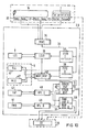
- a first memory FIFO I 37 First In / First Out
- a second memory FIFO II 38 are connected to the unit for measured value acquisition MWE 34 via a data bus 36.
- the data that is first read in time is also read out first in time.
- the memories 37, 38 are buffer memories.
- the first memory 37 is in alternating connection with the computing unit LCID 39 (load case identification), which is used to identify the individual load cases.
- the basis for the identification of the individual load cases are the operating signals coming from the sensors 22 of the control room 7.
- the computing unit LCID 39 determines, based on the load cases identified in this way, from the voltage file for specified load cases LCL 9, comparison voltage values for identified load cases, and component-dependent as well as various weighting factors for these comparison voltage values, which are determined by various sensors, and places them in one of the computing units HSP / VSP 40 for later superposition not represented RAM.
- the temperature and voltage measurement values prepared by the measurement value acquisition MWE 34 go directly to the second memory FIFO II 38 and from there to the voltage file for unit load cases 3, which contains the memory TLL (Thermal Load Library) 41 for thermal load cases and the memory MLL 42 (Mechanical Load Library) for mechanical load cases.
- TLL Thermal Load Library
- MLL 42 Mechanism Load Library
- the computing unit VSP 40 determines the resulting voltage curve by superimposing it and stores it in the STACK HSP VSP 43 memory. This is divided into two storage units 44 and 45 for the main voltages (HSP) and the determined reference voltages (VSP).
- the resulting reference stress curve stored in the memory unit 44 of the working memory STACK HSP VSP 43 is calculated in the third arithmetic unit RFL (rainflow) 46 with the aid of the material-related fatigue curves (cf. FIG. 2) stored in the memory FAT (fatigue) 47 with the rainflow mentioned above. or reservoir algorithm processed.
- the resulting partial utilization levels are added to the utilization level already stored in the RAM USE I 48 memory.
- the crack growth can be calculated.
- these main stresses occurring in the arithmetic unit HSP / VSP are stored in the memory unit STACK HSP 44 of the memory STACK HSP / VSP 43 and retrieved from there by a second arithmetic unit RFL 11 and processed on the basis of the stress-dependent crack growth curves stored in the memory RWK 50.
- the calculation result, the crack growth per load unit is added to the crack lengths previously stored in RAM USE II 51.
- the process computer 30 is connected to the console CO 35, which has the usual peripheral devices (printer, writer, etc.) and can be read in the degree of utilization and the accumulated crack lengths.
- the console 35 which is usually in the control room 7, allows the replacement of components that have been used in foreseeable periods to be planned in good time. It also enables the operating system to be operated in the way that is most gentle on the most vulnerable or most worn components.
Claims (8)
Applications Claiming Priority (2)
| Application Number | Priority Date | Filing Date | Title |
|---|---|---|---|
| DE19833314181 DE3314181A1 (de) | 1983-04-19 | 1983-04-19 | Verfahren zur ueberwachung der ermuedung von bauteilen, z.b. in kernkraftwerken |
| DE3314181 | 1983-04-19 |
Publications (3)
| Publication Number | Publication Date |
|---|---|
| EP0122578A2 EP0122578A2 (fr) | 1984-10-24 |
| EP0122578A3 EP0122578A3 (en) | 1987-04-01 |
| EP0122578B1 true EP0122578B1 (fr) | 1989-07-19 |
Family
ID=6196794
Family Applications (1)
| Application Number | Title | Priority Date | Filing Date |
|---|---|---|---|
| EP84103962A Expired EP0122578B1 (fr) | 1983-04-19 | 1984-04-09 | Méthode de surveilalnce de fatigue d'éléments par exemple dans une centrale atomique |
Country Status (6)
| Country | Link |
|---|---|
| US (1) | US4764882A (fr) |
| EP (1) | EP0122578B1 (fr) |
| JP (1) | JPS59206751A (fr) |
| BR (1) | BR8401842A (fr) |
| DE (2) | DE3314181A1 (fr) |
| ES (1) | ES8703028A1 (fr) |
Families Citing this family (47)
| Publication number | Priority date | Publication date | Assignee | Title |
|---|---|---|---|---|
| DE3505818A1 (de) * | 1985-02-20 | 1986-08-21 | Licentia Patent-Verwaltungs-Gmbh, 6000 Frankfurt | Ueberwachungs- und kontrolleinrichtung fuer schaltgeraete |
| US4801421A (en) * | 1985-06-04 | 1989-01-31 | Westinghouse Electric Corp. | On-line monitoring and analysis of reactor vessel integrity |
| US4876058A (en) * | 1987-10-05 | 1989-10-24 | Westinghouse Electric Corp. | Nuclear power generating station equipment qualification method and apparatus |
| US4926342A (en) * | 1987-12-31 | 1990-05-15 | Westinghouse Electric Corp. | High pressure rotor stress damage accumulating method |
| US4852397A (en) * | 1988-01-15 | 1989-08-01 | Haggag Fahmy M | Field indentation microprobe for structural integrity evaluation |
| US4864867A (en) * | 1988-01-19 | 1989-09-12 | Battelle Development Corporation | Determining fracture mode transition behavior of solid materials using miniature specimens |
| US4894787A (en) * | 1988-04-28 | 1990-01-16 | Kaman Aerospace Corporation | Automatic load monitoring system with remote sensing |
| US5140528A (en) * | 1988-06-13 | 1992-08-18 | Westinghouse Electric Corp. | Method for evaluating relationship between the size of discontinuity indications from non-destructive examination of a turbine rotor, stress applied to the rotor and remaining life of the rotor |
| GB2220280B (en) * | 1988-07-04 | 1992-10-21 | Rolls Royce & Ass | A control system for industrial plant |
| US4935195A (en) * | 1988-08-29 | 1990-06-19 | Westinghouse Electric Corp. | Corrosion-erosion trend monitoring and diagnostic system |
| US5157619A (en) * | 1988-10-31 | 1992-10-20 | Westinghouse Electric Corp. | Abnormal thermal loading effects monitoring system |
| DE4008560C2 (de) * | 1989-03-17 | 1995-11-02 | Hitachi Ltd | Verfahren und Vorrichtung zum Bestimmen einer Restlebensdauer eines Aggregats |
| US5163011A (en) * | 1990-09-27 | 1992-11-10 | Kaman Aerospace Corporation | Real time load monitoring system with remote sensing |
| SE468024B (sv) * | 1991-02-19 | 1992-10-19 | Asea Atom Ab | Anordning foer materialprovning i kaernreaktor |
| DE4290947T1 (fr) * | 1991-04-08 | 1993-04-01 | Hitachi, Ltd., Tokio/Tokyo, Jp | |
| CH686378A5 (de) * | 1992-10-12 | 1996-03-15 | Rieter Ag Maschf | Maschinenverwaltungssystem. |
| US5359516A (en) * | 1993-09-16 | 1994-10-25 | Schwing America, Inc. | Load monitoring system for booms |
| WO1996013764A1 (fr) * | 1994-10-26 | 1996-05-09 | Siemens Aktiengesellschaft | Procede d'analyse d'une valeur mesuree et analyseur de valeur mesuree pour la mise en ×uvre de ce procede |
| US5616866A (en) * | 1995-09-19 | 1997-04-01 | Jeol Ltd. | Method of finding stress distribution from temperature variation pattern on surface of elastic body |
| US5761086A (en) * | 1996-02-13 | 1998-06-02 | Westinghouse Electric Corporation | Apparatus and method for monitoring pressure-temperature margins |
| DE19711107C2 (de) * | 1997-03-06 | 2003-12-18 | Vattenfall Europe Generation | Verfahren zur Ermittlung von Werkstoffschädigungen an einem rotierenden thermisch und dynamisch hochbeanspruchten Maschinenteil |
| US6449565B1 (en) * | 1999-04-05 | 2002-09-10 | United Technologies Corporation | Method and apparatus for determining in real-time the fatigue life of a structure |
| FI107193B (fi) * | 1999-06-03 | 2001-06-15 | Rouvari Oy R | Mittausanturi |
| DE19944435B4 (de) * | 1999-09-16 | 2009-12-24 | Volkswagen Ag | Auswertungsverfahren zur Bestimmung des Schädigungsgrades einer Maschine oder Maschinenkomponente |
| FI20000325A0 (fi) * | 2000-02-15 | 2000-02-15 | Koivisto Marja Liisa | Menetelmä rakenteen rasituksen määrittämiseksi |
| DE10060706A1 (de) * | 2000-12-07 | 2002-06-13 | Flowtec Ag | Verfahren und eine Vorrichtung zur System- und/oder Prozeßüberwachung |
| TWI225836B (en) * | 2002-02-20 | 2005-01-01 | Sanyo Electric Co | Medicine supply apparatus |
| US20030171879A1 (en) * | 2002-03-08 | 2003-09-11 | Pittalwala Shabbir H. | System and method to accomplish pipeline reliability |
| US20050102668A1 (en) * | 2002-03-18 | 2005-05-12 | Siemens Aktiengesellschaft | Method and device for representing the dependencies of components of a technical installation |
| US6694742B2 (en) * | 2002-06-26 | 2004-02-24 | General Electric Company | Gas turbine system operation based on estimated stress |
| JP3778886B2 (ja) * | 2002-10-24 | 2006-05-24 | 本田技研工業株式会社 | 疲労安全率検査装置及び疲労安全率検査方法 |
| BRPI0415352B1 (pt) * | 2003-10-17 | 2017-05-23 | Hydralift Amclyde Inc | sistema e método baseado em computador para administrar componentes substituíveis para equipamento tendo uma pluralidade de componentes, e, método usado para monitorar a condição de equipamento remoto tendo pelo menos um componente de desgaste |
| US20050273277A1 (en) * | 2004-01-14 | 2005-12-08 | University Of Tennessee Research Foundation, Inc. | Vehicle fatigue life and durability monitoring system and methodology |
| US7171314B2 (en) * | 2004-09-30 | 2007-01-30 | The Boeing Company | Methods and systems for analyzing structural test data |
| US7467070B2 (en) * | 2004-10-26 | 2008-12-16 | Meyer Eric S | Methods and systems for modeling stress intensity solutions for integrally stiffened panels |
| EP1653050A1 (fr) * | 2004-10-29 | 2006-05-03 | Siemens Aktiengesellschaft | Procédé pour déterminer une valeur caractéristique réfléchissant l'état de fatigue d'un composant |
| CN1329689C (zh) * | 2004-10-31 | 2007-08-01 | 浙江大学 | 压力容器疲劳寿命安全预测方法 |
| EP1906273A1 (fr) * | 2006-09-29 | 2008-04-02 | Siemens Aktiengesellschaft | Procédé destiné au fonctionnement d'une installation à l'échelon industriel tout comme système de gestion d'une installation à l'échelon industriel |
| US8229681B2 (en) * | 2007-03-20 | 2012-07-24 | Exxonmobil Upstream Research Company | Method to measure tearing resistance |
| JP4202400B1 (ja) * | 2007-07-27 | 2008-12-24 | 三菱重工業株式会社 | き裂進展予測方法及びプログラム |
| CN101373495B (zh) * | 2007-08-24 | 2010-09-29 | 西门子公司 | 使用寿命终点判定及当前历史使用寿命估计的方法和系统 |
| US9645041B2 (en) | 2012-02-06 | 2017-05-09 | Endurica Llc | Interpolation engine for analysis of time-varying load data signals |
| CN104464851B (zh) * | 2014-12-19 | 2016-08-17 | 大连理工大学 | 一种用于核电站一回路高温管道热疲劳原型的监测方法 |
| CN109979622B (zh) * | 2017-12-27 | 2021-02-09 | 核动力运行研究所 | 核电厂稳压器疲劳寿命在线监测评估系统与方法 |
| JP7272785B2 (ja) * | 2018-12-05 | 2023-05-12 | ナブテスコ株式会社 | 疲労度算出装置、疲労度算出方法、アクチュエータ、アクチュエータ制御装置および航空機 |
| CN111578984B (zh) * | 2020-04-17 | 2022-07-29 | 中铁建工集团有限公司 | 一种严寒地区站房全生命周期钢结构受力状态监测系统 |
| EP4231192A1 (fr) * | 2020-10-26 | 2023-08-23 | Siemens Energy Global GmbH & Co. KG | Procédé et appareil de détermination de fatigue oligocyclique de composant mécanique, et support de stockage |
Family Cites Families (29)
| Publication number | Priority date | Publication date | Assignee | Title |
|---|---|---|---|---|
| US31750A (en) * | 1861-03-19 | Fastening fob | ||
| DE1404453U (fr) * | ||||
| DE1025898B (de) * | 1956-03-03 | 1958-03-13 | Bbc Brown Boveri & Cie | Einrichtung zur UEberwachung der Gehaeusewandtemperatur beim Anfahren von Dampf- oder Gasturbinen |
| DE1698476B1 (de) * | 1961-02-16 | 1969-12-11 | Bbc Brown Boveri & Cie | Verfahren und Einrichtung zur UEberwachung der Zustandsaenderungen von Waermekraftmaschinen |
| DE1901226A1 (de) * | 1968-01-15 | 1969-09-04 | Smiths Industries Ltd | Geraet zur Lebensdaueranzeige fuer ein Triebwerk |
| US3588265A (en) * | 1968-04-19 | 1971-06-28 | Westinghouse Electric Corp | System and method for providing steam turbine operation with improved dynamics |
| DE1958257C3 (de) * | 1969-11-20 | 1974-08-15 | Pietzsch, Ludwig, Dr.-Ing., 7500 Karlsruhe | Verfahren zur Lebensdauerüberwachung von dauerwechselbeanspruchten Maschinenoder Bauteilen und Vorrichtung zur Durchführung des Verfahrens |
| DE2151661B2 (de) * | 1971-10-16 | 1975-10-09 | Kraftwerk Union Ag, 4330 Muelheim | Einrichtung zur Ermittlung der thermischen Beanspruchung einer Turbinenwelle |
| DE2314954C3 (de) * | 1973-03-26 | 1982-08-26 | Brown, Boveri & Cie Ag, 6800 Mannheim | Anordnung zur laufenden Ermittlung und Überwachung der Lebensdauer von thermisch belasteten dickwandigen Bauelementen |
| US4330367A (en) * | 1973-05-22 | 1982-05-18 | Combustion Engineering, Inc. | System and process for the control of a nuclear power system |
| GB1513428A (en) * | 1975-06-18 | 1978-06-07 | Rolls Royce | Device for indicating the expended life of a rotating machine |
| FR2363095A1 (fr) * | 1976-08-24 | 1978-03-24 | Sfim | Appareil de mesure de l'etat de fatigue d'une piece |
| US4046002A (en) * | 1976-11-02 | 1977-09-06 | General Electric Company | Method and apparatus for determining rotor life expended |
| US4184205A (en) * | 1977-11-25 | 1980-01-15 | Ird Mechanalysis, Inc. | Data acquisition system |
| SE413438B (sv) * | 1978-08-30 | 1980-05-27 | Stangakonsult | Sett och anordning for utforande av settet att bestemma ett materials minsta belastningsomfang for spricktillvext, det vill sega dess troskelverde vid utmattning |
| US4179940A (en) * | 1978-10-02 | 1979-12-25 | Conoco, Inc. | Structural failure detection method |
| US4213183A (en) * | 1979-03-22 | 1980-07-15 | Adaptronics, Inc. | System for nondestructive evaluation of material flaw characteristics |
| DE2936882C2 (de) * | 1979-09-12 | 1985-03-21 | Kraftwerk Union AG, 4330 Mülheim | Prüfeinrichtung zur Feststellung und Analyse von Materialfehlern |
| JPS5764141A (en) * | 1980-10-07 | 1982-04-19 | Hitachi Ltd | Method and device for foreseening life of apparatus consisting of metallic structure |
| JPS5794627A (en) * | 1980-12-05 | 1982-06-12 | Komatsu Ltd | Stress distribution measuring instrument |
| US4421716A (en) * | 1980-12-29 | 1983-12-20 | S. Levy, Inc. | Safety monitoring and reactor transient interpreter |
| US4411858A (en) * | 1981-01-30 | 1983-10-25 | Scandpower, Inc. | Power performance monitoring system for nuclear reactor fuel core |
| JPS57166541A (en) * | 1981-04-08 | 1982-10-14 | Hitachi Ltd | Method and device estimating life of fluid receptacle at high temperature |
| GB2103801B (en) * | 1981-08-04 | 1985-05-22 | British Gas Corp | Assessing lifetime of duct by measuring fluid pressure and temperature within the duct |
| DE3133222A1 (de) * | 1981-08-21 | 1983-03-03 | Kraftwerk Union AG, 4330 Mülheim | Verfahren zur ermittlung des augenblicklichen und des zukuenftigen zustandes eines technischen prozesses mit hilfe von nichtlinearen prozessmodellen |
| DE3276265D1 (en) * | 1981-09-10 | 1987-06-11 | Hoesch Ag | Method for determining defects in welds |
| FR2519464A1 (fr) * | 1981-12-31 | 1983-07-08 | Framatome Sa | Procede de surveillance d'une centrale de production d'electricite equipee d'un reacteur nucleaire |
| US4459259A (en) * | 1982-06-29 | 1984-07-10 | The United States Of America As Represented By The United States Department Of Energy | Digital computer operation of a nuclear reactor |
| US4524622A (en) * | 1982-07-20 | 1985-06-25 | Kabushiki Kaisha Kobe Seiko Sho | Method and apparatus of ultrasonic flaw detection |
-
1983
- 1983-04-19 DE DE19833314181 patent/DE3314181A1/de not_active Withdrawn
-
1984
- 1984-04-09 DE DE8484103962T patent/DE3479064D1/de not_active Expired
- 1984-04-09 EP EP84103962A patent/EP0122578B1/fr not_active Expired
- 1984-04-18 BR BR8401842A patent/BR8401842A/pt unknown
- 1984-04-18 US US06/601,643 patent/US4764882A/en not_active Expired - Fee Related
- 1984-04-18 ES ES531767A patent/ES8703028A1/es not_active Expired
- 1984-04-18 JP JP59078295A patent/JPS59206751A/ja active Pending
Also Published As
| Publication number | Publication date |
|---|---|
| EP0122578A2 (fr) | 1984-10-24 |
| ES531767A0 (es) | 1987-01-16 |
| US4764882A (en) | 1988-08-16 |
| ES8703028A1 (es) | 1987-01-16 |
| BR8401842A (pt) | 1984-11-27 |
| EP0122578A3 (en) | 1987-04-01 |
| DE3314181A1 (de) | 1984-10-25 |
| DE3479064D1 (en) | 1989-08-24 |
| JPS59206751A (ja) | 1984-11-22 |
Similar Documents
| Publication | Publication Date | Title |
|---|---|---|
| EP0122578B1 (fr) | Méthode de surveilalnce de fatigue d'éléments par exemple dans une centrale atomique | |
| DE10297609B4 (de) | Verfahren und System zum Senden von lokalisierungs- und identitätsabhängiger Information an mobile Endgeräte | |
| DE69910800T2 (de) | Verfahren und Vorrichtung zur Überwachung des Betriebszustandes einer einzelnen Maschine | |
| DE2500086A1 (de) | Diagnostisches verbindungssystem fuer computergesteuerte werkzeugmaschinen | |
| DE3336245A1 (de) | Verfahren zum ermitteln einer leckstelle an druckfuehrenden behaeltern und einrichtung dazu | |
| DE112016006264T5 (de) | Anomalie-Detektionseinrichtung und Anomalie-Detektionssystem | |
| EP2901538B1 (fr) | Procédé et système d'exploitation d'un réseau d'alimentation en énergie électrique | |
| EP2067080B1 (fr) | Procédé pour faire fonctionner une installation industrielle, et système de guidage correspondant | |
| EP3599583A1 (fr) | Détermination de la consommation de l'énergie de chauffage ou de refroidissement d'une sous-unité de construction | |
| CH643674A5 (de) | Sicherheits-einrichtung fuer einen kernreaktor. | |
| EP2162810B1 (fr) | Procédé pour déterminer la longévité d'un élément de centrale électrique | |
| DE4217007A1 (de) | Verfahren und Vorrichtung zur Überwachung und Sicherung der Produktqualität | |
| DE102018213705A1 (de) | Verfahren zum Berechnen von elektrischen Leistungstransfers für einen lokalen Energiemarkt sowie lokaler Energiemarkt | |
| DE102020125218A1 (de) | Diagnosegerät | |
| DE102019134113A1 (de) | Datensortiervorrichtung und datensortierverfahren und überwachungs- und diagnosevorrichtung | |
| EP1598717A2 (fr) | Procédé de surveillance d'une pluralité des installations de gaz | |
| DE102019207059A1 (de) | Verfahren zur Validierung von Systemparametern eines Energiesystems, Verfahren zum Betrieb eines Energiesystems sowie Energiemanagementsystem für ein Energiesystem | |
| DE102018110044B4 (de) | Verfahren und Vorrichtung zum aufeinander abgestimmten Betreiben von elektrischen Einrichtungen | |
| DE102021203001B4 (de) | Verfahren zum Betrieb einer Heizkostenverteilervorrichtung und Heizkostenverteilervorrichtung | |
| DE102019215262A1 (de) | Verfahren zur Parameteridentifikation eines Black-Box-Modells für eine oder mehrere energietechnische Anlagen eines Energiesystems | |
| DE102022101000A1 (de) | Verfahren zum Erzeugen einer CAM-orientierten Zeit-Spline-Kurve und -Oberfläche | |
| EP4345466A1 (fr) | Appareil de commande et procédé de surveillance d'un consommateur | |
| WO2020244939A1 (fr) | Procédé de détermination de l'état d'une unité d'entraînement pour un dispositif de commutation haute ou moyenne tension et dispositif de commutation haute ou moyenne tension | |
| DE4421244C2 (de) | Einrichtung und Verfahren zur Generierung von virtuellen Meßdaten | |
| EP0599438A2 (fr) | Procédé et dispositif pour la surveillance de signaux de tension périodiques |
Legal Events
| Date | Code | Title | Description |
|---|---|---|---|
| PUAI | Public reference made under article 153(3) epc to a published international application that has entered the european phase |
Free format text: ORIGINAL CODE: 0009012 |
|
| AK | Designated contracting states |
Designated state(s): BE DE FR IT SE |
|
| PUAL | Search report despatched |
Free format text: ORIGINAL CODE: 0009013 |
|
| AK | Designated contracting states |
Kind code of ref document: A3 Designated state(s): BE DE FR IT SE |
|
| 17P | Request for examination filed |
Effective date: 19870216 |
|
| RAP1 | Party data changed (applicant data changed or rights of an application transferred) |
Owner name: SIEMENS AKTIENGESELLSCHAFT BERLIN UND MUENCHEN |
|
| 17Q | First examination report despatched |
Effective date: 19880926 |
|
| GRAA | (expected) grant |
Free format text: ORIGINAL CODE: 0009210 |
|
| AK | Designated contracting states |
Kind code of ref document: B1 Designated state(s): BE DE FR IT SE |
|
| REF | Corresponds to: |
Ref document number: 3479064 Country of ref document: DE Date of ref document: 19890824 |
|
| ET | Fr: translation filed | ||
| ITF | It: translation for a ep patent filed |
Owner name: STUDIO JAUMANN |
|
| PLBE | No opposition filed within time limit |
Free format text: ORIGINAL CODE: 0009261 |
|
| STAA | Information on the status of an ep patent application or granted ep patent |
Free format text: STATUS: NO OPPOSITION FILED WITHIN TIME LIMIT |
|
| 26N | No opposition filed | ||
| ITTA | It: last paid annual fee | ||
| PGFP | Annual fee paid to national office [announced via postgrant information from national office to epo] |
Ref country code: FR Payment date: 19920428 Year of fee payment: 9 |
|
| PG25 | Lapsed in a contracting state [announced via postgrant information from national office to epo] |
Ref country code: FR Effective date: 19931229 |
|
| REG | Reference to a national code |
Ref country code: FR Ref legal event code: ST |
|
| EAL | Se: european patent in force in sweden |
Ref document number: 84103962.1 |
|
| PGFP | Annual fee paid to national office [announced via postgrant information from national office to epo] |
Ref country code: BE Payment date: 19970410 Year of fee payment: 14 |
|
| PGFP | Annual fee paid to national office [announced via postgrant information from national office to epo] |
Ref country code: SE Payment date: 19970421 Year of fee payment: 14 |
|
| PGFP | Annual fee paid to national office [announced via postgrant information from national office to epo] |
Ref country code: DE Payment date: 19970617 Year of fee payment: 14 |
|
| PG25 | Lapsed in a contracting state [announced via postgrant information from national office to epo] |
Ref country code: SE Free format text: LAPSE BECAUSE OF NON-PAYMENT OF DUE FEES Effective date: 19980410 |
|
| PG25 | Lapsed in a contracting state [announced via postgrant information from national office to epo] |
Ref country code: BE Free format text: LAPSE BECAUSE OF NON-PAYMENT OF DUE FEES Effective date: 19980430 |
|
| BERE | Be: lapsed |
Owner name: SIEMENS A.G. BERLIN UND MUNCHEN Effective date: 19980430 |
|
| EUG | Se: european patent has lapsed |
Ref document number: 84103962.1 |
|
| PG25 | Lapsed in a contracting state [announced via postgrant information from national office to epo] |
Ref country code: DE Free format text: LAPSE BECAUSE OF NON-PAYMENT OF DUE FEES Effective date: 19990202 |