EP0122030A1 - A magnetic recording member and a manufacturing method for such a member - Google Patents
A magnetic recording member and a manufacturing method for such a member Download PDFInfo
- Publication number
- EP0122030A1 EP0122030A1 EP84301530A EP84301530A EP0122030A1 EP 0122030 A1 EP0122030 A1 EP 0122030A1 EP 84301530 A EP84301530 A EP 84301530A EP 84301530 A EP84301530 A EP 84301530A EP 0122030 A1 EP0122030 A1 EP 0122030A1
- Authority
- EP
- European Patent Office
- Prior art keywords
- magnetic
- substrate
- incidence
- metal
- substantially perpendicular
- Prior art date
- Legal status (The legal status is an assumption and is not a legal conclusion. Google has not performed a legal analysis and makes no representation as to the accuracy of the status listed.)
- Granted
Links
- 230000005291 magnetic effect Effects 0.000 title claims abstract description 282
- 238000004519 manufacturing process Methods 0.000 title claims abstract description 55
- 239000000758 substrate Substances 0.000 claims abstract description 119
- 229910052751 metal Inorganic materials 0.000 claims abstract description 83
- 239000002184 metal Substances 0.000 claims abstract description 83
- 239000000203 mixture Substances 0.000 claims abstract description 76
- 229910052760 oxygen Inorganic materials 0.000 claims abstract description 19
- QVGXLLKOCUKJST-UHFFFAOYSA-N atomic oxygen Chemical compound [O] QVGXLLKOCUKJST-UHFFFAOYSA-N 0.000 claims abstract description 17
- 239000001301 oxygen Substances 0.000 claims abstract description 17
- 238000009489 vacuum treatment Methods 0.000 claims abstract description 16
- 230000005294 ferromagnetic effect Effects 0.000 claims abstract description 12
- MYMOFIZGZYHOMD-UHFFFAOYSA-N Dioxygen Chemical compound O=O MYMOFIZGZYHOMD-UHFFFAOYSA-N 0.000 claims abstract description 10
- 229910001882 dioxygen Inorganic materials 0.000 claims abstract description 10
- 239000000696 magnetic material Substances 0.000 claims abstract description 10
- 239000011247 coating layer Substances 0.000 claims abstract description 7
- 150000002739 metals Chemical class 0.000 claims abstract description 6
- 229910001004 magnetic alloy Inorganic materials 0.000 claims abstract description 4
- 230000008021 deposition Effects 0.000 claims description 28
- 239000007789 gas Substances 0.000 claims description 24
- 239000010419 fine particle Substances 0.000 claims description 5
- 239000002245 particle Substances 0.000 claims description 5
- 230000005672 electromagnetic field Effects 0.000 claims description 3
- 238000010438 heat treatment Methods 0.000 abstract description 11
- 238000010894 electron beam technology Methods 0.000 abstract description 8
- 238000001816 cooling Methods 0.000 abstract description 2
- 238000005566 electron beam evaporation Methods 0.000 abstract description 2
- 239000010408 film Substances 0.000 description 149
- 125000004429 atom Chemical group 0.000 description 43
- 238000001704 evaporation Methods 0.000 description 27
- 238000000151 deposition Methods 0.000 description 26
- 238000000034 method Methods 0.000 description 26
- 230000008020 evaporation Effects 0.000 description 22
- 230000001133 acceleration Effects 0.000 description 19
- 230000008569 process Effects 0.000 description 16
- 229910020647 Co-O Inorganic materials 0.000 description 14
- 229910020704 Co—O Inorganic materials 0.000 description 14
- 229910018553 Ni—O Inorganic materials 0.000 description 14
- 238000004544 sputter deposition Methods 0.000 description 12
- 229910020630 Co Ni Inorganic materials 0.000 description 10
- 229910002440 Co–Ni Inorganic materials 0.000 description 10
- 230000005415 magnetization Effects 0.000 description 9
- 238000010586 diagram Methods 0.000 description 8
- 125000004430 oxygen atom Chemical group O* 0.000 description 8
- 239000000463 material Substances 0.000 description 7
- 229910052759 nickel Inorganic materials 0.000 description 6
- 230000005684 electric field Effects 0.000 description 5
- 230000004907 flux Effects 0.000 description 5
- 229910045601 alloy Inorganic materials 0.000 description 4
- 239000000956 alloy Substances 0.000 description 4
- 239000013078 crystal Substances 0.000 description 4
- 229910052742 iron Inorganic materials 0.000 description 4
- 239000005020 polyethylene terephthalate Substances 0.000 description 4
- 229910052804 chromium Inorganic materials 0.000 description 3
- 230000003247 decreasing effect Effects 0.000 description 3
- 238000009792 diffusion process Methods 0.000 description 3
- 230000000694 effects Effects 0.000 description 3
- 239000002923 metal particle Substances 0.000 description 3
- 230000001590 oxidative effect Effects 0.000 description 3
- 229910000889 permalloy Inorganic materials 0.000 description 3
- 229920000139 polyethylene terephthalate Polymers 0.000 description 3
- 229910020641 Co Zr Inorganic materials 0.000 description 2
- 229910020520 Co—Zr Inorganic materials 0.000 description 2
- 229910001111 Fine metal Inorganic materials 0.000 description 2
- 230000005292 diamagnetic effect Effects 0.000 description 2
- 238000002474 experimental method Methods 0.000 description 2
- 239000010410 layer Substances 0.000 description 2
- 238000004804 winding Methods 0.000 description 2
- 229910000640 Fe alloy Inorganic materials 0.000 description 1
- 229910017709 Ni Co Inorganic materials 0.000 description 1
- 229910000990 Ni alloy Inorganic materials 0.000 description 1
- 229910003267 Ni-Co Inorganic materials 0.000 description 1
- 229910003262 Ni‐Co Inorganic materials 0.000 description 1
- 239000004642 Polyimide Substances 0.000 description 1
- 238000002441 X-ray diffraction Methods 0.000 description 1
- 230000008859 change Effects 0.000 description 1
- 238000010549 co-Evaporation Methods 0.000 description 1
- 239000011248 coating agent Substances 0.000 description 1
- 238000000576 coating method Methods 0.000 description 1
- 230000007797 corrosion Effects 0.000 description 1
- 238000005260 corrosion Methods 0.000 description 1
- 238000002425 crystallisation Methods 0.000 description 1
- 230000008025 crystallization Effects 0.000 description 1
- 230000007547 defect Effects 0.000 description 1
- 230000002950 deficient Effects 0.000 description 1
- 239000012777 electrically insulating material Substances 0.000 description 1
- 230000006872 improvement Effects 0.000 description 1
- 239000007788 liquid Substances 0.000 description 1
- 238000001755 magnetron sputter deposition Methods 0.000 description 1
- 239000007769 metal material Substances 0.000 description 1
- 238000002156 mixing Methods 0.000 description 1
- 229910052750 molybdenum Inorganic materials 0.000 description 1
- 239000004033 plastic Substances 0.000 description 1
- 229920003023 plastic Polymers 0.000 description 1
- -1 polyethylene terephthalate Polymers 0.000 description 1
- 229920001721 polyimide Polymers 0.000 description 1
- 229910052702 rhenium Inorganic materials 0.000 description 1
- 229910052703 rhodium Inorganic materials 0.000 description 1
- 230000000630 rising effect Effects 0.000 description 1
- 238000000926 separation method Methods 0.000 description 1
- 239000006104 solid solution Substances 0.000 description 1
- 239000010409 thin film Substances 0.000 description 1
- 229910052719 titanium Inorganic materials 0.000 description 1
- 229910052721 tungsten Inorganic materials 0.000 description 1
- 238000007738 vacuum evaporation Methods 0.000 description 1
- 229910052720 vanadium Inorganic materials 0.000 description 1
Images


Classifications
-
- H—ELECTRICITY
- H01—ELECTRIC ELEMENTS
- H01F—MAGNETS; INDUCTANCES; TRANSFORMERS; SELECTION OF MATERIALS FOR THEIR MAGNETIC PROPERTIES
- H01F41/00—Apparatus or processes specially adapted for manufacturing or assembling magnets, inductances or transformers; Apparatus or processes specially adapted for manufacturing materials characterised by their magnetic properties
- H01F41/14—Apparatus or processes specially adapted for manufacturing or assembling magnets, inductances or transformers; Apparatus or processes specially adapted for manufacturing materials characterised by their magnetic properties for applying magnetic films to substrates
- H01F41/20—Apparatus or processes specially adapted for manufacturing or assembling magnets, inductances or transformers; Apparatus or processes specially adapted for manufacturing materials characterised by their magnetic properties for applying magnetic films to substrates by evaporation
-
- G—PHYSICS
- G11—INFORMATION STORAGE
- G11B—INFORMATION STORAGE BASED ON RELATIVE MOVEMENT BETWEEN RECORD CARRIER AND TRANSDUCER
- G11B5/00—Recording by magnetisation or demagnetisation of a record carrier; Reproducing by magnetic means; Record carriers therefor
- G11B5/62—Record carriers characterised by the selection of the material
- G11B5/64—Record carriers characterised by the selection of the material comprising only the magnetic material without bonding agent
- G11B5/65—Record carriers characterised by the selection of the material comprising only the magnetic material without bonding agent characterised by its composition
- G11B5/658—Record carriers characterised by the selection of the material comprising only the magnetic material without bonding agent characterised by its composition containing oxygen, e.g. molecular oxygen or magnetic oxide
-
- G—PHYSICS
- G11—INFORMATION STORAGE
- G11B—INFORMATION STORAGE BASED ON RELATIVE MOVEMENT BETWEEN RECORD CARRIER AND TRANSDUCER
- G11B5/00—Recording by magnetisation or demagnetisation of a record carrier; Reproducing by magnetic means; Record carriers therefor
- G11B5/84—Processes or apparatus specially adapted for manufacturing record carriers
- G11B5/85—Coating a support with a magnetic layer by vapour deposition
-
- H—ELECTRICITY
- H01—ELECTRIC ELEMENTS
- H01F—MAGNETS; INDUCTANCES; TRANSFORMERS; SELECTION OF MATERIALS FOR THEIR MAGNETIC PROPERTIES
- H01F10/00—Thin magnetic films, e.g. of one-domain structure
- H01F10/08—Thin magnetic films, e.g. of one-domain structure characterised by magnetic layers
- H01F10/10—Thin magnetic films, e.g. of one-domain structure characterised by magnetic layers characterised by the composition
- H01F10/18—Thin magnetic films, e.g. of one-domain structure characterised by magnetic layers characterised by the composition being compounds
- H01F10/20—Ferrites
Definitions
- This invention relates to a magnetic recording member and a manufacturing method for such a member.
- a recent development known to the applicants is that of a new magnetic recording system capable of high density recording, involving a perpendicular magnetic recording system and a magneto-optical recording system.
- a magnetic film proposed for such recording systems is a so-called perpendicular-incident deposition magnetic film, which has a magnetic anisotropy in the direction perpendicular to the plane of the film and meets the required conditions of "Ku ⁇ ⁇ 2 ⁇ Ms 2 , Hc ⁇ > Hc // and Br ⁇ > Br // .
- Co has a large magnets or magnetic crystalline anisotropy in the c axial direction of an hcp structure thereof, and for obtaining a perpendicular-incident deposition magnetic film by making use of this magnetic anisotropy, it is necessary or desirable to meet such requirements that (1) the direction of the c axis thereof is substantially perpendicular to the plane of the film, and (2) that the magnetic crystalline anisotropy Ku is larger than a diamagnetic field 2 ⁇ Ms 2 generated in the perpendicular direction to the plane of the film.
- the Co film has a large value of saturation magnetization Ms, and therefore does not meet the foregoing requirement (2), so that a perpendicular-incident deposition magnetic film cannot be made of Co.
- a perpendicular-incident deposition magnetic film a Co - Cr system thin film
- this film has been made by an evaporation process.
- the evaporation process is defective in that the vapor pressures of Co and Cr are substantially different from each other, and consequently it becomes difficult to keep a uniform Cr - Co composition ratio for a long period of time during manufacture of the magnetic film.
- a uniform magnetic film having a perpendicular magnetic property can be obtained only when evaporation deposition thereof on a substrate is carried out under the condition that the substrate is heated to 200 - 300°C.
- the perpendicular-incident deposition magnetic film cannot be obtained unless the substrate is heated, and curling of a tape-shaped substrate and warping of a substrate of the floppy disk type are caused by such heat.
- a heat resisting substrate has to be used, resulting in increased production costs.
- a magnetic recording member characterized in that it comprises a substrate having formed on a surface thereof, either directly on the surface or on the intermediary of a soft magnetic material coating layer, a substantially perpendicular-incidence magnetic film comprising a composition of a magnetic metal and oxygen (Me-O), where the magnetic metal Me comprises one or more ferro-magnetic metals and/or magnetic alloys thereof.
- a magnetic metal and oxygen Me-O
- a method of manufacturing a magnetic recording member characterized in that a magnetic metal Me provided in a vacuum treatment chamber is evaporated while 0 2 gas is introduced into the chamber so that part of vapors of the magnetic metal Me may be oxidized, and the partially oxidized vapors thereof are deposited on a substrate at a substantially perpendicular incident angle to a surface of the substrate and in the course of the perpendicular incident deposition of the magnetic metal vapors, part of the vapors is ionized, and thus there is formed on the surface of the substrate a substantially perpendicular-incidence magnetic film comprising a predetermined composition of Me and 0 atoms.
- part thereof is ionized and the perpendicular incident deposition thereof on the substrate is carried out while the ionized vapors thereof are accelerated in speed by an electromagnetic field of d.c. or a.c. power.
- a manufacturing method characterized in that a target comprising a magnetic metal Me provided in a vacuum treatment chamber is sputtered under the condition that 0 2 gas is introduced into the chamber and sputtered fine particles of the magnetic metal are deposited on a surface of a substrate at substantially perpendicular incidence thereon while part of the atoms of the sputtered fine particles is oxidized, so that there is formed on the surface of the substrate a substantially perpendicular-incidence magnetic film having a predetermined composition of magnetic metal Me and 0 atoms.
- the target of the magnetic metal Me and an electrode comprising the substrate itself, or an electrode provided near the substrate, and the electrode is supplied with an electric voltage of d.c. or a.c. power, and the target is sputtered while 0 2 gas is introduced into the chamber so that innumerable sputtered magnetic metal particles are deposited on the substrate at substantially perpendicular incidence thereon, while some atoms thereof are oxidized and thus there is formed on the substrate a substantially perpendicular-incidence magnetic film comprising a predetermined composition of magnetic metal and 0 atoms.
- the substrate may be provided with a soft magnetic material coating layer on which is formed the substantially perpendicular-incidence magnetic film.
- Preferred examples of the invention may provide a perpendicular-type recording member free from the foregoing inconveniences and may be characterized in that there is formed either directly on the surface of a substrate, or with the intermediary of a soft magnetic material coating layer on the surface of the substrate, a substantially perpendicular-incident deposition magnetic film.
- the film comprises a composition of magnetic metal Me and oxygen, where the magnetic metal Me represents any one type or more selected from the magnetic metals and the magnetic alloys.
- the magnetic metal Me may include typically, but not restrictively, Fe, Co, Ni or a mixture thereof, and/or any alloy thereof.
- the soft magnetic material coating layer may be made of permalloy or an amorphous film made of Fe, Co, Co-Zr or the like.
- Preferred examples of the invention may provide a manufacturing method of the above perpendicular-type magnetic recording member and may be characterized in that while oxygen gas is introduced into a vacuum treatment chamber, a magnetic metal Me is vaporized and atomic vapors thereof are deposited on a surface of a substrate at a substantially perpendicular incident angle to the surface of the substrate.
- a perpendicular-type magnetic recording member having a perpendicular-incident deposition magnetic film comprising a composition of Co and 15 - 50 at% 0, and a manufacturing method thereof.
- Figure 1 shows a vacuum evaporation treatment apparatus for manufacturing the foregoing magnetic recording member according to the present invention.
- Numeral 1 denotes a vacuum treatment chamber, and there are provided in the chamber 1 a rotary cooling can 2 of cylindrical drum type and an electron beam evaporation source 3 comprising a crucible positioned just under the can 2.
- the chamber 1 is connected through a control valve to a vacuum pump which is not shown.
- an unwinding roller 4 and a winding roller 5 are disposed and are arranged to be rotated by a motor (not shown).
- a tape-shaped substrate a made of such non-magnetic material as a PET material is mounted on the unwinding roller 4 and is arranged to be unrolled and run at a constant speed around a circumferential surface of the water-cooled can 2, and finally to be taken-up by the winding roller 5.
- a supply pipe 6 for introducing oxygen into the chamber 1.
- a control valve may be interposed in the pipe 6 in the illustrated example, and the supply pipe 6 is made so long that its open end is located near a surface of the running tape substrate a.
- Numeral 7 denotes right and left vapor-adhesion shield plates which are so disposed as to leave a space interval 8 therebetween at a region through which the lowermost surface of the can 2 faces the evaporation source 3, so that Co atoms evaporated from the evaporation source 3 may pass through the space interval 8 and be deposited on the surface of the tape substrate a substantially perpendicular to the surface of the substrate a.
- the plate 7 may be arranged to be movable to the right or left if desired.
- Numeral 9 denotes an electron beam heating means.
- a magnetic recording member according to this invention is manufactured by using the above apparatus as follows:
- a raw ferro-magnetic metal material b to be evaporated, Co metal for instance, is evaporated at a constant rate from the evaporation source 3 by electron beam heating.
- 0 2 gas is introduced into the chamber 1 through the supply pipe 6 for oxidizing part of the Co vapors, and the partially oxidized Co vapors pass through the space 8 and are deposited on the substrate a running on the lower surface of the cooled can 2.
- the vapors are deposited substantially perpendicular or at normal incidence upon and to the substrate a, so that there is formed on the surface of the tape substrate a a perpendicular-incident deposition magnetic film comprising a composition of Co-O.
- perpendicular-type magnetic recording members having respective Co-O perpendicular-incidence magnetic films comprising various composition ratios of Co-O.
- These members also have magnetic films which vary in thickness in the range of 1000 A° - 10000 A° , caused by varying the running speed of the tape substrate a.
- magnetic properties are measured to obtain the relationships between the Co-0 composition ratios and the magnetic properties, as shown in Figures 2A, 2B, 2C.
- both a coercive force Hc ⁇ in the direction perpendicular to the film surface, and a residual magnetic flux density Br ⁇ thereof, are increased, and if the 0 content becomes above 15 atom.%, both Hc ⁇ and Br ⁇ become higher than a coercive force Hc // and a residual magnetic flux density Br // respectively, so that perpendicular deposition magnetic films can be obtained.
- a saturation magnetization value becomes zero, resulting in losing the magnetic properties of the film.
- Fig.3 shows characteristic curves of an hysteresis loop resulting from a perpendicular-incidence magnetic film comprising a typical composition of Co-36 at.% 0 , and from this Figure it is understood that this is a sufficient perpendicular-incident magnetic film.
- films having any predetermined compositions in the range of Co-15-50 at% 0, can be also manufactured by varying the evaporation rate of Co while the introduction rate of 0 2 gas is varied.
- the relationships between the two are generally proportional to the incident deposition frequencies of both the atoms upon the substrate, and therefore if the Co evaporation rate is increased, it is necessary to increase the partial pressure of 0 2 .
- the perpendicular-incident magnetic films comprising the Co-15-50 at% 0 compositions have excellent coercive force Hc ⁇ in the range of about 400 - 1000 ⁇ e, which are the best values for a perpendicular-incident magnetic film.
- a good perpendicular-type magnetic film can be obtained even in a case where the substrate is cooled, or unheated to remain at a normal temperature.
- the present methods are not therefore limited to substrates which are made of an expensive heat-resisting plastics film such as polyimide or the like.
- the present material of the substrate to be used is not limited, so that an inexpensive material having no heat-resistance such as a P ET film or the like can be also used, and a good perpendicular-type magnetic film can be obtained without heating the substrate.
- the substrate it is of course possible for the substrate to be heated if so desired.
- the Co columnar particle has not only the crystal anisotropy but also a shape anisotropy, and thereby the perpendicular magnetic anisotropy of the film is improved.
- an average saturation magnetization value is so lowered as to meet the requirement of Ku ⁇ ⁇ 2 ⁇ Ms 2 to obtain the required perpendicular magnetic film.
- the diameter of the columnar Co particle is considered to be about from several hundreds A ° to several thousands A°, and is a fine metal particle and accordingly has a high magnetic holding or coercive force.
- a minor amount of one or more other elements may be mixed in the foregoing Co-O perpendicular-incidence magnetic film.
- any element which makes a solid solution with Co and does not cause harm to the h c p structure for instance, Cr, V, Mo, W, Rh, Ti, Re etc. may be mixed therein in a minor amount.
- the perpendicular magnetic recording system a magnetic recording member having, between the perpendicular-incidence magnetic film and the non-magnetic substrate, an intermediate magnetic film formed of permalloy or an amorphous film of Fe, Co, Co-Zr that has a comparatively soft magnetic property and is large in saturation magnetization. If such an intermediate film is used, the electric current required for recording can be decreased, and also the reproduction output can be increased.
- Such a perpendicular magnetic recording member may be manufactured in such a manner that initially the intermediate magnetic film is formed on a surface of the non-magnetic substrate, and then a perpendicular-incident deposition magnetic film comprising a predetermined Co-O composition is formed on a surface of the intermediate magnetic film according to the present manufacturing methods according to the present invention.
- the intermediate magnetic film as above may be formed on one or both surfaces of the substrate and then the perpendicular magnetic film comprising a predetermined Co-O composition formed on one or both surfaces of the intermediate magnetic film.
- the Co-Ni-O composition is (Co 1-z Ni z ) 1-m O m wherein 0 ⁇ z ⁇ 0.40 and 0.15 ⁇ m ⁇ 0.50.
- a perpendicular-type magnetic recording member having a perpendicular-incidence magnetic film comprising - the foregoing Co-Ni-O composition may be manufactured using the apparatus shown in Fig.l, and almost in the same manner as the first embodiment of this invention. Namely, initially, after the interior of the chamber 1 is evacuated to be below 1 x 10" Torr, a Co-Ni alloy or a mixture of Co and Ni metals mixed in a predetermined ratio is evaporated at a constant rate by an electric beam heating means while 0 2 gas is introduced into the chamber 1 through the pipe 6.
- Partially oxidized vapors of Co and Ni are deposited on a surface of the substrate a running at a constant speed, substantially perpendicularly or normally thereto so that there is formed thereon a perpendicular-incident deposition magnetic film comprising a predetermined Co-Ni-O composition.
- perpendicular-type magnetic recording members having evaporation deposition magnetic films comprising various Co-Ni-O compositions are prepared by varying the 0 2 gas introduction rate for obtaining various 0 2 partial pressures in the chamber 1, or by varying the mixing ratio of Co to Ni to be evaporated.
- Figure 7 shows characteristic curves of an hysteresis loop of a typical perpendicular magnetic film comprising (Co 0.9 Ni 0.1 ) 0.7 o 0.3 according to the invention, and it is clear therefrom that the film is a sufficient perpendicular magnetic film.
- the O component has to be in the range of 15 - 50 at%, and the Ni component ratio of Co and Ni is 60 ⁇ Co ⁇ 1 to 0 ⁇ Ni ⁇ 40 at% perpendicular magnetic films can be obtained.
- the crystalline structure of the deposited metal grains becomes a f c c structure, and is much decreased in magnetic crystalline anisotropy, resulting in producing no perpendicular-incidence magnetic film.
- this inventive perpendicular-incidence magnetic film including the Ni material is improved in corrosion resistance.
- the perpendicular magnetic holding or coercive force of this inventive magnetic film is about 400 - 1000 ⁇ e, which are the best values for a perpendicular-type magnetic recording member.
- the substrate is cooled by the can 2, but it is not always necessary to cool the substrate. Good results also can be obtained when the substrate is not heated. When the substrate is not heated, no curling or warping thereof is brought about, resulting in a good product.
- inexpensive material can be used as the substrate.
- the aforementioned intermediate magnetic film may be interposed between the substrate and the perpendicular-incidence magnetic film of Co-Ni-O composition.
- a manufacturing method for the above magnetic recording member may be carried out by using the aforementioned apparatus 1 in almost the same manner as in the previous two examples.
- the perpendicular-incident deposition magnetic film thus obtained comprises a phase of perpendicularly grown columnar ferro-magnetic grains of Fe-Co-Ni and a phase of non-magnetic oxides thereof surrounding the columnar grains.
- the perpendicular magnetic anisotropic energy Ku is larger than the diamagnetic field energy 2 ⁇ Ms 2 in the direction perpendicular to the phase of the film.
- the perpendicular magnetic anisotropy a crystal magnetic anisotropy and a shape magnetic anisotropy can be considered.
- the perpendicular magnetic film of this example has such a structure that the ferro-magnetic column grain phase of Fe-Co-Ni grown perpendicularly is surrounded by a non-magnetic phase of oxides of Fe-Co-Ni, and also the column grain is such a long one that the diameter of its short axis is about 200 - 1000 A° and that of its long axis is about 1000 A - 1 ⁇ m, so that this example of magnetic film has also a large shape magnetic anisotropy.
- the role of the oxygen introduction is to separate the perpendicular columnar grains from each other by the non-magnetic oxides and to decrease the saturation magnetization of the entire magnetic film for satisfying the condition of K ⁇ ⁇ 2 ⁇ Ms 2 .
- the perpendicular magnetic film is obtained when the oxygen component is more than 25 at% in the A region and more than 15 at% in the B region, and effective perpendicular magnetic films can be obtained in the range of 15 to 50 at% in oxygen content in the A region and, above all, the most effective one in the range of 35 - 45 at% O.
- effective films can be obtained in the range of 15 - 50 at% in 0 2 content and the most effective one in the range of 25 - 45 at% O. Namely, if the 0 content is beyond 50 at%, it causes the saturation magnetization to become zero. This is considered to be caused due to the fact that the oxides are FeO, CoO, NiO or the mixed crystallines thereof in the automatic ratio of 1 : 1.
- the Hc ⁇ of the perpendicular magnetic films obtained by the foregoing two A,B regions added therein with the oxygen contents of the foregoing predetermined range are about 400 - 1000 ⁇ e, which are the best values for a perpendicular magnetic recording member.
- Those values are obtained by using the foregoing apparatus as shown in Fig.l and in almost the same manner as in the foregoing example cases, namely, even in a case where the substrate is not heated at a normal temperature, or in the case where it is cooled.
- the reason why good perpendicular magnetic properties can be obtained even under the condition that the substrate is not heated is considered to be due to such a fact that the 0 atoms easily diffuse or. spread over the film snrface.
- the previously proposed Co-Cr system perpendicular magnetic film is obtained with such a structure that Cr atoms are segregated around the crystal boundaries of the Co columnar grains to form non-magnetic phases separating the columnar grains from each other.
- Cr atoms are segregated around the crystal boundaries of the Co columnar grains to form non-magnetic phases separating the columnar grains from each other.
- oxygen gas is arranged to be introduced and easily diffuses over the film surface. Even in a case when the substrate is not heated, a good perpendicular-incidence magnetic film can be obtained.
- a manufacturing method for the above products is almost the same as the previous two examples.
- advantages brought about by the manufacturing method are substantially the same as those in the two previous examples. Namely, there can be obtained a uniform magnetic film for a long period of time in a continuous manufacturing operation, and no curling or warping of the product is produced.
- FIGS. 9 and 10 show the resultant values of Hc ⁇ /Hc // and Br ⁇ /Br // in the case where the 0 2 component is kept constant at 15 at% while the Fe-Co-Ni composition is varied in ratio thereof.
- Hc ⁇ /Hc // and Br ⁇ /Br // are both more than 1.
- a Hc ⁇ /Hc // is more than 1, but Br ⁇ /Br // is less than 1.
- Hc ⁇ /Hc // and Br ⁇ /Br // are both less than 1, so that no perpendicular-incidence magnetic films can be produced in the f c c phase structure.
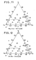
- Figs. 11 and 12 show a case including a constant content of 25 at% 0, and indicate that there are produced perpendicular-incidence magnetic films in the A and B regions.
- Figs.13 and 14 show a case including a constant content of 40 at% 0 and indicate that there are produced perpendicular-incidence magnetic films in the A and B regions.
- perpendicular magnetic recording members having the foregoing intermediate soft magnetic film interposed betweeen the substrate and the perpendicular-incidence ferromagnetic film.
- this embodiment of the foregoing manufacturing method may provide a manufacturing method for manufacturing a further improved perpendicular-type magnetic recording member, characterized in that a magnetic metal Me in a vacuum treatment chamber is vaporized while 0 2 gas is introduced into the chamber for oxidizing part of vapors of the magnetic metal Me, and the vapors thereof are deposited on a substrate at a substantially perpendicular incident onto a surface of the substrate and, in the course of the perpendicular-incident deposition of the vapors of the magnetic metal, part of the vapors is ionized, and thus there is formed thereon a perpendicular-deposition magnetic film comprising a predetermined composition of Me and 0 atoms.
- the crystallization of ferro-magnetic columnar grains is improved and the magnetic crystalline anisotropy is increased.
- lattice defects in the columnar grains or subgrains can be eliminated and orderly oriented columnar grains can be obtained, so that shape magnetic anisotropy thereof is improved.
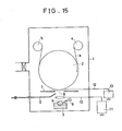
- the ionized vapors may be accelerated in speed by an electromagnetic field of d.c. or a.c. power. Examples will be explained with reference to Figs. 15 to 19.
- Fig. 15 shows an apparatus for carrying out the above manufacturing methods. The apparatus is different from the apparatus shown in Fig.l, in being-provided with the following arrangement.
- the apparatus 1 is provided with an ionizing means.
- the ionizing means comprises an electrode 10 provided in a space located above the evaporation source 3, and a d.c. power source or an RF source 11 is connected to the electrode 10.
- the electrode 10 comprises an anode which is arranged to be supplied with a positive d.c. current or an RF voltage for ionizing part of the metal vapors and oxygen at a high efficiency.
- the apparatus is provided with an acceleration means comprising a mesh-shaped electrode 8 for acceleration, which is located near the substrate portion running on the lower end surface of the can 2, with a d.c. or a.c. source 13 being connected thereto.
- a perpendicular-type magnetic recording member is manufactured in the following way, for instance. Namely, the chamber 1 is evacuated to become below 1 x 10 -5 Torr, and a predetermined composition of Me b is heated to be evaporated by the electron heating means 9, while oxygen is introduced into the chamber 1 through the oxygen introduction pipe 6. For instance, the evaporating rate is 200 A°/sec. and the partial pressure of 0 2 gas is 1 x 10⁻⁴ Torr. Under those conditions, a positive d.c. voltage is applied to the anode 10 connected to the d.c. power source 11.
- Electrons from the electron beam and secondary electrons from the evaporating liquid surface of the Me are attracted to the positive electric field, and at that time the metal vapors and oxygen atoms collide with those electrons in the electric field space and are ionized.
- a comparatively greater part of the ionized metal vapors can be ionized because, while those electrons are being attracted to the positive electric field by the positive voltage applied to the anode 10, the metal vapors are brought into contact with such attracted electrons.
- a greater part of the oxygen atoms also can be ionized.
- the ionization of the metal vapors and oxygen atoms can be carried out by the application of the positive electrode voltage by using an RF electron voltage instead of the direct current.
- the RF source also serves as an electron generating source, so that it becomes unnecessary to use the electron beam means as the heating means 9, and a non-electron beam type heating means such as an ordinary electric heater or the like can be used in place of the electron beam type means.
- the vapors of the magnetic metal which have been partially ionized together with the oxygen gas pass through the space 8 between the plates 7,7 and are deposited onto the lower surface of the tape substrate a running beneath the lower surface of the can 2, at generally perpendicular incidence on the surface of the substrate, so that there is formed a partially ionized and oxidized perpendicular-incidence magnetic film.
- Co metal is used as the ferro-magnetic metal Me
- the evaporating speed and the 0 gas partial pressure are set to be 200 A 0 /sec. and 1 x 10 -4 Torr respectively.
- the ionizing electric current for applying a positive voltage to the anode 10 may be varied, so that there are manufactured perpendicular-type magnetic recording tape members having various perpendicular-incident magnetic films of the Co-0 system. On those products, the relationship between the change in the ionizing electric voltage and magnetic properties of the products are noted.
- the previously positively-charged metallic vapors are supplied with an acceleration negative voltage applied to the mesh-shaped electrode 8 connected to the d.c. source 13 through a connector 12, so that those vapors are accelerated in speed and consequently reaction between the accelerated metal atoms and oxygen atoms and the surface diffusion of the metallic atoms is increased, and there can be formed on the substrate a perpendicular magnetic film which is higher, in the foregoing magnetic properties Hc ⁇ /Hc // and Br ⁇ /Br // , than the foregoing perpendicular magnetic films formed without being supplied with the acceleration means.
- the acceleration means if a.c. power is used instead of d.c. power, so that.a positive electric voltage and a negative one may be applied alternately to the electrode 8, at each time when the negative voltage is applied the ionized metallic vapors are accelerated thereby and in addition at each time when the positive voltage is applied, the negatively-charged 0 atoms are accelerated, so that a uniform reaction between the metallic vapors and the oxygen atoms and the diffusion thereof can be improved as compared with the application of d.c. power.
- various perpendicular-type recording members having various perpendicular-incidence magnetic films of the Co-O system are manufactured by the ionizing electric current being set constant at 2.0 A, and the acceleration voltage applied to the acceleration electrode 8 from the d.c. or a.c. power being varied.
- the relationship between the acceleration electric voltage and the magnetic properties of those films have been examined. The results thereof are shown in Fig.17.
- Fig.16 and Fig. 17 the values of Hc l /Hc // and those of Br l /Br // associated with the a.c. and d.c.
- the substrate is made of an electrically insulating material such as polyethylene terephthalate (PET) or the like, the use of a.c. power is preferable.
- PET polyethylene terephthalate
- Figs.18 and 19 show the results of examining the relationship of the ionizing current and the acceleration voltage with the magnetic properties of perpendicular-incidence magnetic films of Fe-Co-Ni-O composition manufactured by the foregoing manufacturing method using the apparatus shown in Fig.15 when an Fe-10% Co-10% Ni alloy is used as the evaporating material metal b. From those Figures 18 and 19, it is clear that similarly to the above example case of a Co-O composition film, the ionization and acceleration effects can be recognized.
- the perpendicular-incidence magnetic film may have the aforementioned soft magnetic material film between the substrate and the magnetic film.
- a perpendicular-type magnetic recording member having a perpendicular magnetic film comprising the Me-0 composition can be manufactured by a sputtering process, and it may be characterized in that a target comprising a magnetic metal Me in a vacuum treatment chamber is sputtered under the condition that 0 2 gas is introduced thereinto and the sputtered magnetic metal particles are deposited on a surface of a substrate at substantially perpendicular incident angle thereto, while part of the atoms of the innumerable sputtered particles of magnetic metal Me is oxidized, so that there is formed on the surface of the substrate a perpendicular-incidence magnetic film having a predetermined composition of magnetic metal Me and 0 atoms.
- an additional manufacturing method may be provided characterized in that there are provided in the vacuum treatment chamber the target of the magnetic metal Me and an electrode comprising the substrate itself or an electrode provided near the substrate and under the condition that the electrode is supplied with an electric (possibly negative) voltage which is either d:c. or a.c., and the target is sputtered while 0 2 gas is introduced into the chamber so that innumerable sputtered magnetic fine metal Me particles are deposited on the substrate at substantially perpendicular incident angle thereto, while some atoms thereof are oxidized, so that there is formed on the substrate a perpendicular magnetic film comprising a predetermined composition of magnetic metal Me and 0 atoms.
- Figs. 20 - 25 relate to examples of the foregoing methods according to this invention.
- the apparatus 1 is suitable for carrying out those manufacturing methods of this invention.
- the apparatus is almost the same as that shown in Fig.l and Fig.15, but is different therefrom in that instead of evaporation means a sputtering means is provided therein.
- a sputtering means is provided therein.
- the mesh-shaped acceleration electrode 10 connected to the d.c. or a.c. power source 11 is located near the surface of the substrate a running on the lower end surface of the can 3.
- Numeral 15 denotes an inlet pipe for introducing a sputtering gas such as Ar or the like into the chamber 1.
- the apparatus of Fig.20 is operated as follows: The chamber 1 is evacuated to become below 1 x 10 -5 Torr, A r gas is introduced into the chamber 1 through the inlet pipe 15, and the metal Me layer b is sputtered under Ar gas pressure of 5 x 10 -3 Torr. The sputtering is carried out by a d.c. magnetron sputtering process. As a result, a comparatively large amount of the innumerable sputtered Me atoms, usually about 10% thereof, become ionized atoms.
- Energy generated at the time when the Me atoms are sputtered is as high as about 10 - 100 eV and can serve to produce a perpendicular-incidence magnetic film of the Me-O system which has improved perpendicular magnetic anisotropy.
- 0 2 gas is introduced at a constant flow rate into the chamber 1 from the oxygen supply pipe 6, and is brought into contact with the rising sputtered and partially-ionized metal Me atoms so that part of the metal atoms is oxidized.
- Mixed vapors of the metal atoms and the oxidized atoms are deposited on the substrate running at a predetermined constant speed, through the interval opening 8, at a substantially perpendicular incident angle to the substrate.
- perpendicular-incidence magnetic recording film thus formed is taken up by the roller 5.
- a negative voltage is applied to the acceleration electrode 10 from the d.c. power source 11 for instance, so that there is created around the electrode 10 a negative electric field.
- the partially ionized sputtered positively-charged metal Me atoms are accelerated in speed by the electrode 10 when they go upwards into that negative electric field.
- the electrode 10 is given an alternate application of positive and negative voltages, and thereby there is caused the acceleration of ionized Me atoms and of partially ionized 0 atoms alternately.
- the substrate itself can be arranged to be used as an acceleration electrode by being connected to the a.c. or d.c. power source (this version not being illustrated).
- curves A and A' show the respective perpendicular magnetic properties Hc ⁇ /Hc // and Br ⁇ /Br // of various perpendicular-incidence magnetic films prepared according to this invention and by varying the composition ratio of oxygen to Co which is used as the target b.
- curves B and B' show the respective magnetic properties of various perpendicular-incidence magnetic films of the same composition ratio of Co-O as above prepared, for comparison, by the foregoing proposed evaporation-process of this invention in which Co is evaporated by the electron beam heating means, while 0 2 is introduced into the chamber, and is deposited on the substrate at a substantially perpendicular incident angle to the same as explained as the first example.
- the magnetic properties of the Co-O perpendicular-incidence magnetic films prepared by the sputtering process are better than those prepared by the evaporation process.
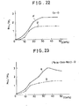
- Fig.23 and Fig.24 show respective perpendicular-incidence magnetic properties A, A' of various perpendicular-incidence magnetic films of Fe-Co-Ni-O prepared by using a 10% Co - 10% Ni - remainder Fe alloy (Fe 0.8 -Co 0.1 -Ni 0.1 ) as the target b while the 0 content is varied from 0 to 50 at%, by the sputtering process.
- B,B' are the respective perpendicular magnetic properties of various perpendicular-incidence magnetic films of the same composition prepared, for comparison, by the foregoing proposed evaporation process of this invention. In this case also, it is clear from those curves that the perpendicular magnetic properties of the products prepared by the sputtering process of this invention are better than those of the products prepared by the evaporation process of this invention.
- Fig.25 shows curves of the magnetic properties of perpendicular-incidence magnetic films of a Co 0.7 -o 0.3 composition prepared respectively by applying the respective acceleration voltages of the ⁇ d.c. voltage and the a.c. voltage during deposition of the sputtered Co atoms on the substrate while 0 2 gas is introduced.
- the oxygen introduction rate, the sputtering process, and the running speed of the substrate are controlled appropriately.
- the usual film thickness prepared by the sputtering process of this invention is in the range of 1000 - 10000 A°.
- the soft magnetic material film of permalloy or the like Before the substrate is subjected to the sputtering process, it may have applied to it the soft magnetic material film of permalloy or the like.
- a perpendicular-incidence magnetic film on a substrate is so prepared that vapors of ferro-magnetic metal Me are deposited on the substrate at a substantially perpendicular incident angle to the same while oxygen gas is introduced into the chamber.
- a perpendicular-incidence magnetic film of Me-O composition having improved magnetic properties can be obtained uniformly in a continuous manufacturing operation for a long period of time.
- the substrate is not heated, no curling or warping of the substrate occurs.
- the vapors of the ferro-magnetic metal may be ionized and/or additionally accelerated in speed by the application of electric voltage.
Abstract
Description
- This invention relates to a magnetic recording member and a manufacturing method for such a member.
- A recent development known to the applicants is that of a new magnetic recording system capable of high density recording, involving a perpendicular magnetic recording system and a magneto-optical recording system. A magnetic film proposed for such recording systems is a so-called perpendicular-incident deposition magnetic film, which has a magnetic anisotropy in the direction perpendicular to the plane of the film and meets the required conditions of "Ku ┴ ≧ 2π Ms2, Hc┴ > Hc//and Br┴ > Br//.
- As hitherto known, Co has a large magnets or magnetic crystalline anisotropy in the c axial direction of an hcp structure thereof, and for obtaining a perpendicular-incident deposition magnetic film by making use of this magnetic anisotropy, it is necessary or desirable to meet such requirements that (1) the direction of the c axis thereof is substantially perpendicular to the plane of the film, and (2) that the magnetic crystalline anisotropy Ku is larger than a diamagnetic field 2π Ms2 generated in the perpendicular direction to the plane of the film. However, the Co film has a large value of saturation magnetization Ms, and therefore does not meet the foregoing requirement (2), so that a perpendicular-incident deposition magnetic film cannot be made of Co.
- There has been also proposed, as a perpendicular-incident deposition magnetic film, a Co - Cr system thin film, and this film has been made by an evaporation process. However, the evaporation process is defective in that the vapor pressures of Co and Cr are substantially different from each other, and consequently it becomes difficult to keep a uniform Cr - Co composition ratio for a long period of time during manufacture of the magnetic film. A uniform magnetic film having a perpendicular magnetic property can be obtained only when evaporation deposition thereof on a substrate is carried out under the condition that the substrate is heated to 200 - 300°C. In other words, the perpendicular-incident deposition magnetic film cannot be obtained unless the substrate is heated, and curling of a tape-shaped substrate and warping of a substrate of the floppy disk type are caused by such heat. For preventing this, a heat resisting substrate has to be used, resulting in increased production costs.
- According to a first aspect of the invention there is provided a magnetic recording member characterized in that it comprises a substrate having formed on a surface thereof, either directly on the surface or on the intermediary of a soft magnetic material coating layer, a substantially perpendicular-incidence magnetic film comprising a composition of a magnetic metal and oxygen (Me-O), where the magnetic metal Me comprises one or more ferro-magnetic metals and/or magnetic alloys thereof.
- In one embodiment, the composition of magnetic metal Me-O is represented by (FexCoyNiz)1-mOm, where, substantially, 0 ≦ x ≦ 0.05, 0 ≦ z ≦ 0.40, x + y + z = 1, and 0.15 ≦ m ≦ 0.50.
- In another embodiment, the composition of magnetic metal Me-0 is represented by (FexCoyNiz)1-mOm, where, substantially, 0.40 ≦ x ≦ 1.0, 0 ≦ z ≦ 0.25,, x + y + z = 1, and 0.15 ≦ m ≦ 0.50.
- According to a second aspect of the invention there is provided a method of manufacturing a magnetic recording member characterized in that while oxygen gas is introduced into a vacuum treatment chamber a magnetic metal Me is vaporized and vapors thereof are deposited on a surface of a substrate at substantially perpendicular incidence to the surface thereof, while part of the metal is oxidized, so that there is formed on the surface of the substrate a substantially perpendicular-incidence magnetic film provided by a composition of (FexCoyNiz)1-mCm where, substantially, 0 ≦ x ≦ 0.05, 0 ≦ z " 0.40, x + y + z = 1, and 0.15 ≦ m ≦ 0.50.
- According to a third aspect of the invention there is provided a method of manufacturing a magnetic recording member characterized 'in that while oxygen gas is introduced into a vacuum treatment chamber a magnetic metal Me is vaporized and vapors thereof are deposited on a surface of a substrate at substantially perpendicular incidence to the surface thereof, while part of the metal is oxidized, so that there is formed on the surface of the substrate a substantially perpendicular-incidence magnetic film provided by a composition of (FexCoyNiz)1-mOm where, substantially, 0.40 ≦ x ≦ 1.0, 0≦ z ≦ 0.25, x + y + z = 1, and 0. 25 ≦ m ≦ 0.50.
- According to a fourth aspect of the invention there is provided a method of manufacturing a magnetic recording member characterized in that a magnetic metal Me provided in a vacuum treatment chamber is evaporated while 02 gas is introduced into the chamber so that part of vapors of the magnetic metal Me may be oxidized, and the partially oxidized vapors thereof are deposited on a substrate at a substantially perpendicular incident angle to a surface of the substrate and in the course of the perpendicular incident deposition of the magnetic metal vapors, part of the vapors is ionized, and thus there is formed on the surface of the substrate a substantially perpendicular-incidence magnetic film comprising a predetermined composition of Me and 0 atoms.
- In a development of the fourth aspect, in the course of substantially perpendicular incident deposition of the magnetic metal vapors, part thereof is ionized and the perpendicular incident deposition thereof on the substrate is carried out while the ionized vapors thereof are accelerated in speed by an electromagnetic field of d.c. or a.c. power.
- According to a fifth aspect of the invention there is provided a manufacturing method characterized in that a target comprising a magnetic metal Me provided in a vacuum treatment chamber is sputtered under the condition that 02 gas is introduced into the chamber and sputtered fine particles of the magnetic metal are deposited on a surface of a substrate at substantially perpendicular incidence thereon while part of the atoms of the sputtered fine particles is oxidized, so that there is formed on the surface of the substrate a substantially perpendicular-incidence magnetic film having a predetermined composition of magnetic metal Me and 0 atoms. -
- In a development of the fifth aspect there are provided in the vacuum treatment chamber the target of the magnetic metal Me and an electrode comprising the substrate itself, or an electrode provided near the substrate, and the electrode is supplied with an electric voltage of d.c. or a.c. power, and the target is sputtered while 02 gas is introduced into the chamber so that innumerable sputtered magnetic metal particles are deposited on the substrate at substantially perpendicular incidence thereon, while some atoms thereof are oxidized and thus there is formed on the substrate a substantially perpendicular-incidence magnetic film comprising a predetermined composition of magnetic metal and 0 atoms.
- In any of the above methods, the substrate may be provided with a soft magnetic material coating layer on which is formed the substantially perpendicular-incidence magnetic film.
- Preferred examples of the invention may provide a perpendicular-type recording member free from the foregoing inconveniences and may be characterized in that there is formed either directly on the surface of a substrate, or with the intermediary of a soft magnetic material coating layer on the surface of the substrate, a substantially perpendicular-incident deposition magnetic film. The film comprises a composition of magnetic metal Me and oxygen, where the magnetic metal Me represents any one type or more selected from the magnetic metals and the magnetic alloys. Thus the magnetic metal Me may include typically, but not restrictively, Fe, Co, Ni or a mixture thereof, and/or any alloy thereof. The soft magnetic material coating layer may be made of permalloy or an amorphous film made of Fe, Co, Co-Zr or the like.
- Preferred examples of the invention may provide a manufacturing method of the above perpendicular-type magnetic recording member and may be characterized in that while oxygen gas is introduced into a vacuum treatment chamber, a magnetic metal Me is vaporized and atomic vapors thereof are deposited on a surface of a substrate at a substantially perpendicular incident angle to the surface of the substrate. Part of the metal vapors may be oxidized, so that there is formed on the surface of the substrate a substantially perpendicular-incident deposition magnetic film provided by either a composition of (FexCoyNiz)1-mOm where, substantially, 0 ≦ x ≦ 0.05, 0 ≦ z ≦ 0.40, x + y + z = 1 and 0.15 ≦ m 0.50, or a composition of (FexCoyNiz)1-mOm where, substantially, 0.40 ≦ x ≦ 1.0, 0 ≦ z ≦ 0.25, x + y + z = 1 and 0.25 ≦ m ≦ 0.50.
- For a better understanding of the invention and to show how it may be put into effect, reference will now be made by way of example to the accompanying drawings in which:
- Fig.l is a side view of an apparatus for manufacturing a perpendicular-type magnetic recording member according to the invention;
- Figs.2A, 2B and 2C are diagrams showing the relationships between various Co-O compositions and the magnetic properties thereof;
- Fig.3 is a diagram showing characteristic curves of an hysteresis loop of one example of perpendicular-incidence magnetic films of the invention;
- Figs. 4 to 6 are diagrams showing the relationships between various Co-Ni-o compositions and magnetic properties thereof;
- Fig.7 is a diagram showing characteristic curves of an hysteresis loop of another example of an inventive magnetic film;
- Fig.8 is a diagram showing the composition ratios of three metallic components applicable to perpendicular-incidence magnetic films of the invention;
- Figs. 9 to 14 are diagrams showing the relationships between various composition ratios of three metallic components containing various contents of 0 atoms;
- Fig.15 is a side view of another apparatus for manufacturing magnetic recording members according to additional manufacturing methods of the invention;
- Figs.16 to 19 are diagrams showing the relationships between manufacturing methods of the invention and magnetic properties of magnetic films manufactured thereby;
- Fig.20 is a side view of another apparatus for manufacturing magnetic recording members by additional manufacturing methods of the invention; and
- Figs.21 to 25 are diagrams showing the relationships between manufacturing methods of the invention and magnetic properties of magnetic films manufactured thereby.
- In the first place, there are explained hereafter a perpendicular-type magnetic recording member having a perpendicular-incident deposition magnetic film comprising a composition of Co and 15 - 50 at% 0, and a manufacturing method thereof.
- Figure 1 shows a vacuum evaporation treatment apparatus for manufacturing the foregoing magnetic recording member according to the present invention. Numeral 1 denotes a vacuum treatment chamber, and there are provided in the chamber 1 a rotary cooling can 2 of cylindrical drum type and an electron
beam evaporation source 3 comprising a crucible positioned just under thecan 2. Thechamber 1 is connected through a control valve to a vacuum pump which is not shown. On opposite 'sides of an upper region above the rotary can 2 anunwinding roller 4 and a windingroller 5 are disposed and are arranged to be rotated by a motor (not shown). A tape-shaped substrate a made of such non-magnetic material as a PET material is mounted on theunwinding roller 4 and is arranged to be unrolled and run at a constant speed around a circumferential surface of the water-cooled can 2, and finally to be taken-up by thewinding roller 5. There is provided asupply pipe 6 for introducing oxygen into thechamber 1. A control valve may be interposed in thepipe 6 in the illustrated example, and thesupply pipe 6 is made so long that its open end is located near a surface of the running tape substrate a. Numeral 7 denotes right and left vapor-adhesion shield plates which are so disposed as to leave aspace interval 8 therebetween at a region through which the lowermost surface of thecan 2 faces theevaporation source 3, so that Co atoms evaporated from theevaporation source 3 may pass through thespace interval 8 and be deposited on the surface of the tape substrate a substantially perpendicular to the surface of the substrate a. Theplate 7 may be arranged to be movable to the right or left if desired. Numeral 9 denotes an electron beam heating means. - A magnetic recording member according to this invention is manufactured by using the above apparatus as follows:
- In the first place, after the interior of the
chamber 1 is evacuated to become below 1 x 10 Torr, a raw ferro-magnetic metal material b to be evaporated, Co metal for instance, is evaporated at a constant rate from theevaporation source 3 by electron beam heating. In the meantime, 02 gas is introduced into thechamber 1 through thesupply pipe 6 for oxidizing part of the Co vapors, and the partially oxidized Co vapors pass through thespace 8 and are deposited on the substrate a running on the lower surface of the cooledcan 2. The vapors are deposited substantially perpendicular or at normal incidence upon and to the substrate a, so that there is formed on the surface of the tape substrate a a perpendicular-incident deposition magnetic film comprising a composition of Co-O. - In this operation, by varying the introduced amount of 02 gas gor obtaining various partial pressures thereof in the chamber, there may be manufactured a large number of perpendicular-type magnetic recording members having respective Co-O perpendicular-incidence magnetic films comprising various composition ratios of Co-O. These members also have magnetic films which vary in thickness in the range of 1000 A° - 10000 A° , caused by varying the running speed of the tape substrate a. On those films of various Co-O composition ratios, magnetic properties are measured to obtain the relationships between the Co-0 composition ratios and the magnetic properties, as shown in Figures 2A, 2B, 2C. As will be understood therefrom, as the 0 content is increased, both a coercive force Hc┴ in the direction perpendicular to the film surface, and a residual magnetic flux density Br┴ thereof, are increased, and if the 0 content becomes above 15 atom.%, both Hc┴ and Br┴ become higher than a coercive force Hc// and a residual magnetic flux density Br// respectively, so that perpendicular deposition magnetic films can be obtained. However, if the O content is beyond 50 at%, a saturation magnetization value becomes zero, resulting in losing the magnetic properties of the film.
- Fig.3 shows characteristic curves of an hysteresis loop resulting from a perpendicular-incidence magnetic film comprising a typical composition of Co-36 at.% 0 , and from this Figure it is understood that this is a sufficient perpendicular-incident magnetic film. In the above manufacturing operation, films having any predetermined compositions in the range of Co-15-50 at% 0, can be also manufactured by varying the evaporation rate of Co while the introduction rate of 02 gas is varied. The relationships between the two are generally proportional to the incident deposition frequencies of both the atoms upon the substrate, and therefore if the Co evaporation rate is increased, it is necessary to increase the partial pressure of 02. As is clear from Figure 2C, the perpendicular-incident magnetic films comprising the Co-15-50 at% 0 compositions have excellent coercive force Hc┴ in the range of about 400 - 1000 θe, which are the best values for a perpendicular-incident magnetic film.
- When a previously proposed magnetic recording member having a perpendicular-incident deposition magnetic film comprising a Co-Cr composition is manufactured by the evaporation process, it is essential to deposit the Co and Cr atoms on a substrate which has been heated to 200 - 300 C . According to the present methods, heating of the substrate is not required at all.
- A good perpendicular-type magnetic film can be obtained even in a case where the substrate is cooled, or unheated to remain at a normal temperature. The present methods are not therefore limited to substrates which are made of an expensive heat-resisting plastics film such as polyimide or the like. In other words, the present material of the substrate to be used is not limited, so that an inexpensive material having no heat-resistance such as a PET film or the like can be also used, and a good perpendicular-type magnetic film can be obtained without heating the substrate. However, it is of course possible for the substrate to be heated if so desired.
- Also, when an already-proposed Co-Cr perpendicular type recording member is manufactured by the evaporation process, controlling of the Cr composition ratio is difficult, so that providing a uniform perpendicular magnetic film for a long time in a continuous manufacturing operation is difficult or impossible, and also violent curling or warping of the substrate is brought about by the heat. According to the present methods on the other hand, it is sufficient to keep constant the evaporation rate of the Co and the introduction rate of the 02 gas. It is thereby easy to form on the substrate a uniform perpendicular-incidence magnetic film in a continuous manufacturing operation, and curling and warping of the substrate hardly occurs when the substrate is not heated. This is very useful when manufacturing a floppy disk or magnetic tape or the like.
- The reason why the inventive Co-O magnetic film has the foregoing good magnetic properties is not wholly clear, but can be demonstrated as follows:
- When the Co atoms are deposited on the substrate at a substantially perpendicular-incident angle thereto, there is formed a coating film having a columnar structure in which the c axis of the hcp structure is oriented in the direction perpendicular to the plane of the film. During this evaporation, part of the evaporated Co atoms is oxidized by the introduced 02r and the resultant CoO oxide or similar oxide is deposited on the substrate, so that there is formed such a film structure that the fine particles of Co are coated with these non-magnetic oxides. Thus, the Co columnar particle has not only the crystal anisotropy but also a shape anisotropy, and thereby the perpendicular magnetic anisotropy of the film is improved. With such a film structure which is partially oxidized as above, an average saturation magnetization value is so lowered as to meet the requirement of Ku┴ ≧ 2π Ms2 to obtain the required perpendicular magnetic film. The diameter of the columnar Co particle is considered to be about from several hundreds A° to several thousands A°, and is a fine metal particle and accordingly has a high magnetic holding or coercive force.
- A minor amount of one or more other elements may be mixed in the foregoing Co-O perpendicular-incidence magnetic film. Also, any element which makes a solid solution with Co and does not cause harm to the h c p structure, for instance, Cr, V, Mo, W, Rh, Ti, Re etc. may be mixed therein in a minor amount.
- In addition, it has been found that one can use in the perpendicular magnetic recording system a magnetic recording member having, between the perpendicular-incidence magnetic film and the non-magnetic substrate, an intermediate magnetic film formed of permalloy or an amorphous film of Fe, Co, Co-Zr that has a comparatively soft magnetic property and is large in saturation magnetization. If such an intermediate film is used, the electric current required for recording can be decreased, and also the reproduction output can be increased. Such a perpendicular magnetic recording member may be manufactured in such a manner that initially the intermediate magnetic film is formed on a surface of the non-magnetic substrate, and then a perpendicular-incident deposition magnetic film comprising a predetermined Co-O composition is formed on a surface of the intermediate magnetic film according to the present manufacturing methods according to the present invention.
- Furthermore, when the present invention is applied to the manufacture of a floppy disc, the intermediate magnetic film as above may be formed on one or both surfaces of the substrate and then the perpendicular magnetic film comprising a predetermined Co-O composition formed on one or both surfaces of the intermediate magnetic film.
- Next, another example of the invention will be explained with reference to Figures 4 to 7, which concern a perpendicular-type magnetic recording member having a perpendicular-incident deposition magnetic film comprising a predetermined Co-Ni-O composition, and a manufacturing method thereof. Namely, the Co-Ni-O composition is (Co1-zNiz)1-mOm wherein 0 < z < 0.40 and 0.15 < m < 0.50.
- A perpendicular-type magnetic recording member having a perpendicular-incidence magnetic film comprising - the foregoing Co-Ni-O composition may be manufactured using the apparatus shown in Fig.l, and almost in the same manner as the first embodiment of this invention. Namely, initially, after the interior of the
chamber 1 is evacuated to be below 1 x 10" Torr, a Co-Ni alloy or a mixture of Co and Ni metals mixed in a predetermined ratio is evaporated at a constant rate by an electric beam heating means while 02 gas is introduced into thechamber 1 through thepipe 6. Partially oxidized vapors of Co and Ni are deposited on a surface of the substrate a running at a constant speed, substantially perpendicularly or normally thereto so that there is formed thereon a perpendicular-incident deposition magnetic film comprising a predetermined Co-Ni-O composition. - In this manufacturing method, perpendicular-type magnetic recording members having evaporation deposition magnetic films comprising various Co-Ni-O compositions are prepared by varying the 02 gas introduction rate for obtaining various 02 partial pressures in the
chamber 1, or by varying the mixing ratio of Co to Ni to be evaporated. - Also, by varying the running speed of the tape substrate a and/or varying the evaporation rate of Ni-Co there may be manufactured magnetic recording members having magnetic films which vary in thickness within the range 1000 A° - 10000 A° . Thus, relationships between the various magnetic films which differ in their composition ratio of Co-Ni-O, and their magnetic properties, have been examined. The results thereof are obtained as shown respectively in Figure 4, Figure 5 and Figure 6. As is clear from Fig.2, as the 0 component is increased, Hc┴ /Hc// representing a ratio of Hc┴ to Hc// is increased, and more than 15 atom % of O component makes the Hc┴ /Hc// ratio more than 1. As regards residual magnetic flux density Br┴ /Br// , as shown in Fig.5, as the 0 component is increased the residual magnetic flux density is increased also, and more than 15 atom % of the 0 component makes the residual magnetic flux density more than 1. However, as shown in Fig.6, saturation magnetization becomes zero when the O component is above 50 atom %. From the above results, within the area surrounded by the oblique lines in those Figures, that is, in the composition range of (Co1-zNiz)1-mOm where O < z < 0.40, 0.15 < m < 0.50, there can be obtained excellent perpendicular magnetic films according to the present invention.
- Figure 7 shows characteristic curves of an hysteresis loop of a typical perpendicular magnetic film comprising (Co0.9Ni0.1)0.7o0.3 according to the invention, and it is clear therefrom that the film is a sufficient perpendicular magnetic film. Thus, when the O component has to be in the range of 15 - 50 at%, and the Ni component ratio of Co and Ni is 60 < Co < 1 to 0 < Ni < 40 at% perpendicular magnetic films can be obtained. Beyond 40 at% of Ni content, the crystalline structure of the deposited metal grains becomes a f c c structure, and is much decreased in magnetic crystalline anisotropy, resulting in producing no perpendicular-incidence magnetic film.
- In addition, this inventive perpendicular-incidence magnetic film including the Ni material is improved in corrosion resistance. The perpendicular magnetic holding or coercive force of this inventive magnetic film is about 400 - 1000 θ e, which are the best values for a perpendicular-type magnetic recording member.
- In manufacturing the above magnetic film within the above Co-Ni-O composition range, it is general that if the Co-Ni evaporation rate is changed, the 02 gas introduction rate is also changed.
- Since the perpendicular incident deposition - frequencies of the Co atoms and the Ni atoms and those of the 0 atoms on the substrate are almost proportional one to another, if the Co-Ni evaporation rate is increased, it is necessary to increase the partial pressure of 02 by increasing the introduction rate of the 02 gas.
- In this example of the inventive method, the substrate is cooled by the
can 2, but it is not always necessary to cool the substrate. Good results also can be obtained when the substrate is not heated. When the substrate is not heated, no curling or warping thereof is brought about, resulting in a good product. - Thus, in this example also, inexpensive material can be used as the substrate.
- Also according to this example of the invention, the vapor pressure of Co and that of Ni.are almost equal, and therefore even if the Co-Ni alloy of any predetermined component ratio thereof is evaporated from a single
common evaporation source 3, a desired predetermined composition of Co-Ni evaporation deposition can be obtained on the substrate. Consequently, in this case, if the 02 introduction rate is kept constant, a predetermined uniform Co-Ni-O composition magnetic film can be produced over a long period of time in a continuous manufacturing operation. - In this example also, the aforementioned intermediate magnetic film, as mentioned in the first example, may be interposed between the substrate and the perpendicular-incidence magnetic film of Co-Ni-O composition.
- Next, a third example of this invention will be explained with reference to Figures 8 to 14 as follows:
- Namely, the third example relates to a perpendicular-type magnetic recording member having a perpendicular-incident magnetic film comprising an Fe-Co-Ni-O composition.
- In more detail, the Fe-Co-Ni-O composition is - (FexCoyNiz)1-mOm where O ≦ x ≦ 0.05, O ≦z ≦ 0.40, x + y + z = 1, 0.15 ≦ m ≦ 0.50 which is the region forming a h c p structure, or (FexCoyNiz)1-mOm where 0.40 ≦ x ≦ 1.0, 0 ≦ z ≦ 0.25, x + y + z = 1, 0.25 ≦ m ≦ 0.50 which is the region forming a b c c structure.
- A manufacturing method for the above magnetic recording member may be carried out by using the
aforementioned apparatus 1 in almost the same manner as in the previous two examples. - The perpendicular-incident deposition magnetic film thus obtained comprises a phase of perpendicularly grown columnar ferro-magnetic grains of Fe-Co-Ni and a phase of non-magnetic oxides thereof surrounding the columnar grains.
- There may be manufactured many magnetic recording members having the Fe-Co-Ni-O composition system in which the composition ratios of the four elements are varied, and magnetic properties are measured on those members. As a result thereof it has been found that, as shown in Fig.8, by partially oxidizing the composition ratios of Fe-Co-Ni falling in two regions A and B surrounded respectively by the oblique lines, there can be obtained excellent perpendicular-incidence magnetic films. The A region is one forming a b c c structure, and the B region is one forming h c p structure. As mentioned above it is necessary or desirable, for making a perpendicular-incidence magnetic film, that the perpendicular magnetic anisotropic energy Ku is larger than the diamagnetic field energy 2π Ms2 in the direction perpendicular to the phase of the film. In this case, as the perpendicular magnetic anisotropy a crystal magnetic anisotropy and a shape magnetic anisotropy can be considered. It has been found that the perpendicular magnetic film of this example has such a structure that the ferro-magnetic column grain phase of Fe-Co-Ni grown perpendicularly is surrounded by a non-magnetic phase of oxides of Fe-Co-Ni, and also the column grain is such a long one that the diameter of its short axis is about 200 - 1000 A° and that of its long axis is about 1000 A - 1 µm, so that this example of magnetic film has also a large shape magnetic anisotropy. In addition, as a result of X-ray diffraction it has been found that in the B region the c axis of the h c p structure is oriented in the perpendicular direction and also in the A region, the (100) direction of the b c c structure is oriented in the perpendicular direction, and both the axial directions are in the easy crystal magnetization directions, so that this embodiment of magnetic film has magnetic crystalline anisotropy.
- Thus, the role of the oxygen introduction is to separate the perpendicular columnar grains from each other by the non-magnetic oxides and to decrease the saturation magnetization of the entire magnetic film for satisfying the condition of K┴ ≧ 2π Ms2.
- As the oxygen gas introduction rate is increased while the evaporating rate of Fe, Co, Ni is kept constant, the concentration of oxygen in the film is increased and at the same time the decreasing in size of the columnar grain and the separation thereof from the oxide are developed, so that the decrease in the saturation magnetization and the anisotropic field in the perpendicular direction are increased. As a result of many experiments, it has been found that the perpendicular magnetic film is obtained when the oxygen component is more than 25 at% in the A region and more than 15 at% in the B region, and effective perpendicular magnetic films can be obtained in the range of 15 to 50 at% in oxygen content in the A region and, above all, the most effective one in the range of 35 - 45 at% O. In the B region effective films can be obtained in the range of 15 - 50 at% in 02 content and the most effective one in the range of 25 - 45 at% O. Namely, if the 0 content is beyond 50 at%, it causes the saturation magnetization to become zero. This is considered to be caused due to the fact that the oxides are FeO, CoO, NiO or the mixed crystallines thereof in the automatic ratio of 1 : 1.
- The Hc┴ of the perpendicular magnetic films obtained by the foregoing two A,B regions added therein with the oxygen contents of the foregoing predetermined range, are about 400 - 1000 θe, which are the best values for a perpendicular magnetic recording member. Those values are obtained by using the foregoing apparatus as shown in Fig.l and in almost the same manner as in the foregoing example cases, namely, even in a case where the substrate is not heated at a normal temperature, or in the case where it is cooled. The reason why good perpendicular magnetic properties can be obtained even under the condition that the substrate is not heated is considered to be due to such a fact that the 0 atoms easily diffuse or. spread over the film snrface.
- The previously proposed Co-Cr system perpendicular magnetic film is obtained with such a structure that Cr atoms are segregated around the crystal boundaries of the Co columnar grains to form non-magnetic phases separating the columnar grains from each other. For forming this structure, it is necessary to diffuse Cr atoms over the film surface, and this is achieved by raising the temperature of the substrate. This effect cannot be achieved when the substrate is not heated or when the temperature of the heating is low. According to this invention however, oxygen gas is arranged to be introduced and easily diffuses over the film surface. Even in a case when the substrate is not heated, a good perpendicular-incidence magnetic film can be obtained. A manufacturing method for the above products is almost the same as the previous two examples.
- Further, advantages brought about by the manufacturing method are substantially the same as those in the two previous examples. Namely, there can be obtained a uniform magnetic film for a long period of time in a continuous manufacturing operation, and no curling or warping of the product is produced.
- By using the foregoing apparatus shown in Fig.1 almost in the same manner as already described in the two previous examples, there may be produced various perpendicular-type magnetic films of thicknesses which vary in the range of 1000 A° - 10000 A° , and for those various products magnetic properties and alloy compositions thereof are measured.
- Figures. 9 and 10 show the resultant values of Hc┴ /Hc// and Br┴ /Br// in the case where the 02 component is kept constant at 15 at% while the Fe-Co-Ni composition is varied in ratio thereof. As clear therefrom, in the B region Hc┴ /Hc// and Br┴ /Br// are both more than 1. In A Hc┴ /Hc// is more than 1, but Br┴ /Br// is less than 1. Thus, it has been concluded that the A and B regions indicate that there cannot be produced predetermined perpendicular-incidence magnetic film when the 02 content is 15 at%. It has been also found that in the f c c phase region outside the A and B regions, Hc┴ /Hc// and Br┴ /Br// are both less than 1, so that no perpendicular-incidence magnetic films can be produced in the f c c phase structure. Similarly, Figs. 11 and 12 show a case including a constant content of 25 at% 0, and indicate that there are produced perpendicular-incidence magnetic films in the A and B regions. Figs.13 and 14 show a case including a constant content of 40 at% 0 and indicate that there are produced perpendicular-incidence magnetic films in the A and B regions.
- In the third example also, there may be manufactured perpendicular magnetic recording members having the foregoing intermediate soft magnetic film interposed betweeen the substrate and the perpendicular-incidence ferromagnetic film.
- Furthermore, this embodiment of the foregoing manufacturing method may provide a manufacturing method for manufacturing a further improved perpendicular-type magnetic recording member, characterized in that a magnetic metal Me in a vacuum treatment chamber is vaporized while 02 gas is introduced into the chamber for oxidizing part of vapors of the magnetic metal Me, and the vapors thereof are deposited on a substrate at a substantially perpendicular incident onto a surface of the substrate and, in the course of the perpendicular-incident deposition of the vapors of the magnetic metal, part of the vapors is ionized, and thus there is formed thereon a perpendicular-deposition magnetic film comprising a predetermined composition of Me and 0 atoms.
- Thus, according to this method, the crystallization of ferro-magnetic columnar grains is improved and the magnetic crystalline anisotropy is increased. In addition, lattice defects in the columnar grains or subgrains can be eliminated and orderly oriented columnar grains can be obtained, so that shape magnetic anisotropy thereof is improved.
- According to another aspect,the ionized vapors may be accelerated in speed by an electromagnetic field of d.c. or a.c. power. Examples will be explained with reference to Figs. 15 to 19. Fig. 15 shows an apparatus for carrying out the above manufacturing methods. The apparatus is different from the apparatus shown in Fig.l, in being-provided with the following arrangement.
- Referring to Fig.15, the
apparatus 1 is provided with an ionizing means. Namely, the ionizing means comprises anelectrode 10 provided in a space located above theevaporation source 3, and a d.c. power source or anRF source 11 is connected to theelectrode 10. Theelectrode 10 comprises an anode which is arranged to be supplied with a positive d.c. current or an RF voltage for ionizing part of the metal vapors and oxygen at a high efficiency. In addition, the apparatus is provided with an acceleration means comprising a mesh-shapedelectrode 8 for acceleration, which is located near the substrate portion running on the lower end surface of thecan 2, with a d.c. or a.c.source 13 being connected thereto. - By using this apparatus, a perpendicular-type magnetic recording member is manufactured in the following way, for instance. Namely, the
chamber 1 is evacuated to become below 1 x 10⁻⁵ Torr, and a predetermined composition of Me b is heated to be evaporated by the electron heating means 9, while oxygen is introduced into thechamber 1 through theoxygen introduction pipe 6. For instance, the evaporating rate is 200 A°/sec. and the partial pressure of 02 gas is 1 x 10⁻⁴ Torr. Under those conditions, a positive d.c. voltage is applied to theanode 10 connected to the d.c.power source 11. Electrons from the electron beam and secondary electrons from the evaporating liquid surface of the Me are attracted to the positive electric field, and at that time the metal vapors and oxygen atoms collide with those electrons in the electric field space and are ionized. Namely, a comparatively greater part of the ionized metal vapors can be ionized because, while those electrons are being attracted to the positive electric field by the positive voltage applied to theanode 10, the metal vapors are brought into contact with such attracted electrons. In this way, in this case a greater part of the oxygen atoms also can be ionized. - The ionization of the metal vapors and oxygen atoms can be carried out by the application of the positive electrode voltage by using an RF electron voltage instead of the direct current. In the case of using the RF voltage, the RF source also serves as an electron generating source, so that it becomes unnecessary to use the electron beam means as the heating means 9, and a non-electron beam type heating means such as an ordinary electric heater or the like can be used in place of the electron beam type means.
- Thus, the vapors of the magnetic metal which have been partially ionized together with the oxygen gas pass through the
space 8 between theplates can 2, at generally perpendicular incidence on the surface of the substrate, so that there is formed a partially ionized and oxidized perpendicular-incidence magnetic film. - In the above manufacturing method, for example Co metal is used as the ferro-magnetic metal Me, and the evaporating speed and the 0 gas partial pressure are set to be 200 A0/sec. and 1 x 10⁻⁴ Torr respectively. The ionizing electric current for applying a positive voltage to the
anode 10 may be varied, so that there are manufactured perpendicular-type magnetic recording tape members having various perpendicular-incident magnetic films of the Co-0 system. On those products, the relationship between the change in the ionizing electric voltage and magnetic properties of the products are noted. In the meantime, for comparison, various perpendicular-type magnetic recording tape members having various perpendicular magnetic films of the Co-O system are manufactured by the same method as the above but with theanode 10 not supplied with d.c., and are examined as regards the magnetic properties thereof. The results thereof are shown in Fig.16. As clear therefrom, the values of Hc┴ /Hc// and Br1 /Br// are the lowest in the magnetic films manufactured without application of the positive electric voltage to theanode 10, and as the voltage applied thereto is increased, those values are increased. In this case, it has been found that those values become almost constant at an ionizing electric current of about 3 A or more. - According to an additional manufacturing method, the previously positively-charged metallic vapors are supplied with an acceleration negative voltage applied to the mesh-shaped
electrode 8 connected to the d.c.source 13 through aconnector 12, so that those vapors are accelerated in speed and consequently reaction between the accelerated metal atoms and oxygen atoms and the surface diffusion of the metallic atoms is increased, and there can be formed on the substrate a perpendicular magnetic film which is higher, in the foregoing magnetic properties Hc┴ /Hc// and Br┴ /Br//, than the foregoing perpendicular magnetic films formed without being supplied with the acceleration means. - Further, as the acceleration means, if a.c. power is used instead of d.c. power, so that.a positive electric voltage and a negative one may be applied alternately to the
electrode 8, at each time when the negative voltage is applied the ionized metallic vapors are accelerated thereby and in addition at each time when the positive voltage is applied, the negatively-charged 0 atoms are accelerated, so that a uniform reaction between the metallic vapors and the oxygen atoms and the diffusion thereof can be improved as compared with the application of d.c. power. - More specifically, for example, various perpendicular-type recording members having various perpendicular-incidence magnetic films of the Co-O system are manufactured by the ionizing electric current being set constant at 2.0 A, and the acceleration voltage applied to the
acceleration electrode 8 from the d.c. or a.c. power being varied. The relationship between the acceleration electric voltage and the magnetic properties of those films have been examined. The results thereof are shown in Fig.17. As is clear from Fig.16 and Fig. 17, the values of Hcl /Hc// and those of Brl /Br// associated with the a.c. and d.c. powers if the acceleration voltage is applied, is improved as compared with the case in which the acceleration voltage is not applied, and also as the acceleration electric voltage is increased, the respective properties are also increased. Further, if the substrate is made of an electrically insulating material such as polyethylene terephthalate (PET) or the like, the use of a.c. power is preferable. - Figs.18 and 19 show the results of examining the relationship of the ionizing current and the acceleration voltage with the magnetic properties of perpendicular-incidence magnetic films of Fe-Co-Ni-O composition manufactured by the foregoing manufacturing method using the apparatus shown in Fig.15 when an Fe-10% Co-10% Ni alloy is used as the evaporating material metal b. From those Figures 18 and 19, it is clear that similarly to the above example case of a Co-O composition film, the ionization and acceleration effects can be recognized.
- As a result of many experiments and examinations, it has been found that perpendicular-incidence magnetic films of Me1-mOm with improved properties brought about by the invention, can be obtained with such a metal and oxygen composition range as mentioned below :-(FexCoyNiz)1-mOm where O ≦ x ≦ 0.05, O ≦ z ≦ 0.40, x + y + z = 1, and 0.15 ≦ m ≦ 0.50 or (FexCoyNiz)1-mOm where 0.40 ≦ x ≦ 1.0, O ≦ z ≦ 0.25, x + y + z = 1, and 0.25 ≦ m ≦ 0.50.
- In the foregoing examples also, the perpendicular-incidence magnetic film may have the aforementioned soft magnetic material film between the substrate and the magnetic film.
- According to another manufacturing method according to the present invention, a perpendicular-type magnetic recording member having a perpendicular magnetic film comprising the Me-0 composition can be manufactured by a sputtering process, and it may be characterized in that a target comprising a magnetic metal Me in a vacuum treatment chamber is sputtered under the condition that 02 gas is introduced thereinto and the sputtered magnetic metal particles are deposited on a surface of a substrate at substantially perpendicular incident angle thereto, while part of the atoms of the innumerable sputtered particles of magnetic metal Me is oxidized, so that there is formed on the surface of the substrate a perpendicular-incidence magnetic film having a predetermined composition of magnetic metal Me and 0 atoms.
- Thus, there can be obtained a perpendicular-type magnetic recording member which has improved properties of Hc┴ /Hc// and Br┴ /Br//.
- In order to improve the magnetic properties produced by the above manufacturing method, an additional manufacturing method may be provided characterized in that there are provided in the vacuum treatment chamber the target of the magnetic metal Me and an electrode comprising the substrate itself or an electrode provided near the substrate and under the condition that the electrode is supplied with an electric (possibly negative) voltage which is either d:c. or a.c., and the target is sputtered while 02 gas is introduced into the chamber so that innumerable sputtered magnetic fine metal Me particles are deposited on the substrate at substantially perpendicular incident angle thereto, while some atoms thereof are oxidized, so that there is formed on the substrate a perpendicular magnetic film comprising a predetermined composition of magnetic metal Me and 0 atoms.
- Figs. 20 - 25 relate to examples of the foregoing methods according to this invention. Referring to Fig.20, the
apparatus 1 is suitable for carrying out those manufacturing methods of this invention. The apparatus is almost the same as that shown in Fig.l and Fig.15, but is different therefrom in that instead of evaporation means a sputtering means is provided therein. Namely, just under thecan 2, there is provided a sputteringcathode 14 on which a ferro-magnetic metal layer b is provided. Preferably, the mesh-shapedacceleration electrode 10 connected to the d.c. or a.c.power source 11 is located near the surface of the substrate a running on the lower end surface of thecan 3.Numeral 15 denotes an inlet pipe for introducing a sputtering gas such as Ar or the like into thechamber 1. - For carrying out an example of the invention, the apparatus of Fig.20 is operated as follows: The
chamber 1 is evacuated to become below 1 x 10⁻⁵ Torr, Ar gas is introduced into thechamber 1 through theinlet pipe 15, and the metal Me layer b is sputtered under Ar gas pressure of 5 x 10⁻³ Torr. The sputtering is carried out by a d.c. magnetron sputtering process. As a result, a comparatively large amount of the innumerable sputtered Me atoms, usually about 10% thereof, become ionized atoms. Energy generated at the time when the Me atoms are sputtered is as high as about 10 - 100 eV and can serve to produce a perpendicular-incidence magnetic film of the Me-O system which has improved perpendicular magnetic anisotropy. - On the other hand, 02 gas is introduced at a constant flow rate into the
chamber 1 from theoxygen supply pipe 6, and is brought into contact with the rising sputtered and partially-ionized metal Me atoms so that part of the metal atoms is oxidized. Mixed vapors of the metal atoms and the oxidized atoms are deposited on the substrate running at a predetermined constant speed, through theinterval opening 8, at a substantially perpendicular incident angle to the substrate. There is thus formed on the surface of the substrate a perpendicular-incidence magnetic film of a predetermined composition comprising two phases of the magnetic metal Me atoms and non-magnetic oxides thereof. Thus perpendicular-incidence magnetic recording film thus formed is taken up by theroller 5. - According to a development of this method, during the operation of the above manufacturing method, a negative voltage is applied to the
acceleration electrode 10 from the d.c.power source 11 for instance, so that there is created around the electrode 10 a negative electric field. As a result of this field the partially ionized sputtered positively-charged metal Me atoms are accelerated in speed by theelectrode 10 when they go upwards into that negative electric field. In a case where thepower source 11 is a.c., theelectrode 10 is given an alternate application of positive and negative voltages, and thereby there is caused the acceleration of ionized Me atoms and of partially ionized 0 atoms alternately. Consequently there can be carried out effectively near the mesh-shaped electrode 10 a reaction between the sputtered metal Me atoms and the oxygen atoms and a diffusion thereof, and accordingly there can be formed a good perpendicular-incidence magnetic film of the composition of metal and O atoms comprising two phases of metal Me atoms and oxides thereof which are uniformly diffused on the entire surface of the substrate a. If the material of the substrate is electrically insulating, use of the a.c. voltage application is preferable in order to prevent electrical charging. In a case where an electrically conductive substrate is used, the substrate itself can be arranged to be used as an acceleration electrode by being connected to the a.c. or d.c. power source (this version not being illustrated). - In Figs. 21 and 22, curves A and A' show the respective perpendicular magnetic properties Hc┴ /Hc// and Br┴ /Br// of various perpendicular-incidence magnetic films prepared according to this invention and by varying the composition ratio of oxygen to Co which is used as the target b. Also in those figures, curves B and B' show the respective magnetic properties of various perpendicular-incidence magnetic films of the same composition ratio of Co-O as above prepared, for comparison, by the foregoing proposed evaporation-process of this invention in which Co is evaporated by the electron beam heating means, while 02 is introduced into the chamber, and is deposited on the substrate at a substantially perpendicular incident angle to the same as explained as the first example. As is clear from those curves, the magnetic properties of the Co-O perpendicular-incidence magnetic films prepared by the sputtering process are better than those prepared by the evaporation process.
- Fig.23 and Fig.24 show respective perpendicular-incidence magnetic properties A, A' of various perpendicular-incidence magnetic films of Fe-Co-Ni-O prepared by using a 10% Co - 10% Ni - remainder Fe alloy (Fe0.8-Co0.1-Ni0.1) as the target b while the 0 content is varied from 0 to 50 at%, by the sputtering process. B,B' are the respective perpendicular magnetic properties of various perpendicular-incidence magnetic films of the same composition prepared, for comparison, by the foregoing proposed evaporation process of this invention. In this case also, it is clear from those curves that the perpendicular magnetic properties of the products prepared by the sputtering process of this invention are better than those of the products prepared by the evaporation process of this invention.
- Fig.25 shows curves of the magnetic properties of perpendicular-incidence magnetic films of a Co0.7-o0.3 composition prepared respectively by applying the respective acceleration voltages of the θ d.c. voltage and the a.c. voltage during deposition of the sputtered Co atoms on the substrate while 02 gas is introduced.
- As clear therefrom, the respective properties Hc┴ /Hc// and Br┴ /Br// can be improved by the application of the acceleration voltages, and the application of a.c. voltage provides a better improvement in those properties than that of d.c. voltage.
- The perpendicular-incidence magnetic films of the Me-O composition prepared by the sputtering process of this invention can be obtained with (FexCoyNiz)1-mOm where O≦x≦0.05, O ≦ z ≦ 0.40, x + y + z = 1, and 0.15 ≦ m ≦ 0.05, or with (FexCoyNiz)1-mOm where 0.40 ≦ x ≦ 1.0, O ≦ z≦0.25, x + y + z = 1 and 0.25 ≦ m ≦ 0.50. In order to obtain magnetic films with such compositions as are mentioned above, the oxygen introduction rate, the sputtering process, and the running speed of the substrate are controlled appropriately. In general, the usual film thickness prepared by the sputtering process of this invention is in the range of 1000 - 10000 A°. Before the substrate is subjected to the sputtering process, it may have applied to it the soft magnetic material film of permalloy or the like.
- Thus, according to examples of this invention, in manufacturing a perpendicular magnetic recording member, a perpendicular-incidence magnetic film on a substrate is so prepared that vapors of ferro-magnetic metal Me are deposited on the substrate at a substantially perpendicular incident angle to the same while oxygen gas is introduced into the chamber. In this way, a perpendicular-incidence magnetic film of Me-O composition having improved magnetic properties can be obtained uniformly in a continuous manufacturing operation for a long period of time. When the substrate is not heated, no curling or warping of the substrate occurs. In the course of manufacturing the inventive film, the vapors of the ferro-magnetic metal may be ionized and/or additionally accelerated in speed by the application of electric voltage. The magnetic properties such as Hc┴ /Hc// and Br┴ /Br// of the film can thus be more improved. Further, if the composition ratio of Me and oxygen atoms of the magnetic film of this invention comprises (FexCoyNiz)1-mOm where O ≦ x " 0.05, O ≦ z ≦ 0.40, x + y + z = 1 and or (FexCoyNiz)1-mOm where 0.15≦ m ≦ 0.50 or in the region where 0.40 ≦ x ≦ 1.0, 0 ≦ z ≦ 0.25, x + y + z = 1 and 0.25 ≦ m ≦ 0.50, there can be provided perpendicular-type magnetic recording members which are excellent as regards those magnetic properties.
Claims (10)
Applications Claiming Priority (10)
| Application Number | Priority Date | Filing Date | Title |
|---|---|---|---|
| JP36653/83 | 1983-03-08 | ||
| JP3665283A JPS59163810A (en) | 1983-03-08 | 1983-03-08 | Vertical magnetic recording means and manufacture of the same |
| JP58036653A JPS59162622A (en) | 1983-03-08 | 1983-03-08 | Vertical magnetic recording material and its production |
| JP36652/83 | 1983-03-08 | ||
| JP58072075A JPS59198707A (en) | 1983-04-26 | 1983-04-26 | Perpendicularly magnetic recording material and manufacture thereof |
| JP72075/83 | 1983-04-26 | ||
| JP8578683A JPS59213033A (en) | 1983-05-18 | 1983-05-18 | Manufacture of vertical magnetic recording body |
| JP85786/83 | 1983-05-18 | ||
| JP88389/83 | 1983-05-21 | ||
| JP8838983A JPS59215025A (en) | 1983-05-21 | 1983-05-21 | Manufacture of vertical magnetic recording body |
Publications (2)
| Publication Number | Publication Date |
|---|---|
| EP0122030A1 true EP0122030A1 (en) | 1984-10-17 |
| EP0122030B1 EP0122030B1 (en) | 1987-08-26 |
Family
ID=27521812
Family Applications (1)
| Application Number | Title | Priority Date | Filing Date |
|---|---|---|---|
| EP84301530A Expired EP0122030B1 (en) | 1983-03-08 | 1984-03-08 | A magnetic recording member and a manufacturing method for such a member |
Country Status (3)
| Country | Link |
|---|---|
| US (1) | US5024854A (en) |
| EP (1) | EP0122030B1 (en) |
| DE (1) | DE3465647D1 (en) |
Cited By (11)
| Publication number | Priority date | Publication date | Assignee | Title |
|---|---|---|---|---|
| EP0169929A1 (en) * | 1984-08-02 | 1986-02-05 | Konica Corporation | Magnetic recording medium |
| EP0169928A1 (en) * | 1984-08-02 | 1986-02-05 | Konica Corporation | Magnetic recording medium |
| NL8601273A (en) * | 1985-05-20 | 1986-12-16 | Res Dev Corp Of Japan Nakao Ak | MAGNETIZED ANISOTROPE THIN FILM. |
| EP0238047A2 (en) * | 1986-03-18 | 1987-09-23 | Kanegafuchi Kagaku Kogyo Kabushiki Kaisha | Magnetic storage medium with perpendicular anisotropy |
| DE3710477A1 (en) * | 1986-03-31 | 1987-10-08 | Japan Res Dev Corp | Thin layer with vertical anisotropy of magnetization |
| US4726988A (en) * | 1984-03-22 | 1988-02-23 | Toray Industries, Inc. | Vertical magnetic recording medium |
| EP0335259A2 (en) * | 1988-03-29 | 1989-10-04 | Kanegafuchi Kagaku Kogyo Kabushiki Kaisha | Perpendicular magnetic storage medium |
| US4873154A (en) * | 1987-02-04 | 1989-10-10 | Fuji Photo Film Co., Ltd. | Magnetic recording medium containing Fe, Co, N and O |
| EP0351815A2 (en) * | 1988-07-20 | 1990-01-24 | Kanegafuchi Kagaku Kogyo Kabushiki Kaisha | Perpendicular magnetic recording medium, method for its manufacturing and method for recording and reproducing |
| EP0586142A1 (en) * | 1992-08-26 | 1994-03-09 | Toda Kogyo Corp. | Medium for perpendicular magnetic recording and multi-layered film for this medium |
| EP0600697A1 (en) * | 1992-11-30 | 1994-06-08 | Toda Kogyo Corp. | Perpendicular magnetic film, multilayered film for perpendicular magnetic film and process for producing perpendicular magnetic film |
Families Citing this family (5)
| Publication number | Priority date | Publication date | Assignee | Title |
|---|---|---|---|---|
| US5287239A (en) * | 1989-07-05 | 1994-02-15 | Kabushiki Kaisha Toshiba | Magnetic head using high saturated magnetic flux density film and manufacturing method thereof |
| EP0443478A3 (en) * | 1990-02-19 | 1992-03-11 | Kanegafuchi Kagaku Kogyo Kabushiki Kaisha | Magnetic recording medium and method for preparing the same |
| JPH04356721A (en) * | 1991-03-28 | 1992-12-10 | Fuji Photo Film Co Ltd | Magnetic recording medium |
| US7625633B2 (en) * | 2003-03-25 | 2009-12-01 | Shin-Etsu Polymer., Ltd. | Electromagnetic noise suppressor, article with electromagnetic noise suppressing function, and their manufacturing methods |
| US7625640B2 (en) * | 2004-02-24 | 2009-12-01 | Shin-Etsu Polymer Co., Ltd. | Electromagnetic noise suppressor, structure with electromagnetic noise suppressing function, and method of manufacturing the same |
Citations (4)
| Publication number | Priority date | Publication date | Assignee | Title |
|---|---|---|---|---|
| FR2376485A1 (en) * | 1976-12-29 | 1978-07-28 | Matsushita Electric Ind Co Ltd | METHOD AND DEVICE FOR MANUFACTURING MAGNETIC BANDS |
| US4239835A (en) * | 1976-07-15 | 1980-12-16 | Matsushita Electric Industrial Co., Ltd. | Magnetic recording medium |
| DE3021155A1 (en) * | 1980-06-02 | 1981-12-03 | Hans 1000 Berlin Wolff | Multilayer magnetic coatings for magnetic tape - where double coating process provides uniform magnetisation and eliminates drop=outs |
| DE3226639A1 (en) * | 1981-07-17 | 1983-02-03 | Fuji Photo Film Co., Ltd., Minami-Ashigara, Kanagawa | Magnetic recording medium |
Family Cites Families (8)
| Publication number | Priority date | Publication date | Assignee | Title |
|---|---|---|---|---|
| CA684673A (en) * | 1964-04-21 | E. Bleil Carl | Film formation by reaction of evaporated metal with oxygen | |
| JPS5891B2 (en) * | 1977-09-30 | 1983-01-05 | 俊一 岩崎 | magnetic recording medium |
| JPS54116202A (en) * | 1978-03-01 | 1979-09-10 | Tdk Corp | Production of magnetic recording media |
| US4198467A (en) * | 1978-09-28 | 1980-04-15 | Corning Glass Works | Glass articles with NiFe2 O4, CoFe2 O4, or (Co,Ni)Fe2 O4 surface layers |
| JPS5571006A (en) * | 1978-11-22 | 1980-05-28 | Matsushita Electric Ind Co Ltd | Magnetic thin film and its manufacturing method |
| JPS6033289B2 (en) * | 1979-07-18 | 1985-08-02 | 松下電器産業株式会社 | Metal thin film magnetic recording media |
| JPS57100627A (en) * | 1980-12-12 | 1982-06-22 | Teijin Ltd | Manufacture of vertical magnetic recording medium |
| JPS57152517A (en) * | 1981-03-17 | 1982-09-20 | Matsushita Electric Ind Co Ltd | Magnetic recording medium |
-
1984
- 1984-03-08 DE DE8484301530T patent/DE3465647D1/en not_active Expired
- 1984-03-08 EP EP84301530A patent/EP0122030B1/en not_active Expired
-
1989
- 1989-09-22 US US07/412,535 patent/US5024854A/en not_active Expired - Lifetime
Patent Citations (4)
| Publication number | Priority date | Publication date | Assignee | Title |
|---|---|---|---|---|
| US4239835A (en) * | 1976-07-15 | 1980-12-16 | Matsushita Electric Industrial Co., Ltd. | Magnetic recording medium |
| FR2376485A1 (en) * | 1976-12-29 | 1978-07-28 | Matsushita Electric Ind Co Ltd | METHOD AND DEVICE FOR MANUFACTURING MAGNETIC BANDS |
| DE3021155A1 (en) * | 1980-06-02 | 1981-12-03 | Hans 1000 Berlin Wolff | Multilayer magnetic coatings for magnetic tape - where double coating process provides uniform magnetisation and eliminates drop=outs |
| DE3226639A1 (en) * | 1981-07-17 | 1983-02-03 | Fuji Photo Film Co., Ltd., Minami-Ashigara, Kanagawa | Magnetic recording medium |
Cited By (21)
| Publication number | Priority date | Publication date | Assignee | Title |
|---|---|---|---|---|
| US4726988A (en) * | 1984-03-22 | 1988-02-23 | Toray Industries, Inc. | Vertical magnetic recording medium |
| EP0169928A1 (en) * | 1984-08-02 | 1986-02-05 | Konica Corporation | Magnetic recording medium |
| EP0169929A1 (en) * | 1984-08-02 | 1986-02-05 | Konica Corporation | Magnetic recording medium |
| NL8601273A (en) * | 1985-05-20 | 1986-12-16 | Res Dev Corp Of Japan Nakao Ak | MAGNETIZED ANISOTROPE THIN FILM. |
| US4797330A (en) * | 1986-03-18 | 1989-01-10 | Kanegafuchi Kagaku Kogyo Kabushiki Kaisha | Perpendicular magnetic storage medium |
| EP0238047A3 (en) * | 1986-03-18 | 1989-08-30 | Kanegafuchi Kagaku Kogyo Kabushiki Kaisha | Magnetic storage medium with perpendicular anisotropy |
| EP0238047A2 (en) * | 1986-03-18 | 1987-09-23 | Kanegafuchi Kagaku Kogyo Kabushiki Kaisha | Magnetic storage medium with perpendicular anisotropy |
| US5034286A (en) * | 1986-03-18 | 1991-07-23 | Kanegafuchi Kagaku Kogyo Kabushiki Kaisha | Perpendicular magnetic storage medium |
| DE3710477A1 (en) * | 1986-03-31 | 1987-10-08 | Japan Res Dev Corp | Thin layer with vertical anisotropy of magnetization |
| DE3710477C2 (en) * | 1986-03-31 | 1999-05-12 | Japan Res Dev Corp | Thin layer with perpendicular magnetization isotropy |
| US4873154A (en) * | 1987-02-04 | 1989-10-10 | Fuji Photo Film Co., Ltd. | Magnetic recording medium containing Fe, Co, N and O |
| US5045412A (en) * | 1988-03-29 | 1991-09-03 | Kanegafuchi Kagaku Kogyo Kabushiki Kaisha | Perpendicular magnetic storage medium |
| EP0335259A2 (en) * | 1988-03-29 | 1989-10-04 | Kanegafuchi Kagaku Kogyo Kabushiki Kaisha | Perpendicular magnetic storage medium |
| EP0335259A3 (en) * | 1988-03-29 | 1990-10-31 | Kanegafuchi Kagaku Kogyo Kabushiki Kaisha | Perpendicular magnetic storage medium |
| EP0351815A2 (en) * | 1988-07-20 | 1990-01-24 | Kanegafuchi Kagaku Kogyo Kabushiki Kaisha | Perpendicular magnetic recording medium, method for its manufacturing and method for recording and reproducing |
| EP0351815A3 (en) * | 1988-07-20 | 1990-12-27 | Kanegafuchi Kagaku Kogyo Kabushiki Kaisha | Perpendicular magnetic recording medium, method for its manufacturing and method for recording and reproducing |
| EP0586142A1 (en) * | 1992-08-26 | 1994-03-09 | Toda Kogyo Corp. | Medium for perpendicular magnetic recording and multi-layered film for this medium |
| US5580671A (en) * | 1992-08-26 | 1996-12-03 | Toda Kogyo Corporation | Perpendicular magnetic film and multi-layered film for perpendicular magnetic film |
| EP0600697A1 (en) * | 1992-11-30 | 1994-06-08 | Toda Kogyo Corp. | Perpendicular magnetic film, multilayered film for perpendicular magnetic film and process for producing perpendicular magnetic film |
| US5496631A (en) * | 1992-11-30 | 1996-03-05 | Toda Kogyo Corporation | Perpendicular magnetic film, multilayered film for perpendicular magnetic film and process for producing perpendicular magnetic film |
| US5628953A (en) * | 1992-11-30 | 1997-05-13 | Toda Kogyo Corporation | Process for producing perpendicular magnetic film |
Also Published As
| Publication number | Publication date |
|---|---|
| EP0122030B1 (en) | 1987-08-26 |
| US5024854A (en) | 1991-06-18 |
| DE3465647D1 (en) | 1987-10-01 |
Similar Documents
| Publication | Publication Date | Title |
|---|---|---|
| EP0093412B1 (en) | Magnetron sputtering apparatusand a method for forming a magnetic thinfilm on the surface of a substrate | |
| EP0122030A1 (en) | A magnetic recording member and a manufacturing method for such a member | |
| US4239835A (en) | Magnetic recording medium | |
| US3898952A (en) | Apparatus for production of magnetic recording medium | |
| US4382110A (en) | Magnetic recording medium | |
| US4767516A (en) | Method for making magnetic recording media | |
| EP0132398B1 (en) | A method and apparatus for ion beam generation | |
| US4003813A (en) | Method of making a magnetic oxide film with high coercive force | |
| US4399013A (en) | Method of producing a magnetic recording medium | |
| US4990361A (en) | Method for producing magnetic recording medium | |
| JPH061551B2 (en) | Method of manufacturing magnetic recording medium | |
| JPH031810B2 (en) | ||
| JPH0352136B2 (en) | ||
| EP0190854A2 (en) | Method for producing a perpendicular magnetic recording medium | |
| JPS6367328B2 (en) | ||
| US20040052935A1 (en) | Magnetic thin film and production method therefor | |
| JPH0320815B2 (en) | ||
| JPS5840248B2 (en) | Magnetic recording medium and its manufacturing method | |
| JPH0311531B2 (en) | ||
| JPS5837844A (en) | Production of magnetic recording medium | |
| JPS5840249B2 (en) | Magnetic recording medium and its manufacturing method | |
| JPH07192259A (en) | Production of magnetic recording medium | |
| JPH0371420A (en) | Perpendicular magnetic recording medium and its production | |
| JPS59148139A (en) | Manufacture of vertical magnetic recording medium | |
| JPH0341896B2 (en) |
Legal Events
| Date | Code | Title | Description |
|---|---|---|---|
| PUAI | Public reference made under article 153(3) epc to a published international application that has entered the european phase |
Free format text: ORIGINAL CODE: 0009012 |
|
| AK | Designated contracting states |
Designated state(s): CH DE FR GB IT LI NL |
|
| XX | Miscellaneous (additional remarks) |
Free format text: EIN ANTRAG NACH REGEL 88 EPUE AUF BERICHTIGUNG DER BESCHREIBUNG / PATENTANSPRUECHE / WURDE AM 29.03.84 EINGEREICHT. |
|
| 17P | Request for examination filed |
Effective date: 19841106 |
|
| GRAA | (expected) grant |
Free format text: ORIGINAL CODE: 0009210 |
|
| AK | Designated contracting states |
Kind code of ref document: B1 Designated state(s): CH DE FR GB IT LI NL |
|
| REF | Corresponds to: |
Ref document number: 3465647 Country of ref document: DE Date of ref document: 19871001 |
|
| ET | Fr: translation filed | ||
| ITF | It: translation for a ep patent filed |
Owner name: MODIANO & ASSOCIATI S.R.L. |
|
| REG | Reference to a national code |
Ref country code: CH Ref legal event code: PFA Free format text: NIHON SHINKU GIJUTSU KABUSHIKI KAISHA |
|
| PLBE | No opposition filed within time limit |
Free format text: ORIGINAL CODE: 0009261 |
|
| STAA | Information on the status of an ep patent application or granted ep patent |
Free format text: STATUS: NO OPPOSITION FILED WITHIN TIME LIMIT |
|
| 26N | No opposition filed | ||
| ITTA | It: last paid annual fee | ||
| PGFP | Annual fee paid to national office [announced via postgrant information from national office to epo] |
Ref country code: GB Payment date: 19940201 Year of fee payment: 11 |
|
| PGFP | Annual fee paid to national office [announced via postgrant information from national office to epo] |
Ref country code: FR Payment date: 19940329 Year of fee payment: 11 |
|
| PG25 | Lapsed in a contracting state [announced via postgrant information from national office to epo] |
Ref country code: GB Effective date: 19950308 |
|
| GBPC | Gb: european patent ceased through non-payment of renewal fee |
Effective date: 19950308 |
|
| PG25 | Lapsed in a contracting state [announced via postgrant information from national office to epo] |
Ref country code: FR Free format text: LAPSE BECAUSE OF NON-PAYMENT OF DUE FEES Effective date: 19951130 |
|
| REG | Reference to a national code |
Ref country code: FR Ref legal event code: ST |
|
| PGFP | Annual fee paid to national office [announced via postgrant information from national office to epo] |
Ref country code: CH Payment date: 20030325 Year of fee payment: 20 |
|
| PGFP | Annual fee paid to national office [announced via postgrant information from national office to epo] |
Ref country code: NL Payment date: 20030331 Year of fee payment: 20 |
|
| PGFP | Annual fee paid to national office [announced via postgrant information from national office to epo] |
Ref country code: DE Payment date: 20030528 Year of fee payment: 20 |
|
| PG25 | Lapsed in a contracting state [announced via postgrant information from national office to epo] |
Ref country code: LI Free format text: LAPSE BECAUSE OF EXPIRATION OF PROTECTION Effective date: 20040307 Ref country code: CH Free format text: LAPSE BECAUSE OF EXPIRATION OF PROTECTION Effective date: 20040307 |
|
| PG25 | Lapsed in a contracting state [announced via postgrant information from national office to epo] |
Ref country code: NL Free format text: LAPSE BECAUSE OF EXPIRATION OF PROTECTION Effective date: 20040308 |
|
| REG | Reference to a national code |
Ref country code: CH Ref legal event code: PL |
|
| NLV7 | Nl: ceased due to reaching the maximum lifetime of a patent |
Effective date: 20040308 |