EP0121674A1 - Tape machine support - Google Patents
Tape machine support Download PDFInfo
- Publication number
- EP0121674A1 EP0121674A1 EP84101225A EP84101225A EP0121674A1 EP 0121674 A1 EP0121674 A1 EP 0121674A1 EP 84101225 A EP84101225 A EP 84101225A EP 84101225 A EP84101225 A EP 84101225A EP 0121674 A1 EP0121674 A1 EP 0121674A1
- Authority
- EP
- European Patent Office
- Prior art keywords
- annular member
- axis
- tape
- tape roll
- ring
- Prior art date
- Legal status (The legal status is an assumption and is not a legal conclusion. Google has not performed a legal analysis and makes no representation as to the accuracy of the status listed.)
- Ceased
Links
- 239000011435 rock Substances 0.000 description 2
- 238000010292 electrical insulation Methods 0.000 description 1
- 238000000034 method Methods 0.000 description 1
- 238000012986 modification Methods 0.000 description 1
- 230000004048 modification Effects 0.000 description 1
- 238000006467 substitution reaction Methods 0.000 description 1
Images


Classifications
-
- B—PERFORMING OPERATIONS; TRANSPORTING
- B65—CONVEYING; PACKING; STORING; HANDLING THIN OR FILAMENTARY MATERIAL
- B65H—HANDLING THIN OR FILAMENTARY MATERIAL, e.g. SHEETS, WEBS, CABLES
- B65H81/00—Methods, apparatus, or devices for covering or wrapping cores by winding webs, tapes, or filamentary material, not otherwise provided for
- B65H81/06—Covering or wrapping elongated cores
- B65H81/08—Covering or wrapping elongated cores by feeding material obliquely to the axis of the core
Definitions
- This invention relates to equipment for treating pipe, and in particular equipment for applying layers of tape about the outer surface of the pipe.
- an electrically insulating tape layer can insulate the pipeline from the ground.
- a relatively thick and resilient tape layer can act as a rock shield to reduce the opportunity for damage to the pipeline in service.
- an annular member is rotated while the pipe passes therethrough.
- Tape roll supporting spindles are mounted on the annular member or wrapping sprocket which supports the tape roll.
- the spindle extends from the wrapping sprocket at a small angle from the axis of rotation of the wrapping sprocket.
- the wrapping sprocket will rotate at 40 revolutions per minute (rpm) with each spindle holding a roll of tape which can weigh up to 165 pounds.
- Two, four, six or even eight rolls of tape can be supported on the wrapping sprocket by individual spindles mounted thereon.
- a combination for use in a machine for applying a tape to a pipe.
- the machine includes an annular member which is rotated about an axis with the pipe traveling through the annular member along the axis.
- At least one tape roll carrying spindle is mounted on the annular member to support a roll of tape for application to the pipe.
- the tape roll carrying spindle is mounted to the annular member at a predetermined radius from the axis.
- the combination includes a rigid ring having a smaller radius than the predetermined radius and a plurality of struts mounted on the annular member supporting the ring spaced from the annular member along the axis.
- the struts have a conical surface as their locus for supporting the ring from the annular member.
- a brace arm assembly is secured between the ring and the tape roll carrying spindle to provide support for the spindle and oppose centrifugal forces developed when the annular member is rotated to apply tape to the pipe.
- the combination includes a rigid ring having a radius smaller than the radius of the annular member and a plurality of struts mounted at a first end on the annular member and at a second end to the ring to support the ring spaced along the axis from the annular member and concentric with the axis.
- the first end of the strut is located at a greater radial distance from the axis than the second end.
- a brace arm assembly is mounted at a first end to the ring and at a second end to the spindle, the second end being located at a greater radial distance from the axis than the first end to support the spindle and oppose centrifugal forces generated when the annular member rotates to apply tape to a pipe.
- FIGURE 1 illustrates a tape applying device 10 which is known in the art and FIGURES 2-6 illustrate a tape applying device 12 designed in accordance with the present invention.
- the tape applying device 10 includes an annular member or wrapping sprocket 14 which is rotatably mounted on a machine 16 for rotation about an axis 18.
- Several tape roll support spindles 20 are mounted on the wrapping sprocket 14 and extend in a radially outward direction from the axis 18.
- Several of the spindles include turnbuckles 19 to provide lateral support thereto.
- the turnbuckles 19 are secured between the wrapping sprocket 14 and a spindle 20.
- the position where turnbuckles 19 are attached to annular member 14 lies generally on the same radius from axis 18 as is the point of attachment of spindle 20 to wrapping sprocket 14.
- the tape roll support spindles 20 each support a tape roll 22 having tape 24 for application to the pipe 26.
- the wrapping sprocket 14 has an outer gear 28 which is meshed with a drive chain 30.
- a drive gear (not shown) rotates the wrapping sprocket 14 through the drive chain 30.
- the drive gear can be rotated by any conventional power source.
- the machine 16 can coat the pipe 26 and then apply a layer of tape 24 on the outside thereof from rolls 22.
- the tape can be, for example, a polyethylene-butyl-rubber-adhesively backed tape that provides electrical insulation to the pipe, insulating it from the ground.
- One or more layers of this adhesive-backed tape can be applied. It is also common to apply a tape outside the adhesive-backed tape to serve as a mechanical or rock shield to protect the pipe from damage.
- the wrapping sprocket 14 is commonly rotated at approximately 40 rpm.
- the tape rolls 22 commonly are as heavy as 165 pounds per roll.
- the centrifugal force acting on the tape and support spindles 20 during rotation causes misalignment of the tape wrapping as noted previously.
- the tape applying device 12 of the present invention illustrated in FIGURES 2-5 eliminates this problem and provides for uniform tape application independent of centrifugal forces.
- tape roll support spindles 34 are mounted on the wrapping sprocket 14.
- Each spindle 34 includes a base 36 which is bolted directly to the wrapping sprocket 14 by bolts 37 as best seen in FIGURES 5 and 6.
- a socket 38 is pivoted to the base 36 through a bolt 40.
- Adjustment screws 42 are threaded through flanges 43 on the socket 38 and contact flanges 45 on the base 36. The screws 42 can be screwed in or out to pivot the socket 38 relative to the base 36.
- the socket 38 defines an opening for receiving a rod 44.
- a clamp assembly 46 secures the rod within the socket 38.
- the tape roll 22 can slide over the rod 44 and rotate freely thereon.
- a lever 48 at the end of rod 44 opposite socket 38 prevents the tape roll 22 from sliding off the rod 44.
- the pivot axis between the base 36 and socket 38 is preferably positioned so that the rod can be moved toward or away from the axis 18 in a plane containing the axis 18 which permits a variation in the overlap for each layer of tape applied.
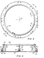
- struts 50 are also secured to the annular member 14 as seen in FIGURE 4.
- Each strut 50 includes a base 52 rigidly secured to the wrapping sprocket 14.
- a socket 54 is pivoted to the base 52 through bolt 56.
- the socket 54 includes a flange 57 with a threaded hole to receive a threaded bolt 58.
- the threaded bolt permits the angle of the socket 54 relative to axis 18 to be varied.
- a rod 60 fits within an aperture in the socket 54 and is secured therein by a clamp assembly 62.
- a ring clamp assembly 64 is secured at the end of rod 60 opposite the socket 54.
- Each strut 50 clamps onto a rigid circular ring 66 through ring clamp assembly 64 as best seen in FIGURE 4.
- the ring 66 can be formed of a single length of rod bent into a circle with its free end secured by a clamp 68 as seen in FIGURE 3.
- the ring 66 supports a brace arm assembly 69, best seen in FIGURE 5, which includes a brace arm 70 which can be clamped in a fixed relationship to the ring by tightening bolt 72. It is clear from FIGURE 5 that the brace arm 70 can be oriented in any position desired relative to the ring 66 before tightening the bolt 72.
- the brace arm 70 and rod 44 adjacent thereto are interconnected by the remaining pieces of brace arm assembly 69, a collar 74 and collar 76.
- the collar 74 slides over a portion 75 of the bracket 70 and can be secured thereon by tightening a bolt 78.
- the collar 76 slides over the rod 44 and can be tightened thereon by a bolt 80.
- the collars 74 and 76 are pivotally connected by a bolt 82.
- the struts 50, ring 66 and brace arm assembly 69 provide a method for supporting the tape roll support spindles 34 against centrifugal forces generated by the rotation of the wrapping sprocket 14.
- the struts 50 extend radially toward the axis 18 from the wrapping sprocket 14 to the ring 66 to form a rigid mount for the ring 66.
- the adjustment bolts 58 can be adjusted to distribute the load on ring 66 uniformly to each strut 50 and support the ring concentric with axis 18.
- the struts 50 can be seen to lie on the surface of an imaginary conical surface having a locus on the axis 18.
- the pivotal connection between the collars 74 and 76 will permit the spindles 34 to be adjusted through adjustment screws 42 to a desired orientation relative to the axis 18.
- the various struts 50, ring 66 and brace arm assembly 69 act together with the tape roll support spindles 34 to define a number of trusses having significant strength to maintain the spindle fixed during rotation.
- the collars 74 and 76 are readily adjustable and movable from one spindle to another.
- the spindle of FIGURE'S may need to be supported by the collars while the spindle of FIGURE 6 does not.
Landscapes
- Unwinding Webs (AREA)
- Lining Or Joining Of Plastics Or The Like (AREA)
Applications Claiming Priority (2)
| Application Number | Priority Date | Filing Date | Title |
|---|---|---|---|
| US06/483,882 US4461429A (en) | 1983-04-11 | 1983-04-11 | Tape machine support |
| US483882 | 1990-02-23 |
Publications (1)
| Publication Number | Publication Date |
|---|---|
| EP0121674A1 true EP0121674A1 (en) | 1984-10-17 |
Family
ID=23921881
Family Applications (1)
| Application Number | Title | Priority Date | Filing Date |
|---|---|---|---|
| EP84101225A Ceased EP0121674A1 (en) | 1983-04-11 | 1984-02-07 | Tape machine support |
Country Status (7)
| Country | Link |
|---|---|
| US (1) | US4461429A (ja) |
| EP (1) | EP0121674A1 (ja) |
| JP (1) | JPS59190822A (ja) |
| AU (1) | AU2456384A (ja) |
| CA (1) | CA1209891A (ja) |
| IN (1) | IN160885B (ja) |
| NL (1) | NL8400800A (ja) |
Cited By (1)
| Publication number | Priority date | Publication date | Assignee | Title |
|---|---|---|---|---|
| US5589019A (en) * | 1992-03-09 | 1996-12-31 | Nv Raychem Sa | Method for applying covering material to an elongate substrate |
Families Citing this family (7)
| Publication number | Priority date | Publication date | Assignee | Title |
|---|---|---|---|---|
| GB9924901D0 (en) * | 1999-10-21 | 1999-12-22 | Stolt Comex Seaway As | Method and apparatus for laying elongate articles |
| US6789380B2 (en) * | 2001-10-24 | 2004-09-14 | Gene Mellott | Spiral wrapper for conduit ducts |
| DK176100B1 (da) * | 2004-02-24 | 2006-06-06 | 4M Globe Man Ltd | Fremgangsmåde og apparat til fiksering af et pelsdyrskind på en tane |
| US7784723B2 (en) * | 2007-09-11 | 2010-08-31 | Deepflex Inc. | Layered tape guide spool and alignment device and method |
| JP5393247B2 (ja) * | 2009-05-13 | 2014-01-22 | 株式会社ブリヂストン | テープ巻き付け装置、及びテープ巻き付け方法 |
| US8567170B2 (en) * | 2011-04-06 | 2013-10-29 | Plant Sciences, Inc. | Device and method for creating a planting rope from plant root material |
| KR102776788B1 (ko) | 2019-10-08 | 2025-03-11 | 삼성디스플레이 주식회사 | 표시 장치 |
Citations (3)
| Publication number | Priority date | Publication date | Assignee | Title |
|---|---|---|---|---|
| AT360288B (de) * | 1978-10-05 | 1980-12-29 | Wedekind Denso Chemie | In umfangsrichtung um eine rohrleitung auf laufraedern bewegbares wickelgeraet zum auf- bringen eines korrosionsschutzbandes |
| DE2951030A1 (de) * | 1979-12-19 | 1981-07-02 | Denso-Chemie Wedekind Kg, 5090 Leverkusen | Vorrichtung zum bearbeiten, insbesondere zum bewickeln der oberflaechen von langgestreckten, zylindrischen koerpern |
| US4322262A (en) * | 1980-03-03 | 1982-03-30 | T. C. Mfg. Co., Inc. | Apparatus for wrapping conduits with sheet material |
Family Cites Families (6)
| Publication number | Priority date | Publication date | Assignee | Title |
|---|---|---|---|---|
| US1852827A (en) * | 1928-12-27 | 1932-04-05 | Miller Rubber Company Inc | Tube mandrel chucking device |
| US3137985A (en) * | 1962-07-02 | 1964-06-23 | Gen Electric | Taping head |
| US3789594A (en) * | 1972-06-06 | 1974-02-05 | United States Steel Corp | Wrapping apparatus |
| GB1497834A (en) * | 1974-06-05 | 1978-01-12 | Montagut Guix J Salvador | Manufacture of elongated hollow bodies from fibre-reinforced synthetic resins |
| CA1151517A (en) * | 1980-02-05 | 1983-08-09 | Maurice N. Garneau | Pipe wrapping machine |
| US4426834A (en) * | 1981-12-14 | 1984-01-24 | Dokmo Richard C | Apparatus for wrapping conduit with sheet material |
-
1983
- 1983-04-11 US US06/483,882 patent/US4461429A/en not_active Expired - Fee Related
-
1984
- 1984-01-30 IN IN86/DEL/84A patent/IN160885B/en unknown
- 1984-01-31 CA CA000446467A patent/CA1209891A/en not_active Expired
- 1984-02-07 EP EP84101225A patent/EP0121674A1/en not_active Ceased
- 1984-02-08 JP JP59020112A patent/JPS59190822A/ja active Pending
- 1984-02-14 AU AU24563/84A patent/AU2456384A/en not_active Abandoned
- 1984-03-13 NL NL8400800A patent/NL8400800A/nl not_active Application Discontinuation
Patent Citations (3)
| Publication number | Priority date | Publication date | Assignee | Title |
|---|---|---|---|---|
| AT360288B (de) * | 1978-10-05 | 1980-12-29 | Wedekind Denso Chemie | In umfangsrichtung um eine rohrleitung auf laufraedern bewegbares wickelgeraet zum auf- bringen eines korrosionsschutzbandes |
| DE2951030A1 (de) * | 1979-12-19 | 1981-07-02 | Denso-Chemie Wedekind Kg, 5090 Leverkusen | Vorrichtung zum bearbeiten, insbesondere zum bewickeln der oberflaechen von langgestreckten, zylindrischen koerpern |
| US4322262A (en) * | 1980-03-03 | 1982-03-30 | T. C. Mfg. Co., Inc. | Apparatus for wrapping conduits with sheet material |
Cited By (1)
| Publication number | Priority date | Publication date | Assignee | Title |
|---|---|---|---|---|
| US5589019A (en) * | 1992-03-09 | 1996-12-31 | Nv Raychem Sa | Method for applying covering material to an elongate substrate |
Also Published As
| Publication number | Publication date |
|---|---|
| JPS59190822A (ja) | 1984-10-29 |
| NL8400800A (nl) | 1984-11-01 |
| AU2456384A (en) | 1984-10-18 |
| CA1209891A (en) | 1986-08-19 |
| US4461429A (en) | 1984-07-24 |
| IN160885B (ja) | 1987-08-15 |
Similar Documents
| Publication | Publication Date | Title |
|---|---|---|
| US4461429A (en) | Tape machine support | |
| US3976260A (en) | Transportable cable reel | |
| US4177734A (en) | Drive unit for internal pipe line equipment | |
| US4610403A (en) | Pipe tape tensioner | |
| JPH0526593B2 (ja) | ||
| JPH0353058B2 (ja) | ||
| US5346149A (en) | Adjustable pipe wrap machine | |
| US3012756A (en) | Tandem sheave stringing block | |
| US4061513A (en) | Wrapping apparatus for pipeline joints | |
| US4741490A (en) | Mandrel for applying wrapping material | |
| US20250011101A1 (en) | Conveyor scraper systems, methods and apparatus | |
| US6307135B1 (en) | Support leg of a bass drum | |
| US4021090A (en) | Ground wire connector | |
| JP3156560B2 (ja) | コルゲートチューブのスリット形成方法及び装置 | |
| JPH09222070A (ja) | サボニウス型風車 | |
| CN114976989A (zh) | 一种电线电缆安装用调紧装置 | |
| CN222168043U (zh) | 一种电缆成缆机的绕包装置 | |
| CN221922768U (zh) | 一种转动设备的定芯组件 | |
| US4264399A (en) | Material braking apparatus | |
| JP2023161092A (ja) | ケーブルドラム | |
| JPH0553575B2 (ja) | ||
| JP3244352U (ja) | コイル巻きされた線材の回転繰り出し装置 | |
| EP0021418B1 (en) | Material braking apparatus | |
| CN118117509B (zh) | 一种高压电缆穿管敷设方法 | |
| CN223073687U (zh) | 一种转动稳定的电缆线盘及线盘轴 |
Legal Events
| Date | Code | Title | Description |
|---|---|---|---|
| PUAI | Public reference made under article 153(3) epc to a published international application that has entered the european phase |
Free format text: ORIGINAL CODE: 0009012 |
|
| AK | Designated contracting states |
Designated state(s): DE FR GB IT |
|
| 17P | Request for examination filed |
Effective date: 19850228 |
|
| RAP1 | Party data changed (applicant data changed or rights of an application transferred) |
Owner name: CRC PIPELINE INTERNATIONAL, INC. |
|
| STAA | Information on the status of an ep patent application or granted ep patent |
Free format text: STATUS: THE APPLICATION HAS BEEN REFUSED |
|
| 18R | Application refused |
Effective date: 19870220 |
|
| RIN1 | Information on inventor provided before grant (corrected) |
Inventor name: HUNT, CHARLES WESLEY Inventor name: GOEKLER, ROBERT GERALD |