EP0121486A2 - Appareil et procédé de décoration d'objets - Google Patents
Appareil et procédé de décoration d'objets Download PDFInfo
- Publication number
- EP0121486A2 EP0121486A2 EP84420058A EP84420058A EP0121486A2 EP 0121486 A2 EP0121486 A2 EP 0121486A2 EP 84420058 A EP84420058 A EP 84420058A EP 84420058 A EP84420058 A EP 84420058A EP 0121486 A2 EP0121486 A2 EP 0121486A2
- Authority
- EP
- European Patent Office
- Prior art keywords
- article
- axis
- successive
- relative
- applicator
- Prior art date
- Legal status (The legal status is an assumption and is not a legal conclusion. Google has not performed a legal analysis and makes no representation as to the accuracy of the status listed.)
- Granted
Links
- 238000000034 method Methods 0.000 title claims abstract description 37
- 238000012546 transfer Methods 0.000 claims description 89
- 230000010365 information processing Effects 0.000 claims description 18
- 238000013519 translation Methods 0.000 claims description 17
- 238000005096 rolling process Methods 0.000 claims description 15
- 238000007639 printing Methods 0.000 description 46
- 239000011888 foil Substances 0.000 description 16
- 238000005034 decoration Methods 0.000 description 8
- 230000008569 process Effects 0.000 description 7
- 238000006073 displacement reaction Methods 0.000 description 4
- 238000004519 manufacturing process Methods 0.000 description 4
- 230000004044 response Effects 0.000 description 4
- 239000000523 sample Substances 0.000 description 3
- 238000007650 screen-printing Methods 0.000 description 3
- 230000008878 coupling Effects 0.000 description 2
- 238000010168 coupling process Methods 0.000 description 2
- 238000005859 coupling reaction Methods 0.000 description 2
- 238000010586 diagram Methods 0.000 description 2
- 238000002372 labelling Methods 0.000 description 2
- 230000007246 mechanism Effects 0.000 description 2
- 238000004806 packaging method and process Methods 0.000 description 2
- 230000001105 regulatory effect Effects 0.000 description 2
- 238000003860 storage Methods 0.000 description 2
- 241001674048 Phthiraptera Species 0.000 description 1
- 230000008859 change Effects 0.000 description 1
- 238000010276 construction Methods 0.000 description 1
- 230000001276 controlling effect Effects 0.000 description 1
- 230000003247 decreasing effect Effects 0.000 description 1
- 230000002939 deleterious effect Effects 0.000 description 1
- 238000013461 design Methods 0.000 description 1
- 230000000977 initiatory effect Effects 0.000 description 1
- 239000000463 material Substances 0.000 description 1
- 230000009467 reduction Effects 0.000 description 1
- 230000035945 sensitivity Effects 0.000 description 1
- 238000004804 winding Methods 0.000 description 1
Images


Classifications
-
- B—PERFORMING OPERATIONS; TRANSPORTING
- B41—PRINTING; LINING MACHINES; TYPEWRITERS; STAMPS
- B41F—PRINTING MACHINES OR PRESSES
- B41F15/00—Screen printers
- B41F15/08—Machines
- B41F15/089—Machines for printing on essentially spherical surfaces
Definitions
- the present invention relates generally to decorating aticles, such as bottles and other containers, and pertains, more specifically, to printing, labelling or otherwise applying a decorating medium to the external surface of such an article when the article has a non-circular cross-sectional configuration.
- article decorating apparatus and method are disclosed in United States Patent No. 3,247,786 to Heyne et al for decorating the external surface of containers having a non-circular cross-sectional configuration.
- the Heyne et al apparatus relies upon specially contoured gears and cams which must be provided for each particular cross-sectional configuration, thereby reducing the economy and flexibility of handling a wide variety of shapes and sizes with a single machine.
- the apparatus disclosed in United States Patent No. 3,249,043 to Karlyn et al which can decorate certain non-circular surface contours, also relies upon individualized mechanical components, such as gears and levers, which are specifically tailored to each surface contour to be decorated.
- Another object of the invention is to provide apparatus and method in which the external surface contour of a particular article to be decorated itself may be utilized to set up the apparatus for decorating that surface contour.
- Still another object of the invention is to provide apparatus and method for decorating the external surface of articles even where the external surface follows no particular regular mathematical shape and may have an unusual configuration.
- Yet another object of the invention is to provide apparatus and method for decorating the external surface of containers and like articles having a non-circular cross-sectional configuration and which will do so economically, even for short production runs, with minimal set-up time and maximum flexibility in the variety of shapes and sizes to be accomodated.
- a further object of the invention is to provide apparatus and method for decorating the external surface of an article, and in which the contour of the surface first is detected to provide information for operating the apparatus to apply a decorating medium to articles of lice surface contour.
- a still further object of the invention is to provide apparatus and method for decorating the external surface of an article of non-circular cross-sectional configuration and which enables automatic conformation to almost any selected surface contour to be decorated, with minimal operator skill.
- Yet a further object of the invention is to provide apparatus and method for decorating the external surface of an article of non-circular cross-sectional configuration with increased ease and consistent high quality.
- the apparatus including an applicator having a surface for applying a decorating medium to the article surface at successive corresponding portions of the article surface and the applicator surface, with the applicator surface and the article surface maintained in proper relative position and appropriate relative velocity for the application of the decorating medium, throughout a decorating cycle of operation, the apparatus and method comprising: positioning means for and the step of positioning the article and the applicator at successive positions relative to one another during the decorating cycle such that successive portions of the article surface will be placed in the proper relative position and at the appropriate relative velocity with corresponding successive portions of the applicator surface throughout the decorating cycle, the positioning means including drive means for placing the successive portions of the article surface and the successive portions of the applicator surface at the successive positions during the decorating cycle; detecting means for and the step of detecting the successive relative positions of the article and the applicator at which the successive portions of the
- Bottle 20 is a typical example of the large variety.of containers available for the packaging and sale of a myriad of products and illustrates only one of many available shapes.
- the outer surface 22 of bottle 20 is to be decorated, or labelled, to display artwork and text associated with the promotion of the product packaged in the bottle.
- the desire for attractive packaging leads to the need for versatile decorating techniques which will place a decorating medium along any selected portion of the outer surface 22 with accuracy and consistent high quality, regardless of the contour of the outer surface 22.
- Bottle 20 includes a closed base 24 and an opposite neck 26 having an open mouth 28.
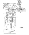
- Apparatus 30 is illustrated which is constructed in accordance with the present invention and carries out the method of the invention in decorating the outer surface of an article having a non-circular cross-sectional configuration, as illustrated by bottle 20.
- Apparatus 30 includes a printing machine 32, which will apply a decorating medium in the form of printing ink to the outer surface 22 of bottle 20, and a control arrangement 34, which will control the operation of the printing machine 32, as will be explained in detail below.
- Printing machine 32 includes a main frame 36 which carries the various mechanisms for accomplishing printing, while control arrangement 34 includes a control frame 38 upon which is carried a variety of controls.
- bottle 20 is placed within printing machine 32 at a given location, designated as printing station 40, where there is located a chuckinr fixture 41 which includes a socket 42 carried by a spindle 44 for receiving the base 24 of bottle 20, and a tapered free center 46 carried by a rod 48 for entry into the open mouth 28 of the bottle 20.
- An actuator 50 selectively moves the rod 48 longitudinally, as indicated by the arrow thereon, to seat the center 46 within mouth 28 and thereby clamp the bottle 20 in place within the chucking fixture 41 at printing station 40.
- Chucking fixture 41 is mounted upon a work table 52 which is integral with a carriage 54 which carries a first drive motor 56 coupled to the spindle 44 for rotation of the spindle 44, and consequently the bottle 20, about a longitudinal axis Z, the free center 46 being freely rotatable upon rod 48.
- Carriage 54 rides upon a pair of rails 58 secured to a platform 60-upon which there is mounted a second drive motor 62 coupled to a first lead screw 64 which extends through a follower 66 carried by carriage 54 such that actuation of the drive motor 62 will move the carriage 54 along rails 58 in the direction of a second axis X which is horizontal and perpendicular to longitudinal axis Z.
- Platform 60 itself is supported by a pair of vertical support shafts 70 slideably received within sleeves 72 fixed to frame 36 of printing machine 3 2.
- a third drive motor 74 is mounted upon frame 36 by means of a bracket 75 and is coupled to a second lead screw 76 which carries a follower 78 movable along the lead screw 76 in response to rotation of the lead screw 76.
- a yoke 80 is integral with follower 78 and is affixed to each support shaft 70 at collar 82 to couple the platform 60 for movement with the follower 78 upon rotation of lead screw 76 in response to actuation of drive motor 74. Movement of the platform 60 is along a direction parallel to a third axis Y which is vertical and perpendicular to axes Z and X.
- work table 52, and consequently bottle 20 is movable along orthogonal axes X and Y and bottle 20 is rotatable about axis Z which is perpendicular to axes X and Y.
- printing machine 32 employs a screen printing arrangement of the type well-known in the decoration of bottles.
- a framed screen 90 is secured to a sub-frame 92 by means of clamps 94 carried by a screen carriage 96 mounted for movement along a pair of guides 98 affixed to main frame 36 and extending parallel to the X axis.
- a further drive motor 100 is mounted upon the main frame 36 and drives a pinion gear 102, through a reduction gear train 104, which pinion gear 102 is meshed with a toothed rack 106 secured to the screen carriage 96 such that upon actuation of drive motor 100, screen carriage 96, and consequently screen 90, will move along directions parallel to the X axis, relative to the printing station 40.
- a squeegee 110 is held in a holder 112 affixed to a carrier rod 114 which is selectively moved downwardly or upwardly, into or out of printing relationship with screen 90, by means of an actuator assembly 116 carried by frame 36.
- printing is accomplished by the transfer of ink through the screen 90, assisted by the squeegee 110, to the bottle 20 at a point of transfer 120 in the printing station 40.
- bottle 20 had a circular cross-sectional configuration
- printing could be accomplished merely by moving the screen 90 along the direction of the X axis while rotating the bottle about the Z axis in synchronism so that the surface of the screen 90 acting in conjunction with the surface of the squeegee 110, referred to as the applicator surface, and the outer surface 22 of bottle 20 are in proper relative position for the accurate registration of the printed matter and are in appropriate relative velocity for the accurate transfer of ink through the screen to the bottle; that is, the surface speeds and directions are matched to essentially eliminate relative velocity at point of transfer 120.
- a bottle 20' of circular cross-section may be rotated about the Z axis in a counterclockwise direction while the screen 90 is moved in a direction from right to left, parallel to the X axis, and squeegee 110 remains stationary, to accomplish the transfer of ink, through screen 90, at the point of transfer 120.
- the positions of the applicator surface and the article surface relative to one another, and the speed of those surfaces must be such that contact is made at the point of transfer and there is essentially no relative velocity between the surfaces at the point of transfer.
- the cross-sectional configuration of bottle 20 is not circular and the attainment of the proper relative position of the applicator surface and the bottle surface at point of transfer 120, as well as the attainment of the appropriate relative velocity for the application of ink, requires lateral displacement of the Z axis of rotation of bottle 20, in the directions of the X and Y axes, in synchronism with rotation of the bottle 20 about the Z axis and movement of the screen 90.
- FIGS. 8 through 11 there is illustrated diagrammatically a portion of the decorating cycle necessary to decorate the surface of the elliptical cross-sectional configuration of bottle 20.
- FIG. 8 through 11 there is illustrated diagrammatically a portion of the decorating cycle necessary to decorate the surface of the elliptical cross-sectional configuration of bottle 20.
- bottle 20 and screen 90 are shown at a starting or home position, with the squeegee 110 placed against screen 90 at the point of transfer 120.
- the Z axis is displaced to position Z 4 , still maintaining the bottle surface tangent to the screen at point of transfer 120, as seen in FIG. 11.
- FIGS. 8 through 11 show one-quarter of a revolution of bottle 20, but the principles are the same for the remaining three-quarters of a revolution necessary to traverse the complete surface of the bottle and return the bottle to the starting or home position.
- the Z axis is moved in accordance with the configuration of the surface of the bottle to maintain the surface tangent to the screen at the point of transfer 120 regardless of the angular position of the bottle.
- the speed of rotation of the bottle 20, together with the speed of translation of the Z axis along the X and Y axes is regulated so that the speed of the portion of the bottle surface at point of transfer 120 essentially matches the speed of the screen 90 to attain essentially zero relative velocity at the point of transfer 120.
- each angular position of the bottle 20 about the Z axis has a corresponding point on the outer surface 22 which when brought tangent to the screen 90 at point of transfer 120 will place the Z axis at a particular position relative to the X and Y axes.
- there is a speed of movement of the chosen point which when appropriately matched to the speed of movement of screen 90 will attain essentially zero relative velocity.
- printing machine 32 enables movement of the Z axis along directions parallel to the X and Y axes, as well as rotation of the bottle about the Z axis; hence, information pertaining to the location of the Z axis and the speed of movement of the bottle surface at that location, expressed in terms of distances along the X and Y axes and the angular position around the Z axis, for points along the surface of the bottle, can be used to operate the printing machine 32 to accomplish the desired decoration of the surface of bottle 20.
- FIG. 12 as well as to FIGS. 3, 4 and 5, a generally schematic diagram illustrates the operation of printing machine 32 by control arrangement 34. As described above, in connection with FIGS.
- bottle 20 is held in chucking fixture 41 with the outer surface 22 of the bottle 20 placed at the point of transfer 120.
- the screen 90 and squeegee 110 also are located at the point of transfer 120.
- the bottle 20 is rotated by the operation of drive motor 56.
- the Z axis is translated laterally in directions parallel to the X and Y axes by operation of drive motors 62 and 74, respectively, to maintain the portion of outer surface 22 located at the point of transfer 120 tangent to the screen 90 and at essentially zero velocity relative to the screen 90 which itself is advanced simultaneously by the operation of drive motor 100.
- drive motors 56, 62 and 74 serve as positioning means to position the outer surface 22 of bottle 20 relative to the point of transfer 120.
- each drive motor 56, 62 and 74 is actuated by a corresponding drive control 130, 132 and 134, respectively, which, in turn, is interfaced through interface 136 with an information processing means in the form of microprocessor 140.
- Drive motor 100 is actuated by a drive control 142 which includes a speed selector 143 and which is connected to interface 136 through a control relay 144, while the actuator 50 of chucking fixture 41 and the actuator assembly 116 for squeegee 110 are operated by an actuator assembly control 146 connected to interface 136 through another control relay 148.
- Appropriate sensing and limit switches 150 are placed in suitable locations in printing machine 32 and connected to interface 136.
- An operator means here shown in the form of an alpha-numeric keyboard 152, operates the microprocessor 140, and a display 154 may be provided to aid in the programming and operation of the microprocessor 140.
- a separate information storage device 156 may be utilized to store information to be utilized in the operation of the apparatus.
- Microprocessor 140 is programmed to process information pertaining to the cross-sectional configuration of the bottle 20 and information pertaining to the condition of the positioning means which positions the bottle 20 relative to the screen 90 at the point of transfer 120 so as to provide operating information to the positioning means, which operating information enables the positioning means to maintain the proper relative position and the appropriate relative velocity between the bottle surface 22 and the screen 90 at the point of transfer 120 during a decorating cycle.
- the information pertaining to the condition of the positior ing means is in the form of the location of the Z axis in terms of the distance along the X axis and Y axis from a given reference point, in this instance the reference point being a home position which coincides with the intersection of the X and Y axes, or the ) origin of the orthogonal coordinates provided by the X and Y axes,! and the angular position of the bottle 20 about the Z axis, as referenced to a starting or home position.
- the reference point being a home position which coincides with the intersection of the X and Y axes, or the ) origin of the orthogonal coordinates provided by the X and Y axes,! and the angular position of the bottle 20 about the Z axis, as referenced to a starting or home position.
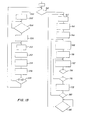
- a program flowchart 160 illustrates the operation of the apparatus 30 through a decorating cycle.
- drive motors 56, 62 and 74 are stepping motors and the position information for each point along the outer surface 22 of bottle 20 is furnished by the microprocessor 140 in terms of increments of movement of each drive motor, relative to the starting or home position, necessary to reach that point and place that point in the proper relative position and appropriate relative velocity at the point of transfer 120.
- the velocity information for each point also is supplied by the microprocessor 140 in terms of increments of movement within a specified time.
- microprocessor 140 is provided with position and velocity information for four hundred points along the outer surface 22 of bottle 20, corresponding to four hundred increments of rotation of the bottle about the Z axis, in a manner which will be explained in detail hereinafter. Suffice it to say at this juncture that for the given elliptical contour of outer surface 22 of bottle 20, microprocessor 140 is provided with information defining four hundred points spaced around the full perimeter of the elliptical cross-sectional configuration, corresponding to four hundred increments of rotation of the bottle 20 about the Z axis. While the number of increments of rotation is four hundred in the illustrated embodiment, the choice of the number of increments may be varied in accordance with the specific requirements of articles of various sizes and shapes.
- Bottle 20 is placed manually within the chucking fixture 41 by an operator. The operator then selects the print mode, utilizing control arrangement 34, and the microprocessor 140 operates so that actuator 50 will clamp bottle 20 in place. Then, drive motors 56, 62 and 74 will be actuated to rotate the bottle about the Z axis and laterally translate the Z axis parallel to the X and Y axes until the home position is reached, if the components were not already in the home position, as indicated at block 162 of the flowchart 160.
- the program continues to operate the microprocessor 140 through a print initation command 164 which actuates the squeegee control to move the squeegee downward into a print position at the point of transfer 120 and actuates drive motor 100 to commence movement of the screen 90 through the point of transfer 120, and a first point set command 166 sets an indexing pointer of the microprocessor to the memory location of the first of the four hundred points
- a print initation command 164 which actuates the squeegee control to move the squeegee downward into a print position at the point of transfer 120 and actuates drive motor 100 to commence movement of the screen 90 through the point of transfer 120
- a first point set command 166 sets an indexing pointer of the microprocessor to the memory location of the first of the four hundred points
- the position information and velocity information are obtained from the information provided to the microprocessor, as indicated at 168.
- the drive motor 56 then is actuated to rotate the bottle through one increment about the Z axis, as indicated at 170, and the drive motors 62 and 74 are actuated to move the Z axis to place the first point on the outer surface 22 in the proper relative position and at the appropriate relative velocity with respect to the squeegee 110 and the moving screen 90 at the point of transfer 120, as indicated at 172, 174 and 176.
- the pointer is incremented to the next point, as indicated at 178, and the routine for incrementing and moving the Z axis is repeated for the second point.
- the routine is repeated for each successive point until all four hundred points have been treated, as indicated at 180, and the decorating cycle is complete.
- the operator may then enter a signal, as shown at 182, to return all components to the home position, and start the program again for a subsequent bottle. It is pointed out that the increments of movement of the bottle relative to the Z, X and Y axes are so arranged in sequence that the total movement relative to each of the Z, X and Y axes takes place almost simultaneously, when viewed from the standpoint of the rate of transfer of the decorating medium at point of transfer 120.
- apparatus 30 is capable of decorating articles of various cross-sectional configurations. All that is required is that microprocessor 140 be provided with information which will define the surface configuration of the particular article to be decorated, in terms of the positioning of the article relative to the X, Y and Z axes.
- apparatus 30 is placed into a learning configuration and microprocessor 140 operates the apparatus in a learning mode, as follows.
- FIG. 14 the screen 90 and squeegee 110 have been removed from the printing machine 32 and a detecting means, shown in the form of a simple electrical switch 190, has been mounted upon the printing machine 32 at the printing station 40.
- Switch 190 has a sensing probe 192, the tip 194 of which is located at the point of transfer 120.
- bottle 20 is placed in the chucking fixture 41, it being understood that the article placed in the chucking fixture may be of any one of various sizes and shapes and that the configuration of component parts of the chucking fixture may be modified accordingly to accommodate the various sizes and shapes.
- microprocessor 140 is operated in the learning mode, as illustrated at 200 in FIG. 13.
- the operator selects the learning mode and the program proceeds to place the Z axis in the home position, at the origin of the X and Y axes, as illustrated by 202, if the Z axis is not already at home.
- the program then assures that the switch 190 is in place, as indicated at 204, before proceeding.
- all previous information is cleared, as indicated at 206, and the program proceeds to obtain information pertaining to the cross-sectional configuration of bottle 20.
- the Z axis is translated laterally, in the direction of the X and Y axes, until the switch 190 indicates that a portion of the surface 22 of bottle 20 located at a point corresponding to that one angular position is tangent to reference plane RP (see FIG. 14), which is the plane of the screen 90, at the point of transfer 120.
- reference plane RP see FIG. 14
- the particular sub-routine for determining the X and Y positional information.defining each point of tangency corresponding to each angular position of the article about the Z axis, as indicated at 210, will be described in greater detail below.
- the positional information is stored, as shown by 212, and is then employed in a velocity calculation, as indicated by 214.
- the velocity calculation is based upon the differences in the X and Y distances, as well as the position of the Z axis, for consecutive points of tangency, the differences being a measure of the linear travel of the segment or portion of outer surface 22 which will pass the point of transfer 120 between the consecutive points of tangency.
- the amount of linear travel thus establishes the speed at which the Z axis must be displaced along the X and Y directions and the speed at which the bottle 20 is to be rotated about the Z axis in order to present a constant surface speed to the point of transfer during the print mode of operation.
- the velocity information is stored, together with the positional information.
- the bottle 20 is rotated in increments about the Z axis, as indicated at 218, to the next consecutive angular position and the routine is repeated, as noted at 220, until position and velocity information is stored for all four hundred angular positions about the Z axis.
- the stored information then is utilized by the microprocessor to operate apparatus 30 in the print mode, as described above.
- the particular sub-routine for determining the point of tangency so as to derive the position and velocity information for a particular cross-sectional configuration is illustrated in FIGS. 15 and 16.
- the sub-routine operates on the basis that for any angular position of the bottle 20 about the Z axis, the point on the outer surface 22 at which that surface will be tangent to the reference plane RP (the plane of the screen 90) is the point nearest to the reference plane (the highest point on the surface) and when that point is placed in coincidence with the point of transfer 120, the location of the Z axis, in terms of X and Y distances, will provide the required position information.
- the switch 190 will detect the coincidence of the point of tangency with the point of transfer 120, as follows.
- bottle 20 is in the home position with the Z axis at the origin of the X and Y axes and the tip 194 of plunger 192 of switch 190 placed at the point of transfer 120 and in contact with the outer surface 22 at point T l in reference plane RP.
- the cross-sectional configuration of bottle 20 is an ellipse and, in the illustrated home position, outer surface 22 is tangent to plane RP at point T 1 and switch 190 is closed.
- the portion of surface 22 at the point of transfer 120 no longer is tangent to the plane RP.
- the sub-routine for moving the Z axis to that position is illustrated in FIG. 16.
- the drive motor 74 is actuated to move the Z axis downwardly (in the -Y direction), in counted increments, until switch 190 opens.
- the Z axis is moved upwardly (in the +Y direction) until switch 190 closes.
- drive motor 62 is actuated to move the Z axis to the left, as viewed in FIG. 15 (in the -X direction), in counted increments until switch 190 opens.
- the Z axis is moved to the right (in the +X direction) until the switch 190 closes.
- the tip 194 of plunger 192 is located at point R, to the right of the highest point of surface 22, as shown in VIEW C of FIG. 15.
- the Z axis is moved to the right (in the +X direction) in increments which are counted by a separate counter W until switch 190 opens, and then is moved left again (in the -x direction) until the switch 190 closes.
- the tip 194 plunger 192 is located at point L, to the left of the highest point of surface 22, as illustrated in VIEW D. of FIG. 15.
- Points L and R define a chord LR, the length of which is recorded in counter W.
- the Z axis is moved to the left again (in the -X direction) while decrementing counter W by two for each increment of movement until counter W is emptied.
- the midpoint of chord LR is located approximately at the point of transfer 120, as seen in VIEW E of FIG. 15. Since the midpoint of chord LR is aligned vertically essentially with the highest point of surface 22, the Z axis now is moved downwardly (in the -Y direction) until switch 190 opens and then is moved upwardly (in the +Y direction) until switch 190 closes, at which position the surface 22 is essentially tangent with plane RP at point T 2 which coincides with the point of transfer 120, as shown in VIEW F of FIG. 15.
- the position of the Z axis thus is determined in terms of X and Y distances.
- sufficient position information is provided, in terms of X and Y distances, to define the surface contour of the cross-sectional configuration of bottle 20.
- the sub-routine approximates the location of point T 2 by virtue of the fact that chord LR is divided in half, but the segment of surface 22 lying between points L and R is not necessarily symmetrical about the midpoint of chord LR.
- the approximation becomes more and more accurate as the length of chord LR is decreased.
- a decrease in the magnitude of each increment of movement of the Z axis and an increase in the sensitivity of switch 190 will enable an even more accurate determination of the point of tangency T 2 , for all practical purposes.
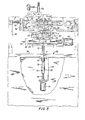
- another apparatus 230 is constructed in accordance with the invention and includes a printing machine 232 which will apply a decorating medium in the form of a label or roll leaf to the outer surface 22 of bottle 20 by heat transfer from a foil.
- apparatus 230 utilizes the same control arrangement 34 for controlling the operation of the printing machine 232; however, the control arrangement is provided with information pertaining to the operation required for applying the particular decorating medium utilized in connection with printing machine 232, as will be described below.
- printing machine 232 includes a main frame 236.
- Bottle 20 is placed within a chucking fixture 241 which includes a socket 242 carried by a spindle 244 for receiving the base 24 of bottle 20, and a tapered free center 246 carried by a rod 248 for entry into the open mouth 28 of the bottle 20.
- An actuator 250 selectively moves the rod 248 longitudinally, as indicated by the arrow thereon, to seat the center 246 within the chucking fixture 241.
- Chucking fixture 241 is mounted upon a work ' table 252 which is integral with a carriage 254 which carries a first drive motor 256 coupled to the spindle 244 for rotation of the spindle 244, consequently the bottle 20, about a longitudinal axis Z, the free center 246 being freely rotatable upon rod 248.
- Carriage 254 rides upon a pair of rails 258 secured to a platform 260 upon which there is mounted a second drive motor 262 coupled to a first lead screw 264 which extends through a follower 266 carried by carriage 254 such that actuation of the drive motor 262 will move the carriage 254 along rails 258 in the direction of a second axis X which is horizontal and perpendicular to longitudinal axis Z.
- Platform 260 itself is supported by a pair of vertical support shafts 270 slideably received within sleeves 272 fixed to frame 236 of printing machine 232.
- a third drive motor 274 is mounted upon frame 236 by means of a bracket 275 and is coupled to a second lead screw 276 which carries a follower 278 movable along the lead screw 276 in response to rotation of the lead screw 276.
- a yoke 280 is integral with follower 278 and is affixed to each support shaft 270 at collar 282 to couple the platform 260 for movement with the follower 278 upon rotation of lead screw 276 in response to actuation of drive motor 274.
- Movement of the platform 260 is along a direction parallel to a third axis Y which is vertical and perpendicular to axes Z and Y.
- work table 252 and consequently bottle 20 is movable along orthogonal axes X and Y and bottle 20 is rotatable about axis Z which is perpendicular to axes X and Y.
- the Y axis drive components namely, motor 274 and lead screw 276, are fixed to the frame 236 and the X axis drive components, namely, motor 262 and lead screw 264, are mounted for movement in Y directions by the Y axis drive components.
- printing machine 232 employs a foil printing arrangement of the type well-known in the decoration of bottles and similar articles.
- a heated die 290 is secured to main frame 236 by holders 292 and includes a die surface 294 which is stationary and, in the illustrated embodiment, carries the pattern of the printed matter to be applied to the surface 22 of bottle 20 and which, in this instance, lies in a plane RP.
- a heat transfer foil 296 is interposed between surface 22 of bottle 20 and die surface 294 and is supplied in the form of a strip of indeterminate length placed along a path 298 which extends through a point of transfer 300.
- Foil 296 is supplied from a supply roll 302, while exhausted foil is routed to a take-up roll 304, both of which rolls 302 and 304 are mounted upon main frame 236.
- Guide bars 306 and 308 assure that path 298 extends downwardly, away from the die surface 294, at each side of the point of transfer 300, in accordance with known practice in foil printing, the guide bars 306 and 308 being selectively positionable for the optimum path 298. It is noted that in order to place the bottle 20, die 290 and foil 296 in the appropriate relationship, as illustrated, bottle 20 and foil 296 initially are away from plane RP and then are moved into plane RP, and against die 290. Alternately, the apparatus may be modified to move die 290 and foil 296 initially away from plane RP and then into plane RP.
- bottle 20 had a circular cross-sectional configuration
- printing could be accomplished merely by moving the bottle along the direction of the X axis while rotating the bottle about the Z axis in synchronism so that the bottle is rolled along the stationary die surface 294, referred to as the applicator surface, such that the outer surface 22 of bottle 20 and the die surface 294 are in proper relative position for the accurate registration of the printed matter and are in appropriate relative velocity for the accurate transfer of leaf to the bottle; that is, simple rolling contact between the bottle surface and the die surface will eliminate relative velocity at the point of transfer 300, while assuring correct registration.
- bottle 20' of circular cross-section may be rotated about the Z axis in a counterclockwise direction while the Z axis (and the point of transfer 300) is translated in a direction from left to right, parallel to the X axis and plane RP, to accomplish the transfer of leaf from foil 296 to the outer surface of bottle 20' at point of transfer 300. Since the radius between the Z axis and the point of transfer 300 is constant for the circular cross-section, and since die surface 294 of die 290 is planar, the distance between the center of rotation of the bottle and the plane of the die surface, together with the position and speed of the bottle 20', may be maintained at a constant throughout the full decorating cycle.
- the cross-sectional configuration of bottle 20 is not circular and the attainment of the proper relative position of the applicator surface and the bottle surface at the point of transfer 300, as well as the attainment of the appropriate relative velocity for the application of leaf, requires lateral displacement of the Z axis of rotation of bottle 20, in the directions of the X and Y axes, in addition to the translation of the Z axis and point of transfer 300 in the direction of the X axis, in synchronism with rotation of the bottle 20 about the Z axis and translation of the Z axis in the direction of the X axis.
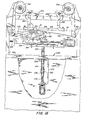
- FIG. 20 there is illustrated, largely diagrammatically, a decorating cycle effected to decorate the surface 22 of elliptical cross-sectional configuration of bottle 20.
- the Z axis is translated from left to right by movement of carriage 254 toward the right.
- the Z axis is displaced in directions parallel to the X and Y axes to maintain the bottle surface 22 essentially in rolling contact with foil 296 and the die surface 294, both of which are stationary, at the point of transfer 300, which also is translated in a direction parallel to the X axis.
- the Z axis thus is made to follow a path of travel 310 determined by the configuration of the surface of the bottle.
- the speed of rotation of the bottle 20, together with the speed of translation and displacement of the Z axis along the X and Y axes, is regulated so that the desired essentially rolling contact is maintained at the point of transfer 300.
- each angular position of the bottle 20 about the Z axis has a corresponding point on the outer surface 22 which when brought into rolling contact (tangent) with the die surface 294 at point of transfer 300 will place the Z axis at a particular position relative to the X and Y axes.
- there is a speed of movement of the chosen point which when appropriately matched to the speed of movement of the Z axis will attain essentially rolling contact (zero relative velocity between the chosen point and the die surface) at the point of transfer.
- printing machine 232 enables movement of the Z axis along directions parallel to the X and Y axes, as well as rotation of the bottle about the Z axis; hence, information pertaining to the location of the Z axis and the speed of movement of the bottle surface at that location, expressed in terms of distances along the X and Y axes and the angular position around the Z axis, for points along the surface of the bottle, can be used to operate the printing machine 232 to accomplish the desired decoration of the surface of bottle 20, as follows.
- Bottle 20 is held in chucking fixture 241 with the outer surface 22 of the bottle 20 placed at the point of transfer 300.
- the bottle 20 is rotated by the operation of drive motor 256.
- the Z axis is displaced laterally in directions parallel to the X and Y axes by operation of drive motors 262 and 274, respectively, to maintain the portion of outer surface 22 located at the point of transfer 300 tangent to the die surface 294 and at essentially zero velocity relative to the stationary die surface while the Z axis is translated simultaneously along the X axis by the operation of drive motor 262.
- drive motors 256, 262 and 274 serve as positioning means to position the outer surface 22 of bottle 20 relative to the point of transfer 300, and all are under the control of an information processing means in the form of a microprocessor, as described earlier.
- the microprocessor described hereinbefore is programmed to process information pertaining to the cross-sectional configuration of the bottle 20 and information pertaining to the condition of the positioning means which positions the bottle 20 relative to the die surface at the point of transfer 300 so as to provide operating information to the positioning means, which operating information enables the positioning means to maintain the proper relative position and the appropriate relative velocity between the bottle surface 22 and the die surface 294 at the point of transfer 300 during a decorating cycle.
- the information pertaining to the condition of the positioning means is in the form of the location of the Z axis in terms of the distance along the X axis and Y axis from a given reference point, in this instance the reference point being a home position which coincides with the intersection of the X and Y axes, or the origin of the orthogonal coordinates provided by the X and Y axes, and the particular position of the bottle 20 about the Z axis, as referenced to a starting or home position.
- the reference point being a home position which coincides with the intersection of the X and Y axes, or the origin of the orthogonal coordinates provided by the X and Y axes, and the particular position of the bottle 20 about the Z axis, as referenced to a starting or home position.
- the reference point being a home position which coincides with the intersection of the X and Y axes, or the origin of the orthogonal coordinates provided by the X and Y axes, and the particular position of
- apparatus 230 is capable of decorating articles of various cross-sectional configurations. All that is required is that the microprocessor be provided with information which will define the surface configuration of the particular article to be decorated, in terms of the positioning of the article relative to the X, Y and Z axes. In order to obtain the positional information for an article of a particular cross-sectional configuration, apparatus 230 is placed into a learning configuration, as follows.
- heated die 290 and foil 196 have been removed from the printing machine 232 and learning components have been mounted upon the printing machine 232.
- bottle 20 is placed in the chucking fixture 241, it being understood that the article placed in the chucking fixture may be of any one of various sizes and shapes and that the configuration of component parts of the chucking fixture may be modified accordingly to accommodate the various sizes and shapes.
- Bracket 312 includes a clevis 316 within which there is pivoted a bar 318 having a lower planar surface 320, corresponding to the die surface 294 and normally placed within plane RP, the same plane within which the die surface 294 lies when heated die 290 is in place for printing.
- Bracket 314 carries an indicator 322 which has a plunger 324 resiliently biased against bar 318 for indicating precisely when bar 318 is located at the position where lower surface 320 is in plane RP, referred to as the zero position.
- An essentially non-extensible, flexible member shown in the form of a cable 326 is wound around the outer surface 22 of bottle 20 for several turns 327, enough to couple the cable 326 with the outer surface 22 so that upon rotation of the bottle 20 about the Z axis there will be no slippage between the turns 327 of the cable 326 and the surface 22 of the bottle, when the cable 326 is tensioned between pins 328 which are secured to frame 236.
- a tensioning spring 330 is placed at one end of cable 326 while the other end of the cable 326 is attached to a resiliently biased plunger 332 of an indicator 334 affixed to respective pin 328.
- Indicator 334 provides an indication of precisely when segment 336 of the cable 326, extending between the bottle 20 and the indicator 334, is at a selected tension, referred to as the zero indication.
- the learning components identify the location of the Z axis, in terms of distances along the X and Y axes, when a corresponding point on the surface 22 of bottle 20 is located properly for transfer at plane RP, for each increment of rotation of the bottle about the Z axis, as follows.
- Bottle 20 With bottle 20 inserted within chucking fixture 241, lower surface 320 of bar 318 resting-against the surface 22 of bottle 20, and cable 326 wrapped around bottle 20 and tensioned between pins 328, the Z axis is located such that the lower surface 320 of bar 318 is within plane RP and the tension in segment 336 of cable 326 is at the selected tension, as indicated by indicators 322 and 334.
- Bottle 20 then is rotated about the Z axis through one increment of rotation. Since outer surface 22 of the bottle does not have a circular cross-sectional configuration, such rotation will cause bar 318 to pivot upwardly or downwardly, as shown in phantom in FIG. 21, thereby moving the lower surface 320 thereof out of the plane RP.
- Indicator 322 will indicate movement of the bar 318 away from the zero position.
- the tension in segment 336 will deviate from the selected tension due to winding and unwinding of the cable 326 around the bottle 20.
- the indications are transmitted to the microprocessor in the form of electrical signals at 340 and 342.
- the Z axis then is displaced in a direction parallel to the Y axis until the zero position is restored and the lower surface 320 of the bar 318, and consequently the surface 22 of the bottle 20, again are located in plane RP.
- the Z axis also is displaced in a direction parallel to the X axis until the selected tension is restored in segment 336 of cable 326, as indicated by the zero indication.
- the distances and directions along the X and Y axes needed to restore the zero position and the zero indication constitute the positional information defining the location of the point on the surface 22 of bottle 20 which is properly located at the plane RP and coincides with point of transfer 300.
- the information for that point is stored.
- Bottle 20 then is rotated about the Z axis through another increment and the process is repeated to obtain and store positional information for another point. The entire process is repeated until positional information is obtained and stored, preferably for four hundred angular positions of the bottle 20 about the Z axis, to complete one full revolution of the bottle.
- the learning components thus determine positional information which assures that a bottle of a particular cross-sectional configuration will maintain rolling contact at plane RP.
- velocity calculations are performed, as described hereinbefore, to establish the speed at which the bottle is to be rotated about the Z axis, as well as the speed at which the Z axis is to be translated and displaced along the X and Y directions, in order to maintain a generally constant surface speed. It is pointed out that, for most bottles or other articles to be decorated, where the surface contours do not change abruptly, approximations of the precise velocities are adequate since the velocity affects the roll rate and not the absolute position of the surface to be decorated, relative to the die surface. Thus proper registration is assured while dwell time may be varied somewhat without deleterious consequences, as long as proper rolling contact is maintained.
- the position and velocity information for almost any configuration of article may be learned directly from the article itself and utilized with ease to enable the decoration of articles having a wide variety of shapes and sizes by printing, labelling or other techniques requiring the same relationship between an applicator and the article surface to be decorated.
- the information for each article may be generated and then utilized immediately for short or long runs or may be stored in an information storage device, as illustrated at 156, for future use.
- apparatus 30 and 230 are not limited to a relatively few configurations defined by mechanisms which rely upon expensive cams, levers or special gears. The ability of the apparatus to learn a surface configuration from the article itself reduces the necessity for adhering precisely to shapes and sizes specified in manufacturing drawings for different containers.
- the apparatus and method lend themselves readily to compensation for greater dimensional tolerances commonly encountered in the decoration of multiple batches of manufactured articles. Since the learning and operating sequences are programmed for operation by a microprocessor, the apparatus is easy to use and will provide consistent high quality even when operated by operators having only limited skill. It will be apparent that the apparatus and method of the invention is equally applicable to a wide variety of printing processes including those in which preprinted matter is transferred by heat or pressure, as well as those described in connection with the illustrated embodiments.
Landscapes
- Engineering & Computer Science (AREA)
- Mechanical Engineering (AREA)
- Application Of Or Painting With Fluid Materials (AREA)
- Screen Printers (AREA)
Applications Claiming Priority (4)
| Application Number | Priority Date | Filing Date | Title |
|---|---|---|---|
| US481308 | 1983-04-01 | ||
| US06/481,308 US4469022A (en) | 1983-04-01 | 1983-04-01 | Apparatus and method for decorating articles of non-circular cross-section |
| US583174 | 1984-02-24 | ||
| US06/583,174 US4502380A (en) | 1983-04-01 | 1984-02-24 | Apparatus and method for decorating articles of non-circular cross-section |
Publications (3)
| Publication Number | Publication Date |
|---|---|
| EP0121486A2 true EP0121486A2 (fr) | 1984-10-10 |
| EP0121486A3 EP0121486A3 (en) | 1986-06-25 |
| EP0121486B1 EP0121486B1 (fr) | 1990-03-21 |
Family
ID=27046913
Family Applications (1)
| Application Number | Title | Priority Date | Filing Date |
|---|---|---|---|
| EP84420058A Expired EP0121486B1 (fr) | 1983-04-01 | 1984-03-26 | Appareil et procédé de décoration d'objets |
Country Status (3)
| Country | Link |
|---|---|
| US (1) | US4502380A (fr) |
| EP (1) | EP0121486B1 (fr) |
| DE (1) | DE3481698D1 (fr) |
Cited By (1)
| Publication number | Priority date | Publication date | Assignee | Title |
|---|---|---|---|---|
| DE4436275A1 (de) * | 1994-10-11 | 1996-04-25 | Kammann Maschf Werner | Siebdruckverfahren sowie Vorrichtung zu dessen Durchführung |
Families Citing this family (11)
| Publication number | Priority date | Publication date | Assignee | Title |
|---|---|---|---|---|
| DE3730409A1 (de) * | 1987-09-10 | 1989-03-23 | Balsfulland Gmbh Maschf Geb | Siebdruckmaschine |
| US4910661A (en) * | 1987-12-14 | 1990-03-20 | Edgar L. Barth | Method and apparatus for decorating cakes and other foods |
| US4889050A (en) * | 1988-09-29 | 1989-12-26 | Permanent Label Corporation | Apparatus and method for decorating tubular containers and like items |
| DE3936157C2 (de) * | 1989-10-31 | 1999-03-18 | Kammann Maschf Werner | Verfahren und Vorrichtung zum Bedrucken von Objekten |
| US5198059A (en) * | 1991-06-14 | 1993-03-30 | United Silicone Inc. | Method and apparatus for decorating articles of non-circular cross-section |
| US5454307A (en) * | 1995-02-07 | 1995-10-03 | Chen; Jin-Bin | Apparatus for printing shoe sole |
| US5711217A (en) * | 1995-09-18 | 1998-01-27 | Ser-Tek Systems, Inc. | Vector screen printing method and apparatus |
| US5795395A (en) * | 1997-03-07 | 1998-08-18 | Ben-Matitayhu; Ruth | Cake decorating system and method |
| US5970864A (en) * | 1998-05-06 | 1999-10-26 | Svec; Daniel C. | Stenciling device with registration apparatus |
| US6237486B1 (en) * | 2000-02-15 | 2001-05-29 | Gregory S. Firth | Screen printing apparatus and method for curved laminated skateboards |
| DE102021117878B4 (de) * | 2021-07-12 | 2024-07-04 | Packsys Global Ag | Vorrichtung und Verfahren zum Verzieren und/oder Etikettieren von rotationssymmetrischen, abschnittsweise kegelstumpfförmigen Gegenständen |
Citations (6)
| Publication number | Priority date | Publication date | Assignee | Title |
|---|---|---|---|---|
| US3247786A (en) * | 1961-07-20 | 1966-04-26 | Owens Illinois Glass Co | Article decorating |
| US3249043A (en) * | 1964-09-16 | 1966-05-03 | William M Karlyn | Apparatus for stenciling oval articles |
| BE690386A (fr) * | 1965-12-22 | 1967-05-02 | ||
| US3970831A (en) * | 1974-02-11 | 1976-07-20 | Goldsworthy Engineering, Inc. | Digitizing system for tape placement apparatus |
| FR2435329A1 (fr) * | 1978-07-10 | 1980-04-04 | Ass Ouvriers Instr Precision | Manipulateur, en particulier automate de peinture, susceptible d'apprentissage |
| GB1571893A (en) * | 1977-12-07 | 1980-07-23 | Hall Automation Ltd | Automatic processing apparatus |
Family Cites Families (1)
| Publication number | Priority date | Publication date | Assignee | Title |
|---|---|---|---|---|
| US4057893A (en) * | 1976-04-07 | 1977-11-15 | Still-Walter Tool & Manufacturing Company | Milling table lathe |
-
1984
- 1984-02-24 US US06/583,174 patent/US4502380A/en not_active Expired - Lifetime
- 1984-03-26 EP EP84420058A patent/EP0121486B1/fr not_active Expired
- 1984-03-26 DE DE8484420058T patent/DE3481698D1/de not_active Expired - Lifetime
Patent Citations (6)
| Publication number | Priority date | Publication date | Assignee | Title |
|---|---|---|---|---|
| US3247786A (en) * | 1961-07-20 | 1966-04-26 | Owens Illinois Glass Co | Article decorating |
| US3249043A (en) * | 1964-09-16 | 1966-05-03 | William M Karlyn | Apparatus for stenciling oval articles |
| BE690386A (fr) * | 1965-12-22 | 1967-05-02 | ||
| US3970831A (en) * | 1974-02-11 | 1976-07-20 | Goldsworthy Engineering, Inc. | Digitizing system for tape placement apparatus |
| GB1571893A (en) * | 1977-12-07 | 1980-07-23 | Hall Automation Ltd | Automatic processing apparatus |
| FR2435329A1 (fr) * | 1978-07-10 | 1980-04-04 | Ass Ouvriers Instr Precision | Manipulateur, en particulier automate de peinture, susceptible d'apprentissage |
Cited By (3)
| Publication number | Priority date | Publication date | Assignee | Title |
|---|---|---|---|---|
| DE4436275A1 (de) * | 1994-10-11 | 1996-04-25 | Kammann Maschf Werner | Siebdruckverfahren sowie Vorrichtung zu dessen Durchführung |
| US5651308A (en) * | 1994-10-11 | 1997-07-29 | Werner Kammann Maschinenfabrik Gmbh | Apparatus for printing on individual articles |
| DE4436275C2 (de) * | 1994-10-11 | 1998-08-27 | Kammann Maschf Werner | Verfahren und Vorrichtung zum Bedrucken von Einzelobjekten |
Also Published As
| Publication number | Publication date |
|---|---|
| US4502380A (en) | 1985-03-05 |
| DE3481698D1 (de) | 1990-04-26 |
| EP0121486A3 (en) | 1986-06-25 |
| EP0121486B1 (fr) | 1990-03-21 |
Similar Documents
| Publication | Publication Date | Title |
|---|---|---|
| US4469022A (en) | Apparatus and method for decorating articles of non-circular cross-section | |
| US4502380A (en) | Apparatus and method for decorating articles of non-circular cross-section | |
| CA2645195C (fr) | Systeme de decoration a grande vitesse | |
| US4889050A (en) | Apparatus and method for decorating tubular containers and like items | |
| CA1276499C (fr) | Machine d'impression sur articles par voie de serigraphie | |
| US7191574B2 (en) | Machine for wrapping groups of products with tubular lengths of stretch film | |
| US5207156A (en) | Process and apparatus for printing on articles | |
| US8322279B2 (en) | Marking or labeling machine and method | |
| DE69121693D1 (de) | Transfervorrichtung für Gegenstände | |
| EP0691303A1 (fr) | Doseuse adaptée au remplissage de flacons de dimensions variées | |
| US4100667A (en) | Method and means for loading film cartridges | |
| US3878026A (en) | Electrical component sequencer and taper | |
| US4483490A (en) | Individual coil winder with automatic coil change | |
| US4118915A (en) | Apparatus for automatically applying tubing around an object | |
| EP0324857A1 (fr) | Machine de moulage et etiqetage de recipients creux par etirage-soufflage | |
| US6192656B1 (en) | Method of and apparatus for packaging cylindrical article | |
| US4854147A (en) | Wire pinch mark applicator | |
| US5139599A (en) | Method for decorating articles having a conical surface | |
| US5887778A (en) | Method of and apparatus for welding surgical needle stock to a metal tape | |
| US5301608A (en) | Index control system for printing apparatus | |
| US5984085A (en) | Apparatus and method for the adjustment of workpiece carriers in automatic production lines | |
| IE52999B1 (en) | Method of and apparatus for sticking a multiplicity of ornamental pieces onto a base sheet material | |
| AU702113B2 (en) | Bag gripping and transfer apparatus and method | |
| CA1291726C (fr) | Methode et dispositif d'etiquetage de surfaces courbes | |
| EP0094471B1 (fr) | Dispositif pour transférer et replacer des rouleaux de matière textile en particulier pour des machines de matelassage |
Legal Events
| Date | Code | Title | Description |
|---|---|---|---|
| PUAI | Public reference made under article 153(3) epc to a published international application that has entered the european phase |
Free format text: ORIGINAL CODE: 0009012 |
|
| AK | Designated contracting states |
Designated state(s): DE FR GB IT |
|
| PUAL | Search report despatched |
Free format text: ORIGINAL CODE: 0009013 |
|
| AK | Designated contracting states |
Kind code of ref document: A3 Designated state(s): DE FR GB IT |
|
| 17P | Request for examination filed |
Effective date: 19860806 |
|
| 17Q | First examination report despatched |
Effective date: 19870923 |
|
| GRAA | (expected) grant |
Free format text: ORIGINAL CODE: 0009210 |
|
| AK | Designated contracting states |
Kind code of ref document: B1 Designated state(s): DE FR GB IT |
|
| ITF | It: translation for a ep patent filed | ||
| ET | Fr: translation filed | ||
| REF | Corresponds to: |
Ref document number: 3481698 Country of ref document: DE Date of ref document: 19900426 |
|
| REG | Reference to a national code |
Ref country code: GB Ref legal event code: 727 |
|
| REG | Reference to a national code |
Ref country code: GB Ref legal event code: 727A |
|
| REG | Reference to a national code |
Ref country code: GB Ref legal event code: 727B |
|
| PLBI | Opposition filed |
Free format text: ORIGINAL CODE: 0009260 |
|
| REG | Reference to a national code |
Ref country code: GB Ref legal event code: SP |
|
| 26 | Opposition filed |
Opponent name: MASCHINENFABRIK GEBR. BALSFULLAND GMBH Effective date: 19901221 Opponent name: ETABLISSEMENTS CER Effective date: 19901219 |
|
| PLAB | Opposition data, opponent's data or that of the opponent's representative modified |
Free format text: ORIGINAL CODE: 0009299OPPO |
|
| R26 | Opposition filed (corrected) |
Opponent name: ETABLISSEMENTS CER * 901221 MASCHINENFABRIK GEBR. Effective date: 19901219 |
|
| ITTA | It: last paid annual fee | ||
| APAC | Appeal dossier modified |
Free format text: ORIGINAL CODE: EPIDOS NOAPO |
|
| PLBO | Opposition rejected |
Free format text: ORIGINAL CODE: EPIDOS REJO |
|
| PLBN | Opposition rejected |
Free format text: ORIGINAL CODE: 0009273 |
|
| STAA | Information on the status of an ep patent application or granted ep patent |
Free format text: STATUS: OPPOSITION REJECTED |
|
| 27O | Opposition rejected |
Effective date: 19980312 |
|
| REG | Reference to a national code |
Ref country code: FR Ref legal event code: CL |
|
| REG | Reference to a national code |
Ref country code: GB Ref legal event code: IF02 |
|
| PGFP | Annual fee paid to national office [announced via postgrant information from national office to epo] |
Ref country code: FR Payment date: 20030310 Year of fee payment: 20 |
|
| PGFP | Annual fee paid to national office [announced via postgrant information from national office to epo] |
Ref country code: GB Payment date: 20030326 Year of fee payment: 20 |
|
| PGFP | Annual fee paid to national office [announced via postgrant information from national office to epo] |
Ref country code: DE Payment date: 20030403 Year of fee payment: 20 |
|
| PG25 | Lapsed in a contracting state [announced via postgrant information from national office to epo] |
Ref country code: GB Free format text: LAPSE BECAUSE OF EXPIRATION OF PROTECTION Effective date: 20040325 |
|
| REG | Reference to a national code |
Ref country code: GB Ref legal event code: PE20 |
|
| APAH | Appeal reference modified |
Free format text: ORIGINAL CODE: EPIDOSCREFNO |