EP0121294B1 - Leistungsverteilungs- oder Kombinierungsgerät vom Typ gekoppelter Hohlraumresonatoren - Google Patents
Leistungsverteilungs- oder Kombinierungsgerät vom Typ gekoppelter Hohlraumresonatoren Download PDFInfo
- Publication number
- EP0121294B1 EP0121294B1 EP84300428A EP84300428A EP0121294B1 EP 0121294 B1 EP0121294 B1 EP 0121294B1 EP 84300428 A EP84300428 A EP 84300428A EP 84300428 A EP84300428 A EP 84300428A EP 0121294 B1 EP0121294 B1 EP 0121294B1
- Authority
- EP
- European Patent Office
- Prior art keywords
- cavity resonator
- coupling
- resonator means
- cavity
- set forth
- Prior art date
- Legal status (The legal status is an assumption and is not a legal conclusion. Google has not performed a legal analysis and makes no representation as to the accuracy of the status listed.)
- Expired
Links
Images


Classifications
-
- H—ELECTRICITY
- H01—ELECTRIC ELEMENTS
- H01P—WAVEGUIDES; RESONATORS, LINES, OR OTHER DEVICES OF THE WAVEGUIDE TYPE
- H01P5/00—Coupling devices of the waveguide type
- H01P5/12—Coupling devices having more than two ports
Definitions
- the present invention relates to a cavity resonator coupling type power distributor/power combiner. More particularly, it relates to a distributor/combiner for distributing or combining microwave electric power between a single coupling terminal and a plurality of coupling terminals.
- GaAs gallium-arsenide
- FET's field effect transistors
- a cavity resonator may be effectively used as a distributor or a combiner because it can provide a high coincidence of both phase and electric power between the input and the output thereof.
- a single cavity resonator Conventionally, only a single cavity resonator is used.
- a single cavity resonator has, by its character, a too narrow wave bandwidth to be used as a distributing amplifier or a combiner. Therefore, a single cavity resonator cannot be practically used as a distributor or a combiner.
- US-A-4 143 334 discloses a microwave oscillator having features corresponding to those of the preamble of accompanying claim 1.
- a cavity resonator apparatus comprising: a first cavity resonator means having a single coupling terminal for coupling with an input/output signal; a plurality of coupling terminals; and coupling means for electromagnetically coupling with said first cavity resonator means; characterised in that: said apparatus is a cavity resonator coupling type power distributor/power combiner selectable to function as one of a distributor and a combining unit in conjunction with multiple amplifiers, said power distributor/power combiner further comprising: a second cavity resonator means, having a cylindrical shape, having said plurality of coupling terminals for coupling with a plurality of output/input signals and connected to said multiple amplifiers and resonating in a TM 0,m,0 mode, where m is a positive integer; said coupling means being provided for electromagnetically coupling said second cavity resonator means with said first cavity resonator means.
- An embodiment of the present invention can provide a cavity resonator coupling type power distributor/power combiner which can distribute or combine microwave electric power in a wide bandwidth.
- An embodiment of the present invention can provide a cavity resonator coupling type power distributor/power combiner in which two cavity resonators are electromagnetically coupled by a coupling means, and whereby the coupling coefficient between the two cavity resonators and the resonant frequency of one of the two resonators can be easily adjusted.
- FIG. 1 shows a schematic cross-sectional view of a conventional power distributor/power combiner.
- a cavity resonator for example, a cylindrical type, has a single coupling terminal 2 and a plurality of coupling terminals 3a to 3n.
- the single coupling terminal 2 has a disk-type antenna 21 for establishing an electric field coupling between the coupling terminal 2 and the cavity resonator 1.
- the coupling terminals 3a to 3n respectively have magnetic field coupling loops 31a to 31n for establishing a magnetic field coupling between the cavity resonator 1 and the coupling terminals 3a to 3n.
- microwave electric power is supplied to the coupling terminal 2
- the microwave electric power is distributed and output from the coupling terminals 3a to 3n.
- the cavity resonator 1 functions as a power distributor.
- the electric power is combined and output from the single coupling terminal 2.
- the cavity resonator 1 functions as a power combiner.
- FIG. 2 is an equivalent circuit diagram of the power distributor/power combiner shown in Fig. 1.
- a resonance circuit 1a having a resonance frequency f0 is connected between the single coupling terminal 2 and the plurality of coupling terminals 3a to 3n.
- the frequency characteristic of the cavity resonator 1 is determined by the frequency characteristic of the resonance circuit 1a.
- the resonance circuit 1a has, by its character, a too narrow bandwidth, as illustrated in Fig. 5 by a broken curve C0. Therefore, the single cavity resonator 1 shown in Fig. 1 can deal with only a very narrow bandwidth of microwave electric power. Such a narrow bandwidth is not practical for use in a power distributor or a power combiner.
- Figure 3 shows a schematic cross-sectional view of a cavity resonator coupling type power distributor/power combiner according to a first embodiment of the present invention.
- two cavity resonators 5 and 6 are electromagnetically coupled through a coupling window 9.
- the first cavity resonator 5 has a single coupling terminal 7 at the upper side thereof.
- the single coupling terminal 7 has, at one end, an antenna 71 for establishing an electric field coupling between the single coupling terminal 7 and the first cavity resonator 5.
- the second cavity resonator 6 has a plurality of coupling terminals 8a to 8n at the bottom side thereof.
- the coupling terminals 8a to 8n respectively have magnetic field coupling loops 81a to 81n for establishing a magnetic field coupling between the second cavity resonator 6 and the coupling terminals 3a to 3n.
- the top plan view of the first cavity resonator 5 may have any desired shape, such as a rectangle, hexagon, or a circle.
- the first cavity resonator 5 has a cylindrical shape
- the second cavity resonator 6 also has a cylindrical shape.
- the resonant mode in the first and second cavity resonators 5 and 6 when they are of a cylindrical type can be expressed as TE ⁇ ,r,z or TM ⁇ ,r,z , where ⁇ , r, and z are components in the cylindrical polar coordinate system, and for which the transverse field pattern is similar to that of the TE ⁇ ,r mode or TM ⁇ ,r mode in a corresponding cylindrical waveguide, and for which z is the number of half-period field variations along the axis.
- the TM 0,m,0 mode, where m is a positive integer is suitable for use in the cavity resonator coupling type power distributor/power combiner because it is easy to separate the associated mode from other undesired resonant modes.
- the magnetic field in the azimuthal direction and in the axis direction is constant.
- the first cavity resonator 5 could be cylindrical and resonate with a TM 0,1,0 mode.
- the cylindrical type second cavity resonator 6 could resonate with, for example, a TM 0,2,0 mode. Since the first cavity resonator 5 and the second cavity resonator 6 are electromagnetically coupled with each other through the coupling window 9, the device shown in Fig. 3 functions as a power distributor when microwave electric power is supplied to the single coupling terminal 7, so that distributed electric power is output from the coupling terminals 8a to 8n. Also, when microwave electric power is supplied to the coupling terminals 8a to 8n, the device in Fig. 3 functions as a power combiner, so that combined electric power is output from the single coupling terminal 7.
- Figure 4 is an equivalent circuit diagram of the device shown in Fig. 3.
- the first cavity resonator 5 has a resonance circuit 5a having a resonance frequency f01.
- the second cavity resonator 6 has a resonance circuit 6a having a resonance frequency f02.
- the difference between the resonance frequencies may be zero or may be a predetermined value, depending on the sizes of the cavity resonators 5 and 6.
- a coupling coefficient n1 between the single coupling terminal 7 and the cavity resonator 5 is determined by the size and the position of the antenna 71.
- a coupling coefficient n2 between the first cavity resonator 5 and the second cavity resonator 6 is determined by the size of the coupling window 9.
- a coupling coefficient n3 between the second cavity resonator 6 and the coupling terminals 8a to 8n is determined depending on the size of magnetic field coupling loops 81a to 81n and the diameter of the conductors constituting the coupling terminals 8a and 8n.
- the size of each magnetic field coupling loop 81a, ..., or 81n corresponds to the hatched area surrounded by each conductor 8a, ..., or 8n and the side end of the second cavity resonator 6.
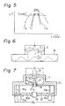
- Figure 5 shows the frequency-voltage characteristics of the conventional device shown in Fig. 1 and of the device shown in Fig. 3.
- the broken curve C0 shows the conventional frequency-voltage characteristic realized by the single cavity resonator shown in Fig. 1
- a solid curve C1 shows a frequency-voltage characteristic realized by the device shown in Fig. 3 when the resonance frequency f01 is equal to the resonance frequency f02 under the condition that the coupling coefficient n2 between the first and the second cavity resonators is made to be relatively small
- a dash-dot curve C2 shows a frequency-voltage characteristic realized by the device shown in Fig.
- the solid curve C1 has a wider flat bandwidth BW1 than the bandwidth of the broken curve C0 when the bandwidth within 0.2 dB of the uppermost output voltage of the curve C1 is compared with that of the curve C0.
- the flat bandwidth, i.e., 0.2 dB-bandwidth, for the cavity resonator coupling type power distributor/power combiner shown in Fig. 3 can be expected to be about twice as wide as that of the conventional single cavity resonator shown in Fig. 1, while the 3-dB bandwidth decreases by a factor 1/ ⁇ 2.
- the resonance frequency f01 is different from the resonance frequency f02 , or when the resonance frequencies f01 and f02 are equal from each other but the coupling coefficient n2 is made greater than that in the case of the curve C1 , the dash-dot curve C2 which is a double-humped resonance curve can be obtained, so that the bandwidth is expanded.
- Figure 6 shows an example of the configuration of the electric field in the device shown in Fig. 3.
- the first cavity resonator 5 is of a cylindrical type and resonates with a TM 0,2,0 mode so as to have an electric field E1.
- the intensity of the electric field E1 at the side wall of the resonator 5 is zero.
- the intensity of the electric field E1 is maximum.
- the intensity of the electric field E1 is local maximum.
- the coupling window 9 is so determined to have a radius equal to 0.694r or 0.604r.
- the diameter of the coupling window 9 is determined to be equal to the distance between two positions where the intensity of the electric field in the first cavity resonator has peak values, the two positions being symmetric with respect to the center of the first cavity resonator.
- the size of the second cavity resonator 6 is so determined that the intensity of the electric field E2 at the side wall of the second cavity resonator 6 is zero. Since the second cavity resonator 6 has the plurality of coupling terminals 8a to 8n, the radius of the second cavity resonator 6 is made larger than the radius of the first cavity resonator 5.
- the coupling coefficient between the first cavity resonator 5 and the second cavity resonator 6 can be made large and without the generation of undesired modes in the first and the second cavity resonators 5 and 6. Therefore, in this coupling, disturbance of the electric field and the generation of higher order modes can be prevented, so that the distribution or combination of microwave electric power can be carried out stably.
- This type of coupling is referred to as mode coupling.
- the mode coupling can be realized not only with the above described TM 0,2,0 mode, but also by any mode type among the TM ⁇ ,r,z modes and the TE ⁇ ,r,z modes.
- FIG. 7 shows a general cross-sectional view of a cavity-resonator coupling type power distributor/power combiner, according to a second embodiment of the present invention.
- a housing 10 made of metal houses a power distributor/power combiner.
- the power distributor/power combiner is constructed of a first cavity resonator 11 and a second cavity resonator 12.
- the first cavity resonator 11 has, at its top surface, a single coupling terminal 13.
- the single coupling terminal 13 is connected to a disk shaped antenna 14 for establishing an electric field coupling between the single coupling terminal 13 and the first cavity resonator 11.
- the second cavity resonator 12 has, at its bottom plate 10b, a plurality of coupling terminals 15a to 15n.
- a plurality of antennas 16a to 16n are respectively connected to the coupling terminals 15a to 15n.
- the antennas 16a to 16n function to establish a magnetic field coupling between the second cavity resonator 12 and the coupling terminals 15a to 15n.
- the electromagnetic coupling between the first cavity resonator 11 and the second cavity resonator 12 is established by a coupling rod 17, instead of the coupling window 9 in the first embodiment.
- the second cavity resonator 12 also has, at the center of the bottom plate 10b, an adjusting screw 19 for controlling the resonance frequency of the second cavity resonator 12.
- the coupling rod 17 is fixed to the bottom metal plate 10a of the first cavity resonator 11 through a dielectric supporting member 18.
- the bottom metal plate 10a also functions as the top surface of the second cavity resonator 12.
- the bottom metal plate or the top surface 10a is part of the metal housing 10.
- the dielectric supporting member 18 has, at its center, a hole for the coupling rod 17.
- the coupling rod 17 has, at both ends, a disk type antenna 17a and a disk type antenna 17b, projecting into the first and the second cavity resonators 11 and 12, for establishing an electric field coupling between the first cavity resonator 11 and the coupling rod 17, and between the coupling rod 17 and the second cavity resonator 12, respectively.
- An adjusting screw 19 for adjusting the resonance frequency of the second cavity resonator 12 is provided at the center of the bottom surface 10b of the housing 10, i.e., at the center of the second cavity resonator 12.
- the height H1 of the first cavity resonator 11 is 8 mm and the diameter D1 is 36 mm.
- the first cavity resonator 11 operates in the TM 0,1,0 mode.
- the height H2 and the diameter D2 of the second cavity resonator 12 are 8 mm and 83 mm, respectively.
- the second cavity resonator 12 operates in the TM 0,2,0 mode.
- the power distributor/power combiner having a construction such as mentioned above can provide a 0.2 dB bandwidth of 600 MHz at 6 GHz, while the conventional single cavity resonator 1 shown in Fig. 1 can provide only a 0.2 dB bandwidth of 300 MHz.
- the 0.2 dB bandwidth is about twice that of the conventional device.
- the hole for penetrating the rod 17 can be made very small in comparison with the window 9 in the first embodiment in Fig. 3. Therefore, the electric field is not disturbed due to the window 9, and the coupling between the first and the second cavity resonators 11 and 12 can be made much stronger than in the first embodiment.
- the coupling coefficient between the first and the second cavity resonators 11 and 12 is determined by the size and the position of the antennas 17a and 17b of the coupling rod 17.
- rod antennas may also be possible.
- FIG. 8 the difficulty of adjusting the coupling coefficient is substantially removed.
- Reference numeral 20 designates a coupling window, 21 an adjusting screw for adjusting the resonance frequency of the second cavity resonator 12, and 22 an adjusting antenna for adjusting the coupling coefficient between the first cavity resonator 11 and the second cavity resonator 12, respectively.
- the bottom plate 10b of the housing 10 has, at its center, a tapped hole 23.
- the adjusting screw 21 is screwed and fixed through the tapped hole 23 to the bottom plate 10b.
- the resonance frequency can be controlled by the height h of the adjusting screw 21 projecting inside the second cavity resonator 12.
- the adjusting screw 21 has, at its center, a tapped hole 24 through which the antenna 22 is screwed and fixed.
- the coupling coefficient of the first cavity resonator 11 with the second cavity resonator 12 is determined by adjusting the position of the antenna 22 with respect to the coupling window 20 by screwing the antenna 22 in the tapped hole 24.
- FIG. 9 A more detailed structure of the adjusting screw 21 and the adjusting antenna 22 is shown in Fig. 9.
- reference numerals 27 and 28 represent locking nuts for tightly fixing the adjusting screw 21 to the bottom plate 10b, and the antenna 22 to the adjusting screw 21, respectively.
- the adjusting mechanism of the adjusting screw 21 and the antenna 22 is not restricted to the third embodiment shown in Figs. 8 and 9.
- Various constructions may be employed according to the present invention.
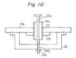
- a supporting member 25 may be fixed under the bottom plate 10b, as shown in Fig. 10.
- Fig. 10 a partial cross-sectional view of a power distributor/power combiner according to the fourth embodiment of the present invention is illustrated.
- the bottom plate 10b of the housing 10 also has, at its center, the tapped hole 23.
- An adjusting screw 21a is screwed and held in the tapped hole 23 to the bottom plate 10b.
- the adjusting screw 21a does not have a tapped hole as in the embodiment in Fig.
- the supporting member 25 has, at its center, a tapped hole 24a.
- An antenna 22a passes through a hole in the center of the adjusting screw 21a and is screwed into and fixed by the tapped hole 24a in the supporting member 25.
- the height of the adjusting screw 21a and the position of the antenna 22a can be adjusted independently.
- Reference symbols 27a and 28a represent locking nuts for tightly fixing the adjusting screw 21a and the antenna 22a to the bottom plate 10b and the supporting member 25, respectively.
- the coupling between the first cavity resonator and the single coupling terminal, and the coupling between the second cavity resonator and the plurality of coupling terminals are described as electric field coupling and magnetic field coupling, respectively.
- the present invention is not restricted to the above-mentioned coupling. Any type of electromagnetic coupling may be possible without disturbing the electromagnetic field in the cavity resonators.
- the bandwidth of the power distributer/power combiner can be made wide in comparison with the conventional type. Also, a number of coupling terminals can be easily provided in the second cavity resonator. Further, by making the size of the coupling window equal to the distance between the peak values of the electric field in the cavity resonators, mode coupling can be realised without generating undesired modes, and therefore, power distribution or power combination can be carried out stably. Still further, by providing an adjusting screw and an antenna having a screw, adjustment of the resonance frequency and the coupling coefficient can be easily carried out.
Landscapes
- Control Of Motors That Do Not Use Commutators (AREA)
Claims (11)
- Eine Hohlraumresonatorapparatur mit:
einer ersten Hohlraumresonatorvorrichtung (5,11), die einen einzigen Koppelanschluß (7,13) besitzt, der Eingangs/Ausgangssignale koppelt;
einer Vielzahl von Koppelanschlüssen (8,15);
und Koppelvorrichtungen(9,17,20) zur elektromagnetischen Kopplung mit der ersterer Hohlraumresonatorvorrichtung (5,11), dadurch gekennzeichnet, daß:
die Apparatur ist ein Leistungsverteiler/Leistungsvereiniger vom Hohlraumresonator-Koppeltyp, der wahlweise als Verteiler- und als Verbindungseinheit in Verbindung mit Vielfachverstärkern funktioniert, wobei besagter Leistungs-verteiler und -vereiniger ferner umfaßt:
eine zweite, zylinderförmige Hohlraumresonatorvorrichtung (6,12), die mit der Vielzahl von Koppelanschlüssen (8,15) ausgestattet ist, um eine Vielzahl von Ausgangs/Eingangssignalen zu koppeln, und mit besagten Vielfachverstärkern verbunden ist und die mit einer TM0, m ,0-Mode schwingt, wobei m eine ganze positive Zahl ist;
Koppelvorrichtungen (9,17,20), die für die elektromagnetische Kopplung der zweiten Hohlraumresonatorvorrichtung (6,12) mit der ersten Hohlraumresonatorvorrichtung (5,11) vorgesehen sind. - Eine Hohlraumresonatorapparatur nach Anspruch 1, in der die erste zylinderförmige Hohlraumresonatorvorrichtung (5,11) in der TM0, n ,0-Mode schwingt, wobei n eine positive ganze Zahl ist, die gleich oder kleiner als m ist.
- Eine Hohlraumresonatorapparatur nach Anspruch 1 oder 2, in der ein Metallgehäuse (10) die erste (11) und die zweite (12) Hohlraumresonatorvorrichtung bildet und
in der die Koppelvorrichtungen enthalten:
eine Metallplatte (10a), die zwischen der ersten Hohlraumresonatorvorrichtung (11) und der zweiten Hohlraumresonatorvorrichtung (12) angebracht ist und diese trennt, wobei die Metallplatte ein integraler Bestandteil ist des Metallgehäuses (10) des Hohlraumresonatorkoppeltyps, der die Leistung verteilt/vereinigt und ein Zentrum besitzt;
ein dielektrisches Aufnahmeelement (18), das durch die Mitte der Metallplatte (10a) geht und ein Zentrum besitzt; und
einen Koppelstab (17), der durch das Zentrum des dielektrischen Aufnahmeelementes geht und der Antennen (17a,17b) an jedem Ende des Koppelstiftes besitzt, um die elektrische Feldkopplung herzustellen, zwischen der ersten Hohlraumresonatorvorrichtung (11) und dem Koppelstift (17) einerseits und der zweiten Hohlraumresonatorvorrichtung (12) und den Koppelstift andererseits. - Eine Hohlraumresonatorapparatur nach Anspruch 1 oder 2, in der die Koppelmittel ein Koppelfenster (9,20) enthalten, das die erste Hohlraumresonatorvorrichtung (5,11) mit der zweiten Hohlraumresonatorvorrichtung (6,12) verkoppelt.
- Eine Hohlraumresonatorapparatur nach einem der vorangegangenen Ansprüche , wobei der einzelne Koppelanschluß (7,13) der ersten Hohlraumresonatorvorrichtung (5,11) eine Antenne (71,14) innerhalb erster Hohlraumresonatorvorrichtung enthalt, um die Kopplung des elektrischen Feldes herzustellen.
- Ein Leistungsverteiler/Leistungsvereiniger vom Hoblraumresonator-Koppeltyp nach einem der vorangegangenen Ansprüche, wobei jeder der Vielzahl von Koppelanschlüssen (8) der zweiten Hohlraumresonatorvorrichtung eine magnetische Feld-Koppelschleife (81) enthält.
- Eine Hohlraumresonatorapparatur nach Anspruch 1 oder 2, bei der besagtes Koppelmittel eine Metallplatte (10a) enthält, die eine Bodenmetallplatte der ersten Hohlraumresonatorvorrichtung (11) und eine obere Oberfläche der zweiten Hohlraumresonatorvorrichtung (12) bildet und die ein Koppelfenster (20) besitzt, das die erste Hohlraumresonatorvorrichtung mit der zweiten Hohlraumresonatorvorrichtung verkoppelt.
- Eine Hohlraumresonatorapparatur nach Anspruch 4 oder 7, in der die positive ganze Zahl n den Wert eins übertrifft und der Durchmesser des Koppelfensters (9,20) gleich ist mit dem Abstand zwischen zwei Stellungen, in denen die Intensität des elektrischen Feldes in der ersten Hohlraumresonatorvorrichtung (5,11) einen Spitzenwert annimmt, und die zwei Stellungen symmetrisch bezüglich dem Zentrum des ersten Hohlraumresonators sind, wodurch eine Modenkopplung ohne Erzeugung unerwünschter Moden erreicht wird zwischen der ersten Hohlraumresonatorvorrichtung (5,11) und der zweiten Hohlraumresonatorvorrichtung (6,12).
- Eine Hohlraumresonatorapparatur nach Anspruch 4, 7 oder 8, die weiter enthält: eine Stellschraube (21,21a), die die Resonanzfrequenz der zweiten Hohlraumresonatorvorrichtung (12) kontrolliert, und eine justierbare Antenne (22,22a), die den Koppelkoeffizienten zwischen der ersten Hohlraumresonatorvorrichtung (11) und der zweiten Hohlraumresonatorvorrichtung (12) kontrolliert, indem die Lage der justierbaren Antenne bezüglich der Lage des Koppelfensters (20) eingestellt wird, wobei die zweite Hohlraumresonatorvorrichtung (12) eine Grundplatte (10b) gegenüber dem Koppelfenster (20), die Stellschraube und die justierbare Antenne, die auf der Grundplatte (10b) befestigt sind, umfaßt.
- Eine Hohlraumresonatorapparatur nach Anspruch 9, in der der Boden (10b) der zweiten Hohlraumresonatorvorrichtung eine Gewindeöffnung (23) zur Aufnahme der Stellschraube (21) besitzt und die Stellschraube eine zweite Gewindeöffnung (24) zur Aufnahme der justierbaren Antenne (22) besitzt.
- eine Hohlraumresonatorapparatur nach Anspruch 9, bei der die Bodenplatte (10b) der zweiten Hohlraumresonatorvorrichtung eine erste Gewindeöffnung zur Aufnahme und Halterung der Stellschraube (21a) besitzt, die Stellschraube eine Öffnung (23) zur Aufnahme der justierbaren Antenne besitzt und eine Aufnahmevorrichtung (25) auf der Grundplatte (10b) befestigt und die Aufnahmevorrichtung (25) eine zweite Gewindeöffnung (24a) zur Aufnahme und Halterung der justierbaren Antenne besitzt.
Applications Claiming Priority (4)
| Application Number | Priority Date | Filing Date | Title |
|---|---|---|---|
| JP11064/83 | 1983-01-26 | ||
| JP1106483A JPS59139703A (ja) | 1983-01-26 | 1983-01-26 | 空胴共振器結合型電力分配合成器 |
| JP1106383A JPS59139702A (ja) | 1983-01-26 | 1983-01-26 | 空胴共振器結合型電力分配合成器 |
| JP11063/83 | 1983-01-26 |
Publications (3)
| Publication Number | Publication Date |
|---|---|
| EP0121294A2 EP0121294A2 (de) | 1984-10-10 |
| EP0121294A3 EP0121294A3 (en) | 1986-03-19 |
| EP0121294B1 true EP0121294B1 (de) | 1991-11-13 |
Family
ID=26346435
Family Applications (1)
| Application Number | Title | Priority Date | Filing Date |
|---|---|---|---|
| EP84300428A Expired EP0121294B1 (de) | 1983-01-26 | 1984-01-25 | Leistungsverteilungs- oder Kombinierungsgerät vom Typ gekoppelter Hohlraumresonatoren |
Country Status (4)
| Country | Link |
|---|---|
| US (1) | US4686494A (de) |
| EP (1) | EP0121294B1 (de) |
| CA (1) | CA1216907A (de) |
| DE (1) | DE3485253D1 (de) |
Cited By (1)
| Publication number | Priority date | Publication date | Assignee | Title |
|---|---|---|---|---|
| CN107194159A (zh) * | 2017-05-04 | 2017-09-22 | 电子科技大学 | 外部激励下带孔阵腔体电磁谐振的解析方法 |
Families Citing this family (13)
| Publication number | Priority date | Publication date | Assignee | Title |
|---|---|---|---|---|
| FR2599554A1 (fr) * | 1986-05-30 | 1987-12-04 | Thomson Csf | Klystron a faisceaux multiples fonctionnant au mode tm02 |
| US5239272A (en) * | 1990-03-09 | 1993-08-24 | Eev Limited | Electron beam tube arrangements having primary and secondary output cavities |
| US5376901A (en) * | 1993-05-28 | 1994-12-27 | Trw Inc. | Hermetically sealed millimeter waveguide launch transition feedthrough |
| AU6038396A (en) * | 1995-06-07 | 1996-12-30 | E-Systems Incorporated | Microwave packaging technique for integration of microwave f ilters and microwave cavity structures into microwave housin gs |
| DE19608001C2 (de) * | 1996-03-04 | 2000-07-06 | Poly Clip System Gmbh & Co Kg | Verfahren und Vorrichtung zum Herstellen verpackter Lebensmittel mit Rauchgeschmack |
| US5739690A (en) * | 1996-04-04 | 1998-04-14 | Colorado Seminary | Crossed-loop resonator structure for spectroscopy |
| US5942944A (en) * | 1998-01-12 | 1999-08-24 | The United States Of America As Represented By The Secretary Of The Army | Low loss based power divider/combiner for millimeter wave circuits |
| US6466111B1 (en) | 1999-12-06 | 2002-10-15 | Kathrein Inc., Scala Division | Coupler for resonant cavity |
| US6404307B1 (en) | 1999-12-06 | 2002-06-11 | Kathrein, Inc., Scala Division | Resonant cavity coupling mechanism |
| US6724261B2 (en) * | 2000-12-13 | 2004-04-20 | Aria Microwave Systems, Inc. | Active radio frequency cavity amplifier |
| JP3625197B2 (ja) * | 2001-01-18 | 2005-03-02 | 東京エレクトロン株式会社 | プラズマ装置およびプラズマ生成方法 |
| JP5806098B2 (ja) * | 2010-12-20 | 2015-11-10 | 日本電信電話株式会社 | フィンライン型偏波分離器 |
| US9196944B2 (en) * | 2012-08-06 | 2015-11-24 | Teledyne Wireless, Llc | Apparatus for combining high frequency electrical energy from a plurality of sources |
Family Cites Families (12)
| Publication number | Priority date | Publication date | Assignee | Title |
|---|---|---|---|---|
| FR2038491A5 (de) * | 1969-03-17 | 1971-01-08 | Radiotechnique Compelec | |
| US2496772A (en) * | 1944-07-12 | 1950-02-07 | Philco Corp | Cavity resonator |
| US2796587A (en) * | 1956-04-20 | 1957-06-18 | Collins Radio Co | U. h. f. impedance matching means |
| DE1223966B (de) * | 1959-09-30 | 1966-09-01 | Siemens Ag | Hohlleiterbandfilter |
| US3156879A (en) * | 1960-07-06 | 1964-11-10 | Gen Electric | Power divider utilizing inductive coupling in a cavity resonator excited in the tm m ode |
| US3308402A (en) * | 1964-12-30 | 1967-03-07 | Teledyne Inc | Cavity resonator apparatus |
| DE2032597A1 (de) * | 1969-07-05 | 1971-01-07 | Tavkozlesi Kutato Intezet, Budapest | Mikrowellen-Filterweichensystem |
| US4143334A (en) * | 1978-03-16 | 1979-03-06 | Motorola Inc. | Microwave/millimeter wave oscillator |
| US4147994A (en) * | 1978-07-31 | 1979-04-03 | Raytheon Company | Power combiner |
| IT1202869B (it) * | 1979-01-24 | 1989-02-15 | Sits Soc It Telecom Siemens | Klystron oscillatore a due cavita' |
| US4291288A (en) * | 1979-12-10 | 1981-09-22 | Hughes Aircraft Company | Folded end-coupled general response filter |
| DE3108758A1 (de) * | 1981-03-07 | 1982-09-16 | Licentia Patent-Verwaltungs-Gmbh, 6000 Frankfurt | Mikrowellen-empfangseinrichtung |
-
1984
- 1984-01-17 CA CA000445431A patent/CA1216907A/en not_active Expired
- 1984-01-18 US US06/571,811 patent/US4686494A/en not_active Expired - Lifetime
- 1984-01-25 DE DE8484300428T patent/DE3485253D1/de not_active Expired - Lifetime
- 1984-01-25 EP EP84300428A patent/EP0121294B1/de not_active Expired
Cited By (2)
| Publication number | Priority date | Publication date | Assignee | Title |
|---|---|---|---|---|
| CN107194159A (zh) * | 2017-05-04 | 2017-09-22 | 电子科技大学 | 外部激励下带孔阵腔体电磁谐振的解析方法 |
| CN107194159B (zh) * | 2017-05-04 | 2020-09-15 | 电子科技大学 | 外部激励下带孔阵腔体电磁谐振的解析方法 |
Also Published As
| Publication number | Publication date |
|---|---|
| DE3485253D1 (de) | 1991-12-19 |
| CA1216907A (en) | 1987-01-20 |
| US4686494A (en) | 1987-08-11 |
| EP0121294A2 (de) | 1984-10-10 |
| EP0121294A3 (en) | 1986-03-19 |
Similar Documents
| Publication | Publication Date | Title |
|---|---|---|
| EP0877435B1 (de) | Dielektrischer Resonator, dielektrisches Bandsperrfilter und dielektrisches Filter | |
| US4686494A (en) | Cavity resonator coupling type power distributor/power combiner comprising coupled input and output cavity resonators | |
| AU687240B2 (en) | Method for tuning a summing network of a base station, and a bandpass filter | |
| US7310031B2 (en) | Dielectric resonators and circuits made therefrom | |
| US7187337B2 (en) | Planar antenna with slot line | |
| US5995047A (en) | Microstrip antenna device, in particular for telephone transmissions by satellite | |
| EP0122084B1 (de) | Holhraumresonatorvorrichtung zur Leistungsverteilung und -zuschaltung | |
| EP0423114B1 (de) | Mikrowellenmultiplexer mit mehrmodenfilter | |
| US7183881B2 (en) | Cross-coupled dielectric resonator circuit | |
| US4498061A (en) | Microwave receiving device | |
| EP0123448B1 (de) | Oszillator mit frequenzbestimmendem Zweimoden-Hohlraumresonator | |
| EP0657954B1 (de) | Verbessertes dielektrisches Filter mit mehreren Resonatoren | |
| US20050190110A1 (en) | Antenna structure and television receiver | |
| US4636756A (en) | Apparatus for varying the magnetic field for a magnetic resonance element | |
| US7956706B2 (en) | Multiband filter having comb-line and ceramic resonators with different pass-bands propagating in different modes | |
| US5349316A (en) | Dual bandpass microwave filter | |
| US4871983A (en) | Electronically tuned dielectric resonator stabilized oscillator | |
| US4077039A (en) | Launching and/or receiving network for an antenna feedhorn | |
| US4590479A (en) | Broadcast antenna system with high power aural/visual self-diplexing capability | |
| JPH0374909A (ja) | 電子制御アンテナ装置 | |
| JP3760051B2 (ja) | Nrdガイドミリ波帯発振器の周波数調整装置 | |
| US4083016A (en) | Coupled-cavity microwave oscillator | |
| KR100204439B1 (ko) | 유전체 공진기 필터 | |
| US20030107458A1 (en) | Method and apparatus for creating a radio frequency filter | |
| US4143334A (en) | Microwave/millimeter wave oscillator |
Legal Events
| Date | Code | Title | Description |
|---|---|---|---|
| PUAI | Public reference made under article 153(3) epc to a published international application that has entered the european phase |
Free format text: ORIGINAL CODE: 0009012 |
|
| AK | Designated contracting states |
Designated state(s): DE FR GB IT NL |
|
| PUAL | Search report despatched |
Free format text: ORIGINAL CODE: 0009013 |
|
| AK | Designated contracting states |
Kind code of ref document: A3 Designated state(s): DE FR GB IT NL |
|
| 17P | Request for examination filed |
Effective date: 19860605 |
|
| 17Q | First examination report despatched |
Effective date: 19880902 |
|
| ITF | It: translation for a ep patent filed | ||
| GRAA | (expected) grant |
Free format text: ORIGINAL CODE: 0009210 |
|
| AK | Designated contracting states |
Kind code of ref document: B1 Designated state(s): DE FR GB IT NL |
|
| REF | Corresponds to: |
Ref document number: 3485253 Country of ref document: DE Date of ref document: 19911219 |
|
| ET | Fr: translation filed | ||
| PLBE | No opposition filed within time limit |
Free format text: ORIGINAL CODE: 0009261 |
|
| STAA | Information on the status of an ep patent application or granted ep patent |
Free format text: STATUS: NO OPPOSITION FILED WITHIN TIME LIMIT |
|
| PGFP | Annual fee paid to national office [announced via postgrant information from national office to epo] |
Ref country code: GB Payment date: 19921106 Year of fee payment: 10 |
|
| 26N | No opposition filed | ||
| PGFP | Annual fee paid to national office [announced via postgrant information from national office to epo] |
Ref country code: FR Payment date: 19921222 Year of fee payment: 10 |
|
| PGFP | Annual fee paid to national office [announced via postgrant information from national office to epo] |
Ref country code: NL Payment date: 19930131 Year of fee payment: 10 |
|
| PGFP | Annual fee paid to national office [announced via postgrant information from national office to epo] |
Ref country code: DE Payment date: 19930323 Year of fee payment: 10 |
|
| PG25 | Lapsed in a contracting state [announced via postgrant information from national office to epo] |
Ref country code: GB Effective date: 19940125 |
|
| PG25 | Lapsed in a contracting state [announced via postgrant information from national office to epo] |
Ref country code: NL Effective date: 19940801 |
|
| NLV4 | Nl: lapsed or anulled due to non-payment of the annual fee | ||
| GBPC | Gb: european patent ceased through non-payment of renewal fee |
Effective date: 19940125 |
|
| PG25 | Lapsed in a contracting state [announced via postgrant information from national office to epo] |
Ref country code: FR Effective date: 19940930 |
|
| PG25 | Lapsed in a contracting state [announced via postgrant information from national office to epo] |
Ref country code: DE Effective date: 19941001 |
|
| REG | Reference to a national code |
Ref country code: FR Ref legal event code: ST |