EP0121273A2 - Verfahren und Vorrichtung zur Atomspektroskopie - Google Patents
Verfahren und Vorrichtung zur Atomspektroskopie Download PDFInfo
- Publication number
- EP0121273A2 EP0121273A2 EP84200291A EP84200291A EP0121273A2 EP 0121273 A2 EP0121273 A2 EP 0121273A2 EP 84200291 A EP84200291 A EP 84200291A EP 84200291 A EP84200291 A EP 84200291A EP 0121273 A2 EP0121273 A2 EP 0121273A2
- Authority
- EP
- European Patent Office
- Prior art keywords
- probe
- sample
- cuvette
- temperature
- tubular body
- Prior art date
- Legal status (The legal status is an assumption and is not a legal conclusion. Google has not performed a legal analysis and makes no representation as to the accuracy of the status listed.)
- Granted
Links
- 238000000559 atomic spectroscopy Methods 0.000 title claims abstract description 6
- 239000000523 sample Substances 0.000 claims abstract description 153
- 238000000889 atomisation Methods 0.000 claims abstract description 20
- 238000000034 method Methods 0.000 claims abstract description 16
- 238000010438 heat treatment Methods 0.000 claims abstract description 14
- 239000007788 liquid Substances 0.000 claims abstract description 11
- 238000000151 deposition Methods 0.000 claims abstract description 10
- OKTJSMMVPCPJKN-UHFFFAOYSA-N Carbon Chemical compound [C] OKTJSMMVPCPJKN-UHFFFAOYSA-N 0.000 claims description 17
- 229910002804 graphite Inorganic materials 0.000 claims description 15
- 239000010439 graphite Substances 0.000 claims description 15
- 238000001035 drying Methods 0.000 claims description 14
- 238000004380 ashing Methods 0.000 claims description 7
- 239000004020 conductor Substances 0.000 claims description 3
- 239000007787 solid Substances 0.000 abstract description 6
- 238000010521 absorption reaction Methods 0.000 description 4
- 230000008021 deposition Effects 0.000 description 3
- 239000010453 quartz Substances 0.000 description 3
- 230000005855 radiation Effects 0.000 description 3
- VYPSYNLAJGMNEJ-UHFFFAOYSA-N silicon dioxide Inorganic materials O=[Si]=O VYPSYNLAJGMNEJ-UHFFFAOYSA-N 0.000 description 3
- LGDAGYXJBDILKZ-UHFFFAOYSA-N [2-methyl-1,1-dioxo-3-(pyridin-2-ylcarbamoyl)-1$l^{6},2-benzothiazin-4-yl] 2,2-dimethylpropanoate Chemical compound CC(C)(C)C(=O)OC=1C2=CC=CC=C2S(=O)(=O)N(C)C=1C(=O)NC1=CC=CC=N1 LGDAGYXJBDILKZ-UHFFFAOYSA-N 0.000 description 2
- 238000001479 atomic absorption spectroscopy Methods 0.000 description 2
- 238000001636 atomic emission spectroscopy Methods 0.000 description 2
- 238000001391 atomic fluorescence spectroscopy Methods 0.000 description 2
- 229910052799 carbon Inorganic materials 0.000 description 2
- 239000007789 gas Substances 0.000 description 2
- 238000003780 insertion Methods 0.000 description 2
- 230000037431 insertion Effects 0.000 description 2
- 239000000463 material Substances 0.000 description 2
- 238000012986 modification Methods 0.000 description 2
- 230000004048 modification Effects 0.000 description 2
- 230000001681 protective effect Effects 0.000 description 2
- 239000002904 solvent Substances 0.000 description 2
- 230000015572 biosynthetic process Effects 0.000 description 1
- 239000008280 blood Substances 0.000 description 1
- 210000004369 blood Anatomy 0.000 description 1
- 210000001124 body fluid Anatomy 0.000 description 1
- 239000010839 body fluid Substances 0.000 description 1
- 238000010276 construction Methods 0.000 description 1
- 238000004993 emission spectroscopy Methods 0.000 description 1
- 238000005286 illumination Methods 0.000 description 1
- 239000011261 inert gas Substances 0.000 description 1
- 238000005259 measurement Methods 0.000 description 1
- 230000003647 oxidation Effects 0.000 description 1
- 238000007254 oxidation reaction Methods 0.000 description 1
- 238000005070 sampling Methods 0.000 description 1
- 238000004544 sputter deposition Methods 0.000 description 1
- WFKWXMTUELFFGS-UHFFFAOYSA-N tungsten Chemical compound [W] WFKWXMTUELFFGS-UHFFFAOYSA-N 0.000 description 1
- 229910052721 tungsten Inorganic materials 0.000 description 1
- 239000010937 tungsten Substances 0.000 description 1
Images

Classifications
-
- G—PHYSICS
- G01—MEASURING; TESTING
- G01N—INVESTIGATING OR ANALYSING MATERIALS BY DETERMINING THEIR CHEMICAL OR PHYSICAL PROPERTIES
- G01N21/00—Investigating or analysing materials by the use of optical means, i.e. using sub-millimetre waves, infrared, visible or ultraviolet light
- G01N21/62—Systems in which the material investigated is excited whereby it emits light or causes a change in wavelength of the incident light
- G01N21/71—Systems in which the material investigated is excited whereby it emits light or causes a change in wavelength of the incident light thermally excited
- G01N21/74—Systems in which the material investigated is excited whereby it emits light or causes a change in wavelength of the incident light thermally excited using flameless atomising, e.g. graphite furnaces
Definitions
- the invention relates to a method of atomising a sample for atomic spectroscopy and to an spectrophotometer comprising an electrothermal atomiser in the form of a tubular body of electrically conductive material, means for depositing a sample on a probe, means for inserting the probe into the tubular body and means for passing an electrical current through the tubular body to heat the interior of the tubular body to a temperature which is sufficient to atomise the sample.
- a sample is introduced into a graphite tube atomiser by means of a sample carrier in the form of a wire helix of temperature resistant, electrically conducting material, such as tungsten.
- the sample carrier is provided with electrical connections whereby it can be heated in a controlled manner by passing an electric current therethrough.
- the sample carrier itself acts as a resistor in combination with the electrical connections and the power source thus constituting a heating device.
- U.K. Patent Application No. 2088582A discloses sample introduction apparatus comprising a sample carrier for insertion into the graphite tube and shaped to accept non-gaseous sample material and means external of the graphite tube for radiantly heating the carrier. This enables the handling of relatively large solid or liquid sample quantities, including powdery material without the disadvantages referred to above.
- the invention provides a method of. atomising a sample for atomic spectroscopy comprising the steps of inserting a probe into a cuvette, depositing the sample to be atomised onto the probe, withdrawing the probe from the cuvette, heating the cuvette to a desired temperature sufficient to atomise the sample and inserting the probe into the cuvette.
- This method gives the advantage that since the sample is deposited on the probe within the cuvette a standard autosampler which has been designed to deposit the sample into the cuvette can be used.
- the method may include the step of drying the deposited sample by heating the cuvette to a desired temperature below the atomisation temperature before withdrawing the probe from the cuvette.
- This has the further advantage of enabling the second heat source to be dispensed with. It is normal to provide a control means for raising the temperature of the cuvette to the atomisation temperature, which differs for different elements, and to monitor the temperature of the cuvette.
- This control means which is already present can be used to regulate the drying process as is conventional when the sample is deposited directly on the surface of the cuvette.
- the method may include the step of raising the temperature of the cuvette to a second higher temperature to ash the sample after the sample has been dried, the second temperature being below the atomisation temperature. This step is necessary when samples which form a carbonaceous mass on drying, such as blood, are to be analysed.
- the second temperature and the time during which it is held are again determined empirically as is the case when the samples are deposited directly on the surface of the cuvette.
- the invention further provides a spectrophotometer as described in the opening paragraph characterised in that the'means for depositing the sample on the probe is arranged to deposit the sample on the probe when the probe is within the tubular body and that means are provided for withdrawing the probe from the tubular body before the temperature of the interior of the body is raised to the atomisation temperature and for re-inserting the probe and sample into the tubular body after its interior temperature has reached the atomisation temperature.
- This apparatus has the advantage that an autosampler can be used to deposit the sample either directly onto the surface of the tubular body or cuvette or onto the probe without requiring any modification.
- a standard atomiser can be converted to a probe atomiser merely by providing an access aperture for the probe into the cuvette and the probe and actuator assembly.
- Means may be provided for drying a liquid sample deposited on the probe before withdrawing the probe from the tubular body, the drying means comprising means for raising the temperature of the tubular body to a desired temperature below the atomisation temperature.
- ashing means comprising means for raising the temperature of the tubular body to a second higher desired temperature, which second temperature is below the atomisation temperature.
- the controller is provided with means for selecting the temperature and the time for which the temperature is held, these means normally being a keyboard, and a control loop which senses the actual temperature of the tubular body and regulates the voltage applied to produce the desired temperature. Alternatively the applied voltage may be selected and held at a constant value.
- the means for withdrawing the probe from and inserting the probe in the tubular body may comprise a solenoid. This provides a convenient and inexpensive means for moving the probe from a first position within the tubular body to a second position remote from the tubular body.
- the tubular body may be constructed totally of pyrolytic graphite.
- the probe may also be constructed totally of pyrolytic graphite.
- pyrolytic graphite for the tubular body gives the advantage of long life and reduced permeation of the sample into the wall of the tubular body. If other forms of carbon are used for the tubular body the life of the tubular body is significantly reduced as the region around the slot for the introduction of the probe and between the slot and the sample insertion aperture disintegrates after comparatively few atomisation cycles.
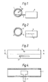
- Figures 1 and 2 show a graphite cuvette 1, a graphite prcbe 2 and a probe actuator 3.
- the cuvette 1 is in the form of a hollow cylinder and is provided with a circular aperture 4 and a longitudinally extending slot 5.
- the probe actuator 3, which may conveniently be a solenoid, is arranged to be capable of moving the probe 3 between a first position within the cuvette, as shown in Figure 1, and a second position outside the cuvette, as shown in Figure 2.
- a sample dispenser 6 may be introduced into the cuvette 1 through the aperture 4 to enable a sample to be deposited on the probe 2 within the cuvette 1.
- the sample dispenser 6 may be a pipette manually introduced by an analyst or may be the dosing tube of an autosampler, for example the autosampler described in U.K. Patent Application No. 2049179A, the contents of which are incorporated by reference herein.
- Figure 4 is a cross sectional view on line A-A of Figure 3 and shows the probe 2 in position within the cuvette 1.
- the probe 2 is introduced into the cuvette 1 by the actuator 3 and a sample is deposited on the probe 2 through the sample dispenser 6.
- the sample dispenser 6 is then withdrawn from the cuvette 1 and an electric current is passed through the cuvette 1, the current heating the cuvette to a desired temperature which is below the atomisation temperature but which is sufficient to evaporate the sample solvent.
- the actuator then withdraws the probe 2 from the cuvette to the second position as shown in Figure 2.
- the cuvette 1 is then heated to a temperature sufficient to atomise the sample to be atomised by passing a greater electric current through it and when the cuvette 1 has reached the atomising temperature the actuator 3 moves the probe 2 into the first position as shown in Figure 1 so that the sample on the probe is atomised by heat radiated from the walls of the cuvette.
- This method of atomisation has a number of advantages. Since the cuvette 1 is at a steady temperature before the sample is inserted the possibility of the sample being atomised by the hotter central portion of the cuvette, condensing on the cooler end portions and then being re-atomised as the whole cuvette heats up is reduced; the speed of atomisation may be increased due to the lower thermal mass of the probe; by sampling onto the probe within the cuvette a standard autosampler can be used; and by using the cuvette to evaporate the sample solvent a second heat source is rendered unnecessary.
- a carbonaceous mass may be formed on the probe after the drying step.
- the temperature of the cuvette 1 is further increased to ash the sample before the probe is withdrawn from the cuvette.
- This second ashing temperature is, of course, below that required to atomise the sample.
- the probe may be withdrawn from the cuvette before any current is applied to the cuvette and only re-inserted when the cuvette has reached the atomisation temperature.
- drying of solid samples is not necessary it may be necessary to ash some solid samples in which case the temperature of the cuvette 1 is raised to the ashing temperature before the probe is withdrawn from the cuvette.
- the described method of atomising the sample may be used in atomic absorption, atomic emission, and atomic fluorescence spectroscopy.
- the form of the cuvette 1 may need to be modified to enable the particular technique to be used.
- the cuvette shown in Figures 1 to 4 is suitable for atomic absorption or emission spectroscopy but for atomic fluorescence measurements a viewing path transverse to the illumination path, which is along the axis of the tube, must be provided. Such arrangements would be readily apparent to the worker skilled in the art.
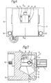
- FIGs 5,6 and 7 show the cuvette 1, probe 2, and actuator 3 mounted in and on a furnace for an atomic absorption spectrophotometer.
- the furnace comprises a body 10 having a hinged door 11.
- two contact jaws, one of which is shown at 12 grip each end of the cuvette 1.
- the jaws have electrical connection terminals, oner of which is shown at 13, to which an electrical current source may be connected for passing a current through the cuvette.
- the contact jaw 12 comprises a fixed lower portion 14 and a pivotted upper portion 15 which can be pivotted by moving a member, 16 into the body 10,horizontally to the left in the embodiment shown in Figure 7.
- the actuator 3 which is in the form of a solenoid is attached to the door 11 of the furnace by four screws 17 to 20 and the probe 2 passes through an aperture 21 in the door 11.
- a further aperture 22 is provided in the front of the door 11 through which the dosing tube 6 may be inserted to deposite a sample on the probe.
- the aperture 22 is closed when the cuvette is being heated so that the escape of protective gas is reduced. Since the cuvette 1 is normally made of carbon it is necessary to prevent rapid oxidation when it is heated to the atomising temperatures which may be in the region of 3000°C. Consequently it is customary to provide a flow of inert gas over and through the cuvette 1.
- the door 11 is hinged along its bottom edge, being mounted between two fixed members 23 and 24 by a shaft 25 the ends of which are free to rotate in the fixed members 23 and 24.
- the opening and closing of the door 11 is performed by a rod 26 pivotally connected to a lug 27 on the door 11 and operated by a piston 28 in a cylinder.
- a quartz window 29 is set in both sides of the door 11, the quartz windows being aligned with the longitudinal axis of the tubular body 1.
- the door 11 is normally kept closed and only opened to replace the cuvette when it has reached the end of its life.
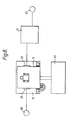
- Figure 8 shows an atomic absorption spectrophotometer which comprises a radiation source 80, which may be for example a hollow cathode lamp, whose radiation is arranged to pass through the cuvette 1 within the furnace body 10 via the quartz windows 29. The radiation then passes through a monochromator 81 and falls on a detector 82.
- a control unit 83 is connected to the furnace to provide the appropriate voltages at and for the appropriate times for the cuvette and also control signals for the solenoid actuator and for the flow of protective gas over the cuvette.
- controllers are well known in the art for providing the currents for drying, ashing and atomising the samples, one arrangement being that described in German Patent No. 2008295.
- the operation of the solenoid merely requires a signal which causes the probe to be withdrawn when the atomisation current is fed to the cuvette.
- the controller 83 may comprise the unit sold by Pye Unicam Limited as the PU9095 Video Furnace modified to give a further output to control the solenoid actuator.
- the spectrophotometer shown in Figure 8 may be a currently manufactured instrument such as the Pye Unicam SP9 or PU9000 series with the furnace door assembly modified to provide the facilities shown in and described with reference to Figures 5 to 7 together with the probe and actuator assembly and a cuvette having a probe entry slot.
- the cuvettes may be made from any suitable material
- the furnace may be of different construction
- the form of the cuvette may be modified to be suitable for use in atomic emission or atomic fluorescence spectroscopy
- the probe actuator may comprise a motor and cam arrangement or an arrangement similar to that shown in U.K. Patent Application no. 2088582A.
Landscapes
- Health & Medical Sciences (AREA)
- Life Sciences & Earth Sciences (AREA)
- Analytical Chemistry (AREA)
- Biochemistry (AREA)
- General Life Sciences & Earth Sciences (AREA)
- Nuclear Medicine, Radiotherapy & Molecular Imaging (AREA)
- Physics & Mathematics (AREA)
- Chemical & Material Sciences (AREA)
- Environmental & Geological Engineering (AREA)
- Geology (AREA)
- General Health & Medical Sciences (AREA)
- General Physics & Mathematics (AREA)
- Immunology (AREA)
- Pathology (AREA)
- Investigating Or Analysing Materials By Optical Means (AREA)
- Investigating, Analyzing Materials By Fluorescence Or Luminescence (AREA)
Applications Claiming Priority (2)
| Application Number | Priority Date | Filing Date | Title |
|---|---|---|---|
| GB08305745A GB2136144A (en) | 1983-03-02 | 1983-03-02 | Atomic spectroscopy |
| GB8305745 | 1983-03-02 |
Publications (3)
| Publication Number | Publication Date |
|---|---|
| EP0121273A2 true EP0121273A2 (de) | 1984-10-10 |
| EP0121273A3 EP0121273A3 (en) | 1984-12-12 |
| EP0121273B1 EP0121273B1 (de) | 1988-08-10 |
Family
ID=10538860
Family Applications (1)
| Application Number | Title | Priority Date | Filing Date |
|---|---|---|---|
| EP84200291A Expired EP0121273B1 (de) | 1983-03-02 | 1984-03-01 | Verfahren und Vorrichtung zur Atomspektroskopie |
Country Status (6)
| Country | Link |
|---|---|
| US (1) | US4824241A (de) |
| EP (1) | EP0121273B1 (de) |
| JP (1) | JPS59193342A (de) |
| AU (1) | AU572493B2 (de) |
| DE (1) | DE3473352D1 (de) |
| GB (1) | GB2136144A (de) |
Cited By (2)
| Publication number | Priority date | Publication date | Assignee | Title |
|---|---|---|---|---|
| EP0168113A3 (en) * | 1984-07-09 | 1987-08-05 | Philips Electronic And Associated Industries Limited | Electrothermal atomiser |
| EP0164805B1 (de) * | 1984-06-11 | 1988-09-28 | Philips Electronics Uk Limited | Elektrothermischer Atomisierer |
Families Citing this family (5)
| Publication number | Priority date | Publication date | Assignee | Title |
|---|---|---|---|---|
| GB2160673A (en) * | 1984-06-20 | 1985-12-24 | Philips Electronic Associated | Electrothermal atomiser |
| GB2183032A (en) * | 1985-11-12 | 1987-05-28 | Philips Electronic Associated | Graphite probe and electrothermal atomiser including such a probe |
| DE3907454A1 (de) * | 1989-03-08 | 1990-09-13 | Bodenseewerk Perkin Elmer Co | Vorrichtung zum elektrothermischen atomisieren von proben fuer spektroskopische zwecke |
| EP0472543A1 (de) * | 1989-05-19 | 1992-03-04 | The University Of British Columbia | Bei atmosphärendruck betriebene, kapazitiv gekoppelte plasmaanregungsquelle mit zerstäubungsofen |
| DE102015117384B4 (de) * | 2015-10-14 | 2023-01-05 | Analytik Jena Gmbh | Verfahren zur spektralen Analyse von Proben mittels Graphitrohr |
Family Cites Families (7)
| Publication number | Priority date | Publication date | Assignee | Title |
|---|---|---|---|---|
| US3895873A (en) * | 1974-04-04 | 1975-07-22 | Instrumentation Labor Inc | Spectroscopic analysis apparatus utilizing a tubular heating element and a passive sample holder |
| DE2735467C3 (de) * | 1977-08-05 | 1980-05-22 | Beckman Instruments Gmbh, 8000 Muenchen | Verfahren zur automatischen Probenaufgabe bei der flammenlosen Atomabsorptions-Spektralphotometrie |
| DE2924123C2 (de) * | 1979-06-15 | 1985-04-04 | Bodenseewerk Perkin-Elmer & Co GmbH, 7770 Überlingen | Graphitrohr zum Atomisieren von Proben bei der flammenlosen Atomabsorptions-Spektroskopie |
| DE3008938C2 (de) * | 1980-03-08 | 1983-10-13 | Bodenseewerk Perkin-Elmer & Co GmbH, 7770 Überlingen | Verfahren zur Probeneingabe in ein Graphitrohr für die flammenlose Atomabsorptions-Spektroskopie |
| DE3009794C2 (de) * | 1980-03-14 | 1983-08-04 | Bodenseewerk Perkin-Elmer & Co GmbH, 7770 Überlingen | Vorrichtung zur Probeneingabe in ein Graphitrohr bei der flammenlosen Atomabsorptions-Spektroskopie und Verfahren unter Verwendung der Vorrichtung |
| DE3044627C2 (de) * | 1980-11-27 | 1984-06-07 | Bodenseewerk Perkin-Elmer & Co GmbH, 7770 Überlingen | Vorrichtung zur Probeneingabe in ein Graphitrohr bei der flammenlosen Atomabsorptions-Spektroskopie |
| US4548497A (en) * | 1981-11-25 | 1985-10-22 | Bodenseewerk Perkin-Elmer & Co., Gmbh | Method and device for introducing a sample into a graphite tube |
-
1983
- 1983-03-02 GB GB08305745A patent/GB2136144A/en not_active Withdrawn
-
1984
- 1984-02-28 JP JP59035475A patent/JPS59193342A/ja active Pending
- 1984-02-29 AU AU25143/84A patent/AU572493B2/en not_active Ceased
- 1984-03-01 EP EP84200291A patent/EP0121273B1/de not_active Expired
- 1984-03-01 DE DE8484200291T patent/DE3473352D1/de not_active Expired
-
1987
- 1987-06-02 US US07/057,727 patent/US4824241A/en not_active Expired - Fee Related
Cited By (2)
| Publication number | Priority date | Publication date | Assignee | Title |
|---|---|---|---|---|
| EP0164805B1 (de) * | 1984-06-11 | 1988-09-28 | Philips Electronics Uk Limited | Elektrothermischer Atomisierer |
| EP0168113A3 (en) * | 1984-07-09 | 1987-08-05 | Philips Electronic And Associated Industries Limited | Electrothermal atomiser |
Also Published As
| Publication number | Publication date |
|---|---|
| GB2136144A (en) | 1984-09-12 |
| DE3473352D1 (en) | 1988-09-15 |
| EP0121273B1 (de) | 1988-08-10 |
| EP0121273A3 (en) | 1984-12-12 |
| AU572493B2 (en) | 1988-05-12 |
| GB8305745D0 (en) | 1983-04-07 |
| JPS59193342A (ja) | 1984-11-01 |
| AU2514384A (en) | 1984-09-06 |
| US4824241A (en) | 1989-04-25 |
Similar Documents
| Publication | Publication Date | Title |
|---|---|---|
| L'vov | The analytical use of atomic absorption spectra | |
| EP0724720B1 (de) | Kontinuierlicher mikrowellenplasma-elementsensor in echtzeit | |
| US4443105A (en) | Device useful for flameless atomic absorption spectroscopy | |
| Barnett et al. | An experimental study of internal standardization in analytical emission spectroscopy | |
| EP0121273B1 (de) | Verfahren und Vorrichtung zur Atomspektroskopie | |
| US4407582A (en) | Method and apparatus for reduction of matric interference in electrothermal atomizer for atomic absorption spectroscopy | |
| US4098554A (en) | Device for atomizing a sample for flameless atomic absorption measurements | |
| Patel et al. | Tubular electrode torch for capacitatively coupled helium microwave plasma as a spectrochemical excitation source | |
| Ure et al. | Nomenclature, symbols, units and their usage in spectrochemical analysis-XII. Terms related to electrothermal atomization (IUPAC Recommendations 1992) | |
| Ng et al. | Direct powder injection of NBS coal fly ash in inductively coupled plasma atomic emission spectrometry with rapid scanning spectrometric detection | |
| Lundgren et al. | A temperature-controlled graphite tube furnace for the determination of trace metals in solid biological tissue | |
| Grinshtein et al. | Reduction of matrix interference during the atomic absorption determination of lead and cadmium in strongly interfering matrix samples using a two-step atomizer with vaporizer purging | |
| US5367374A (en) | Platform for a transversely-heated electrothermal atomizer furnace for atom absorption spectroscopy | |
| Sychra et al. | Tungsten-tube electrothermal atomizer, weta-90. Part 1. Design and performance of the atomizer | |
| Dymott et al. | Evaluation of totally pyrolytic graphite cuvettes for electrothermal atomic-absorption spectrometry | |
| US5148234A (en) | Method and device for analyzing samples by means of atomic absorption spectroscopy | |
| Frech et al. | Characterization of a pressurizable two-step atomizer for atomic absorption spectrometry | |
| Lawson et al. | Influence of furnace design on operation, sensitivity and matrix interferences in electrothermal atomic absorption spectrometry | |
| US4548497A (en) | Method and device for introducing a sample into a graphite tube | |
| Adams et al. | The application of optical pyrometric and two-line atomic absorption techniques to the determination of temperatures in a graphite furnace atomizer | |
| Sing et al. | The influence of discharge-tube cooling on the performance of surface-wave plasmas intended as element-specific detectors for gas chromatography | |
| Sunderman Jr | Electrothermal atomic absorption spectrometry of trace metals in biological fluids | |
| Ottaway et al. | Developments in probe design for electrothermal atomic absorption spectrometry | |
| US5249028A (en) | Graphite tube furnace | |
| US4657389A (en) | Electrothermal atomizer |
Legal Events
| Date | Code | Title | Description |
|---|---|---|---|
| PUAI | Public reference made under article 153(3) epc to a published international application that has entered the european phase |
Free format text: ORIGINAL CODE: 0009012 |
|
| PUAL | Search report despatched |
Free format text: ORIGINAL CODE: 0009013 |
|
| AK | Designated contracting states |
Designated state(s): CH DE FR GB IT LI SE |
|
| AK | Designated contracting states |
Designated state(s): CH DE FR GB IT LI SE |
|
| 17P | Request for examination filed |
Effective date: 19850306 |
|
| 17Q | First examination report despatched |
Effective date: 19860623 |
|
| GRAA | (expected) grant |
Free format text: ORIGINAL CODE: 0009210 |
|
| RAP3 | Party data changed (applicant data changed or rights of an application transferred) |
Owner name: N.V. PHILIPS' GLOEILAMPENFABRIEKEN Owner name: PHILIPS ELECTRONIC AND ASSOCIATED INDUSTRIES LIMIT |
|
| AK | Designated contracting states |
Kind code of ref document: B1 Designated state(s): CH DE FR GB IT LI SE |
|
| REF | Corresponds to: |
Ref document number: 3473352 Country of ref document: DE Date of ref document: 19880915 |
|
| ITF | It: translation for a ep patent filed | ||
| ET | Fr: translation filed | ||
| PLBE | No opposition filed within time limit |
Free format text: ORIGINAL CODE: 0009261 |
|
| STAA | Information on the status of an ep patent application or granted ep patent |
Free format text: STATUS: NO OPPOSITION FILED WITHIN TIME LIMIT |
|
| 26N | No opposition filed | ||
| ITTA | It: last paid annual fee | ||
| EAL | Se: european patent in force in sweden |
Ref document number: 84200291.7 |
|
| ITPR | It: changes in ownership of a european patent |
Owner name: CAMBIO RAGIONE SOCIALE;PHILIPS ELECTRONICS N.V. |
|
| REG | Reference to a national code |
Ref country code: CH Ref legal event code: PFA Free format text: PHILIPS ELECTRONICS N.V. |
|
| REG | Reference to a national code |
Ref country code: FR Ref legal event code: CD |
|
| PGFP | Annual fee paid to national office [announced via postgrant information from national office to epo] |
Ref country code: GB Payment date: 19960229 Year of fee payment: 13 |
|
| PGFP | Annual fee paid to national office [announced via postgrant information from national office to epo] |
Ref country code: SE Payment date: 19960326 Year of fee payment: 13 |
|
| PGFP | Annual fee paid to national office [announced via postgrant information from national office to epo] |
Ref country code: FR Payment date: 19960327 Year of fee payment: 13 |
|
| PGFP | Annual fee paid to national office [announced via postgrant information from national office to epo] |
Ref country code: DE Payment date: 19960523 Year of fee payment: 13 |
|
| PGFP | Annual fee paid to national office [announced via postgrant information from national office to epo] |
Ref country code: CH Payment date: 19960624 Year of fee payment: 13 |
|
| PG25 | Lapsed in a contracting state [announced via postgrant information from national office to epo] |
Ref country code: GB Effective date: 19970301 |
|
| PG25 | Lapsed in a contracting state [announced via postgrant information from national office to epo] |
Ref country code: SE Effective date: 19970302 |
|
| PG25 | Lapsed in a contracting state [announced via postgrant information from national office to epo] |
Ref country code: LI Effective date: 19970331 Ref country code: CH Effective date: 19970331 |
|
| GBPC | Gb: european patent ceased through non-payment of renewal fee |
Effective date: 19970301 |
|
| REG | Reference to a national code |
Ref country code: CH Ref legal event code: PL |
|
| PG25 | Lapsed in a contracting state [announced via postgrant information from national office to epo] |
Ref country code: FR Free format text: LAPSE BECAUSE OF NON-PAYMENT OF DUE FEES Effective date: 19971128 |
|
| PG25 | Lapsed in a contracting state [announced via postgrant information from national office to epo] |
Ref country code: DE Effective date: 19971202 |
|
| EUG | Se: european patent has lapsed |
Ref document number: 84200291.7 |
|
| REG | Reference to a national code |
Ref country code: FR Ref legal event code: ST |