EP0120704B1 - Boiler tube - Google Patents
Boiler tube Download PDFInfo
- Publication number
- EP0120704B1 EP0120704B1 EP84302072A EP84302072A EP0120704B1 EP 0120704 B1 EP0120704 B1 EP 0120704B1 EP 84302072 A EP84302072 A EP 84302072A EP 84302072 A EP84302072 A EP 84302072A EP 0120704 B1 EP0120704 B1 EP 0120704B1
- Authority
- EP
- European Patent Office
- Prior art keywords
- tube
- content
- alloy
- temperature
- boiler
- Prior art date
- Legal status (The legal status is an assumption and is not a legal conclusion. Google has not performed a legal analysis and makes no representation as to the accuracy of the status listed.)
- Expired
Links
- 229910045601 alloy Inorganic materials 0.000 claims description 62
- 239000000956 alloy Substances 0.000 claims description 62
- 229910001566 austenite Inorganic materials 0.000 claims description 11
- 229910052721 tungsten Inorganic materials 0.000 claims description 10
- 229910052719 titanium Inorganic materials 0.000 claims description 9
- 229910052796 boron Inorganic materials 0.000 claims description 2
- 230000007797 corrosion Effects 0.000 description 34
- 238000005260 corrosion Methods 0.000 description 34
- 239000000463 material Substances 0.000 description 16
- 230000003647 oxidation Effects 0.000 description 13
- 238000007254 oxidation reaction Methods 0.000 description 13
- 239000000567 combustion gas Substances 0.000 description 12
- 239000003245 coal Substances 0.000 description 10
- 238000010438 heat treatment Methods 0.000 description 9
- 239000000203 mixture Substances 0.000 description 9
- 230000002411 adverse Effects 0.000 description 8
- 150000001247 metal acetylides Chemical class 0.000 description 8
- 229910052750 molybdenum Inorganic materials 0.000 description 8
- 229910000831 Steel Inorganic materials 0.000 description 7
- 238000001816 cooling Methods 0.000 description 7
- 229910052758 niobium Inorganic materials 0.000 description 7
- 238000001556 precipitation Methods 0.000 description 7
- 239000010959 steel Substances 0.000 description 7
- 229910001293 incoloy Inorganic materials 0.000 description 6
- 239000006104 solid solution Substances 0.000 description 6
- XLYOFNOQVPJJNP-UHFFFAOYSA-N water Substances O XLYOFNOQVPJJNP-UHFFFAOYSA-N 0.000 description 6
- 229910001026 inconel Inorganic materials 0.000 description 5
- 229910000859 α-Fe Inorganic materials 0.000 description 5
- 239000011159 matrix material Substances 0.000 description 4
- 229910052710 silicon Inorganic materials 0.000 description 4
- 238000005336 cracking Methods 0.000 description 3
- 238000010586 diagram Methods 0.000 description 3
- 239000000470 constituent Substances 0.000 description 2
- 230000000694 effects Effects 0.000 description 2
- 229910001651 emery Inorganic materials 0.000 description 2
- 239000012467 final product Substances 0.000 description 2
- 239000000446 fuel Substances 0.000 description 2
- 239000000295 fuel oil Substances 0.000 description 2
- 238000004519 manufacturing process Methods 0.000 description 2
- 238000000034 method Methods 0.000 description 2
- 229910001220 stainless steel Inorganic materials 0.000 description 2
- 239000000126 substance Substances 0.000 description 2
- 230000004580 weight loss Effects 0.000 description 2
- 229910018487 Ni—Cr Inorganic materials 0.000 description 1
- 229910000589 SAE 304 stainless steel Inorganic materials 0.000 description 1
- 238000000137 annealing Methods 0.000 description 1
- 229910000963 austenitic stainless steel Inorganic materials 0.000 description 1
- 230000015572 biosynthetic process Effects 0.000 description 1
- 239000003054 catalyst Substances 0.000 description 1
- 229910052804 chromium Inorganic materials 0.000 description 1
- 239000013078 crystal Substances 0.000 description 1
- 238000005520 cutting process Methods 0.000 description 1
- 230000007423 decrease Effects 0.000 description 1
- 230000007547 defect Effects 0.000 description 1
- 238000001125 extrusion Methods 0.000 description 1
- 239000007789 gas Substances 0.000 description 1
- 238000001192 hot extrusion Methods 0.000 description 1
- 230000001771 impaired effect Effects 0.000 description 1
- JEIPFZHSYJVQDO-UHFFFAOYSA-N iron(III) oxide Inorganic materials O=[Fe]O[Fe]=O JEIPFZHSYJVQDO-UHFFFAOYSA-N 0.000 description 1
- 229910052759 nickel Inorganic materials 0.000 description 1
- OTYBMLCTZGSZBG-UHFFFAOYSA-L potassium sulfate Chemical compound [K+].[K+].[O-]S([O-])(=O)=O OTYBMLCTZGSZBG-UHFFFAOYSA-L 0.000 description 1
- 229910052939 potassium sulfate Inorganic materials 0.000 description 1
- 238000010248 power generation Methods 0.000 description 1
- 239000002244 precipitate Substances 0.000 description 1
- 230000002265 prevention Effects 0.000 description 1
- 229920006395 saturated elastomer Polymers 0.000 description 1
- 230000006641 stabilisation Effects 0.000 description 1
- 238000011105 stabilization Methods 0.000 description 1
- 238000003466 welding Methods 0.000 description 1
Images


Classifications
-
- B—PERFORMING OPERATIONS; TRANSPORTING
- B32—LAYERED PRODUCTS
- B32B—LAYERED PRODUCTS, i.e. PRODUCTS BUILT-UP OF STRATA OF FLAT OR NON-FLAT, e.g. CELLULAR OR HONEYCOMB, FORM
- B32B15/00—Layered products comprising a layer of metal
- B32B15/01—Layered products comprising a layer of metal all layers being exclusively metallic
-
- F—MECHANICAL ENGINEERING; LIGHTING; HEATING; WEAPONS; BLASTING
- F22—STEAM GENERATION
- F22B—METHODS OF STEAM GENERATION; STEAM BOILERS
- F22B37/00—Component parts or details of steam boilers
- F22B37/02—Component parts or details of steam boilers applicable to more than one kind or type of steam boiler
- F22B37/04—Component parts or details of steam boilers applicable to more than one kind or type of steam boiler and characterised by material, e.g. use of special steel alloy
-
- Y—GENERAL TAGGING OF NEW TECHNOLOGICAL DEVELOPMENTS; GENERAL TAGGING OF CROSS-SECTIONAL TECHNOLOGIES SPANNING OVER SEVERAL SECTIONS OF THE IPC; TECHNICAL SUBJECTS COVERED BY FORMER USPC CROSS-REFERENCE ART COLLECTIONS [XRACs] AND DIGESTS
- Y10—TECHNICAL SUBJECTS COVERED BY FORMER USPC
- Y10S—TECHNICAL SUBJECTS COVERED BY FORMER USPC CROSS-REFERENCE ART COLLECTIONS [XRACs] AND DIGESTS
- Y10S122/00—Liquid heaters and vaporizers
- Y10S122/13—Tubes - composition and protection
-
- Y—GENERAL TAGGING OF NEW TECHNOLOGICAL DEVELOPMENTS; GENERAL TAGGING OF CROSS-SECTIONAL TECHNOLOGIES SPANNING OVER SEVERAL SECTIONS OF THE IPC; TECHNICAL SUBJECTS COVERED BY FORMER USPC CROSS-REFERENCE ART COLLECTIONS [XRACs] AND DIGESTS
- Y10—TECHNICAL SUBJECTS COVERED BY FORMER USPC
- Y10S—TECHNICAL SUBJECTS COVERED BY FORMER USPC CROSS-REFERENCE ART COLLECTIONS [XRACs] AND DIGESTS
- Y10S165/00—Heat exchange
- Y10S165/905—Materials of manufacture
-
- Y—GENERAL TAGGING OF NEW TECHNOLOGICAL DEVELOPMENTS; GENERAL TAGGING OF CROSS-SECTIONAL TECHNOLOGIES SPANNING OVER SEVERAL SECTIONS OF THE IPC; TECHNICAL SUBJECTS COVERED BY FORMER USPC CROSS-REFERENCE ART COLLECTIONS [XRACs] AND DIGESTS
- Y10—TECHNICAL SUBJECTS COVERED BY FORMER USPC
- Y10T—TECHNICAL SUBJECTS COVERED BY FORMER US CLASSIFICATION
- Y10T428/00—Stock material or miscellaneous articles
- Y10T428/12—All metal or with adjacent metals
- Y10T428/12493—Composite; i.e., plural, adjacent, spatially distinct metal components [e.g., layers, joint, etc.]
- Y10T428/12771—Transition metal-base component
- Y10T428/12861—Group VIII or IB metal-base component
- Y10T428/12951—Fe-base component
- Y10T428/12958—Next to Fe-base component
- Y10T428/12965—Both containing 0.01-1.7% carbon [i.e., steel]
Definitions
- the present invention relates to a boiler tube and, more particularly, to a boiler tube having a double tube structure.
- the invention also extends to a boiler having at least one such boiler tube.
- low- alloy steels such as 21 Cr-1 Mo steel and 9 Cr-1 Mo steel are generally used as the material of the tubes disposed in the region where the temperature is comparatively low
- austenitic stainless steels such as SUS 304, SUS 321 and SUS 347 are used as the materials of the tubes disposed in the region where the temperature is comparatively high.
- boiler tubes having double tube structure consisting of an inner tube having a high resistance to steam oxidation and an outer tube having a high resistance to high-temperature corrosion, have been proposed as boiler tubes specifically intended for use at high temperatures.
- An example of boiler tubes having double-tube structure is shown in JP-A-57-120002.
- an object of the invention is to provide a boiler tube which has a high resistance to steam oxidation and an excellent high-temperature strength, as well as a high resistance to corrosion caused by coal combustion gas.
- the invention is set out in claim 1.
- the invention proposes a boiler tube having a double-tube structure consisting of an inner tube having a high resistance to steam oxidation and an excellent high-temperature strength, and an outer tube having a higher resistance to corrosion than the inner tube.
- percent means percent by weight.
- C When the C content exceeds 0.02%, C reacts with carbide formers such as Mo, Nb, etc. to form carbides in grains to increase the creep strength at high temperature. On the other hand, C content exceeding 0.15% decreases the corrosion resistance and adversely affects the workability and weldability, due to precipitation of carbides in the grain boundary. For these reasons, the C content is limited to the range between 0.02 and 0.15% and, more preferably, between 0.03 and 0.08%.
- Si remarkably improves the corrosion resistance when its content exceeds 0.5%.
- Si content exceeding 3.5% seriously impairs producibility and workability, making the production of the boiler tube extremely difficult, and unfavourably permits the precipitation of ferrite phase.
- the Si content is limited to the range between 0.5 and 3.5%. Taking into account the corrosion resistance and workability, the Si content is preferably in the range between 1 and 2%.
- Cr effectively enhances the resistance to steam oxidation when its content exceeds 20.5% but impairs the high-temperature strength when its content exceeds 27%.
- the Cr content therefore, is limited to the range between 20.5 and 27%, more preferably between 22 and 26%.
- Mo content between 0.5 and 3% effectively strengthens the austenite matrix without adversely affecting the resistance to steam oxidation.
- a part of Mo is precipitated in the form of carbides to enhance the high-temperature strength and to strengthen the grain boundary.
- Mo content exceeding 3% allows the formation of ferrite to facilitate the precipitation of sigma phase thereby seriously impairing the workability.
- the Mo content is limited to the range between 0.5 and 3% and, more preferably, between 1 and 2.5%.
- Nb precipitates, when its content is not greater than 1%, in the form of carbide to enhance the high-temperature strength and ductility. Particularly, an Nb content between 0.2 and 0.7% is preferred. Further, the ratio Nb/C of the Nb content to C content ranging between 6 and 8 is specifically preferred.
- Ni co-exists with Cr to increase the plastic workability and to stabilize the austenite structure. To such ends, the Ni content should be not smaller than 25%. However, a Ni content exceeding 40% with the above-specified Cr content undesirably coarsens the columnar crystals to increase the tendency of cracking in the plastic working. For these reasons, the Ni content is limited to the range between 25 and 40% and, more preferably, between 29 and 35%.
- Ti, W are optionally present elements which cause precipitation of carbides in the matrix to increase the ductility at high temperature and to refine the grain size thereby increasing the corrosion resistance. However, when their contents exceed 0.5%, the weldability is impaired to increase the possibility of weld defects.
- the Ti and W contents therefore, are limited to be not greater than 0.5% and, more preferably, are between 0.1 and 0.4%.
- B B content not greater than 0.5% effectively strengthens the grain boundary, increasing ductility at high temperature.
- the B content is preferably selected in the range between 0.002 and 0.03% in view of the C content because the ratio B/C of the B content to C content not smaller than 0.2 adversely affects the weldability and workability.
- the heat-resisting Fe-base alloy of the invention used as the material of the inner tube corresponds to an alloy wherein Mo, Nb and Si are added to a (20.5-27%) Cr-(25-40%) Ni steel with a view to resistance to steam oxidation, high-temperature strength, ductility and weldability.
- it may correspond to an alloy wherein Ti and AI are eliminated from and Mo, Nb and Si are added to Incoloy 800, which is a heat-resisting Fe-base alloy, with a view to resistance to steam oxidation, weldability, high-temperature strength, ductility and intergranular corrosion resistance.
- the inner tube is required to have higher resistance to corrosion caused by steam than the conventional boiler tube material such as SUS 304 and SUS 321 having Cr contents of between 18 and 20%. To this end, it is necessary that the Cr content be increased above 20.5%.
- the Cr solely, however, cannot provide sufficient resistance to corrosion caused by steam of high temperature of between 600 and 650°C, and the addition of not less than 0.5% of Si is essential. Since both of Cr and Si are ferrite formers, the amount of increase in the Cr equivalent due to addition of Si is preferably selected such that the plastic workability is enhanced by reducing the Cr content or increasing the Ni equivalent.
- Ni-Cr system alloys significantly affect the stabilization of the austenite structure and the plastic workability. As shown in Fig. 1, a stable structure is obtained and a good ductility is attained when the Ni equivalent takes a value which is 2 higher than the line which marks the lower limit of the fully austenite region. With the alloy having this structure, it is possible to produce seamless pipes by a plastic working without the fear of cracking.
- the Ni equivalent and the Cr equivalent are given by the following formulae, respectively.
- the percent in parentheses means the percent by weight.
- the Cr equivalent and the Ni equivalent are preferably in the ranges between 24 and 33 and between 21 and 38, respectively.
- the boiler tube of the invention has a double-tube structure having an inner tube and an outer tube having a higher corrosion resistance than the inner tube.
- the outer tube also has an excellent high-temperature strength and high weldability in view of the fact that the outer tube is fixed by welding or the like measure.
- the alloy used as the material of this outer tube preferably has the composition consisting essentially of 0.02 to 0.2% of C, not more than 3.5% of Si, not more than 2% of Mn, 33 to 45% of Ni, 30 to 40% of Cr and the balance Fe.
- the alloy may additionally contain 0.5 to 3 wt% of Mo and not more than 1 % of Nb. In place of Mo and Nb or in addition to Mo and Ni, it is possible to add not more than 0.5 wt% of W, not more than 0.5 wt% of Ti and not more than 0.03% of B.
- C When the C content is not smaller than 0.02%, C is combined with carbide formers such as Mo, Nb, W and Ti to form carbides in the grains to increase the creep strength at high temperature. However, C content exceeding 0.2% causes a reduction in the precipitation of the carbides in the grain boundary and adversely affects the workability and weldability. From this point of view, the C content is selected preferably to be small. Particularly, the C content between 0.03 and 0.08% is preferred.
- Cr content not smaller than 30% is quite effective in prevention of corrosion caused at high temperature by the coal combustion gas.
- the effect of Cr is substantially saturated when the Cr content exceeds 40%.
- the Cr content therefore, is limited to the range between 30 and 40% and, more preferably, between 33 and 37%.
- Mo content of between 0.5 and 3% strengthens the austenite matrix without adversely affecting the resistance to high-temperature corrosion caused by the coal combustion gas.
- Mo content permits precipitation of Mo in the form of carbide in the (30-40%) Cr-(33-45%) Ni steel to effectively raise the high-temperature strength and to strengthen the grain boundary.
- the Mo content is limited preferably to the range between 1 and 2%, because Mo content exceeding 3% may adversely affect the workability.
- Nb is precipitated, when its content is not greater than 1 %, in the form of carbides and effectively increases the ductility as well as the high-temperature strength. Since Nb content exceeding 1% seriously impairs the workability and weldability, the Nb content is limited preferably to the range between 0.1 and 0.5%.
- W, Ti are elements which are precipitated in the matrix in the form of carbides to increase the ductility at high temperature without lowering the corrosion resistance. Taking the weldability into account, however, the W and Ti contents are limited preferably to be not greater than 0.5% and, more preferably, between 0.1 and 0.4%.
- B effectively strengthens the grain boundary to improve the ductility at high temperature but does not adversely affect the corrosion resistance.
- the B content is limited preferably to be not greater than 0.03% and, more preferably, between 0.02 and 0.03%, taking into account the weldability and in view of the C content.
- Ni coexists with Cr to improve the plastic workability and to stabilize the austenite structure. To this end, the Ni content should be not smaller than 33%. Since the steel used as the material of this outer tube contains 30 to 40% of Cr and ferrite formers such as Mo, Nb and W, it is necessary to effect the control by means of Ni equivalent, in order to maintain a stable austenite phase. The Ni content, however, should not exceed 45% because Ni reacts with S in the coal combustion gas to adversely affect the corrosion resistance.
- the alloy used as the material of the outer tube preferably has Cr equivalent and Ni equivalent which range between 36 and 44% and between 35 and 50%, respectively.
- the corrosion resistance and the high-temperature strength are increased due to the inclusion of amounts of optional amounts of Mo, Nb, W, Ti, B and Si as specified above.
- the Ni equivalent is at least 2 greater than the line marking the lower limit of the fully austenite region shown in Fig. 1.
- the outer tube having the composition stated hereinbefore provides an excellent high-temperature strength. This in turn permits a reduction in the wall thickness of the inner tube.
- the inner tube preferably has a wall thickness which is greater than that of the outer tube.
- the inner tube mainly provides the resistance to steam oxidation and the high-temperature strength, while the outer tube ensures the resistance to corrosion caused by the coal combustion gas.
- the wall thickness of the outer tube is selected preferably in the range between 10 and 30% of that of the inner tube.
- the boiler tube in accordance with the invention is produced by, for example, the following process.
- a hollow billet for outer tube and a hollow billet for inner tube are prepared and assembled together to form a double-tube billet.
- the double-tube billet is then heated and subjected to a hot extrusion to metallurgically bond the inner tube and the outer tube to each other.
- the boiler tube blank thus prepared is subjected to cooling, cold elongation by an elongator such as a mandrel mill, heat treatment and cutting to become the final product.
- Table 1 shows the chemical compositions (wt%) of the alloys used as the material of the inner tube in this embodiment. Test samples of these alloys were ground after a heat treatment and were subjected to the test after finishing the surfaces with #800 emery paper.
- the comparison alloys No. 8 and No. 9, which are SUS 304 steel and SUS 321 steel were subjected to a solid solution treatment consisting of heating at 1050°C for 30 minutes followed by a water cooling.
- the comparison alloy No. 10 which is Incoloy 800
- the alloys Nos. 1 to 7 in accordance with the invention were subjected to a solid solution treatment consisting of heating at 1150°C for 30 minutes followed by a water cooling.
- Fig. 2 shows the relationship between the steam temperature and the thickness of the scale formed on the alloy sample when the alloy sample is subjected to a 1000-hour corrosion test conducted in the steam of a temperature of between 500 and 700°C. From this Figure, it will be seen that, in the alloy in accordance with the invention, the resistance to steam oxidation is improved as the Si content is increased. In fact, the alloys of the invention exhibit resistance to steam oxidation which is more than about 3 times as high as those of the comparison alloy No. 8 (SUS 304) and the comparison alloy No. 9 (SUS 321). The difference in the resistance to corrosion between the alloys in accordance with the invention and the conventional alloys (comparison alloys Nos. 8 and 9) becomes greater as the temperature becomes higher. It is also understood that the alloys of the invention have corrosion resistances superior to that of the comparison alloy Incoloy 800 (registered trademark) which is also an Fe-base alloy.
- Incoloy 800 registered trademark
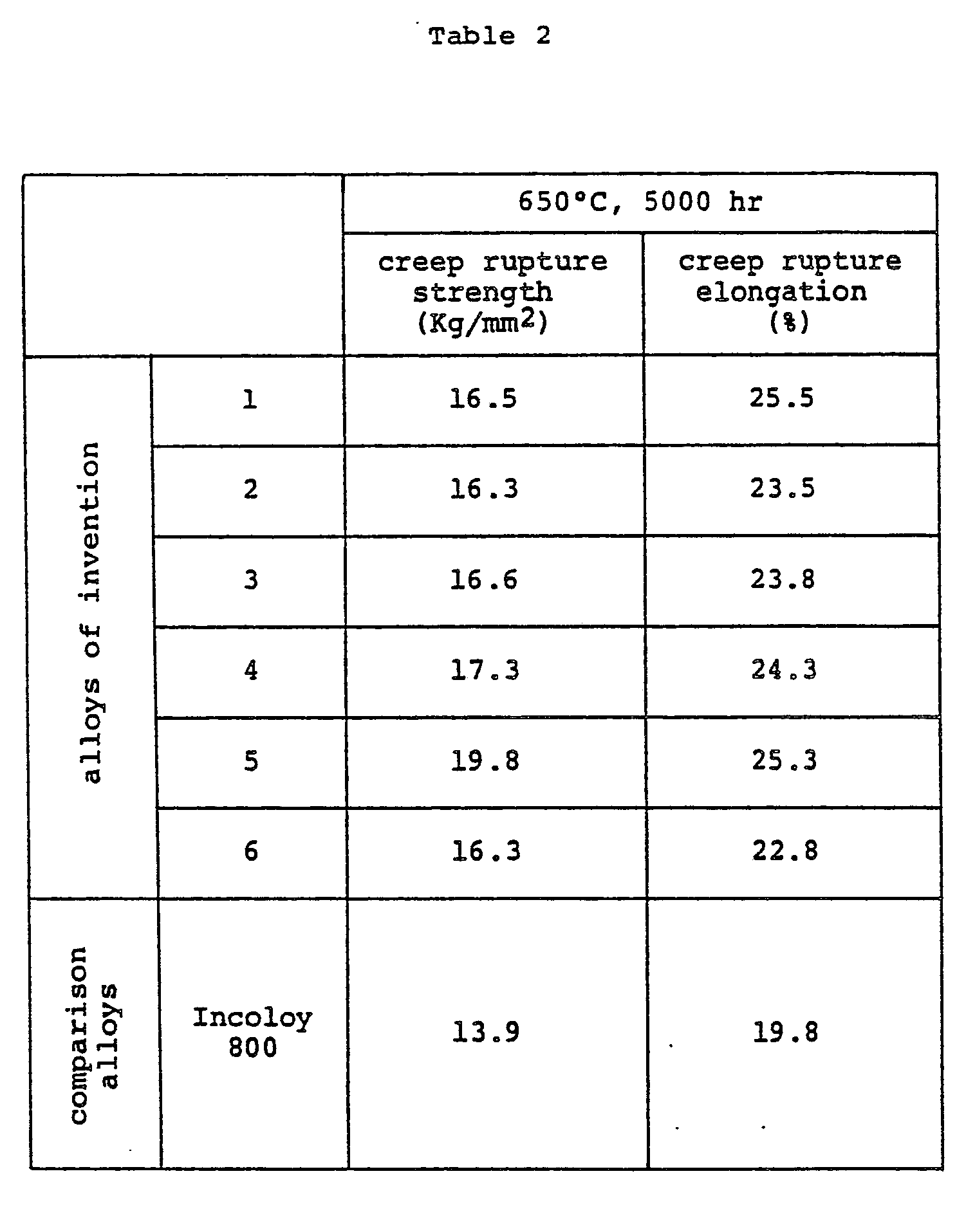
- Table 2 shows the 650°C, 5000-hr creep rupture strength and ductility of the alloys of the invention in comparison with those of the Incoloy 800 which is also an Fe-base alloy. It will be seen from this table that the Incoloy 800 exhibits a creep rupture strength of about 14 Kg/mm 2 and a ductility of 20%, while the alloys of the invention exhibit creep rupture strength ranging between 16 and 20 Kg/mm 2 and ductility ranging between 22 and 26% which are apparently superior to those of the Incoloy 800.
- Table 3 shows the chemical compositions (wt%) of the alloys used as the material of the outer tube.
- the test samples of these alloys for the outer tube were heat-treated, ground and then finished with #800 emery paper before they are subjected to the test.
- the SUS 304, SUS 310 which is 25Cr-20Ni alloy and Inconel 671 which is 50Cr-50Ni alloy were used as the comparison alloys.
- the comparison alloy No. 8 (SUS 304) was subjected to a solid solution treatment consisting of heating at 1050°C for 30 minutes followed by a water cooling, while the comparison alloy No. 18 (SUS 310) was subjected to a solid solution treatment consisting of heating at 1150°C for 30 minutes followed by a water cooling.
- Fig. 3 shows the relationship between the corrosion weight loss and Cr content as observed in a test which was conducted by applying 41%K 2 SO 4 -34% Na 2 SO 4- 25%Fe 2 O 3 to the test pieces and then allowing corrosion of the test pieces by placing them for 100 hours in a gas having a composition corresponding to that of the coal combustion gas: namely, a composition consisting essentially of 1% of S0 2 , 5% of O2, 15% of C0 2 and the balance N 2 (Pt catalyst).
- the alloys of the invention having greater Cr contents than the comparison alloys Nos. 8 and 18 show correspondingly higher corrosion resistances.
- the corrosion resistances of the alloys of the invention well compared with that of the comparison alloy No. 19 (Inconel 671) which has a higher Cr content than the alloys of the Invention. From this fact, it will be understood that the alloys used as the outer tube of the boiler tube of the invention has quite an excellent corrosion resistance.
- Table 4 shows the 750°C, 1000-hr creep rupture strength of the alloys of the invention in comparison with that of the comparison alloy No. 19 (Inconel 671).
- the alloys of the invention exhibit higher creep rupture strengths than the Inconel 671.
- Ni equivalents and Cr equivalents of the alloys Nos. 1 to 7 and 11 to 17 of the invention as shown in Tables 1 and 3, as well as those of the comparison alloys Nos. 8 to 10 and 18 and 19 are plotted in Fig. 1.
- the areas demarcated by broken lines show ranges of Ni equivalent and Cr equivalent of alloys which are preferably be used as the materials of the inner and outer tubes of the double-tube structure of the boiler tube in accordance with the invention.
- a hollow billet of an alloy having a composition same as that of the sample No. 1 shown in Table 1 was prepared as the blank of the inner tube.
- a hollow billet was prepared as the blank of the outer tube, from an alloy having a composition consisting essentially of 0.050% of C, 0.86% of Si, 1.20% of Mn, 40.2% of Ni, 35.1 % of Cr, 1.25% of Mo, 0.42% of Nb and the balance Fe.
- These billets were assembled together to form a double hollow billet, which was hot-rolled by a Mannesmann mill into a double tube blank.
- This blank was then subjected to a cold elongation conducted by a mandrel mill, soft annealing and second cold elongation and made into a tube of a double-wall structure having an outside diameter of 45 mm, inside diameter of 19 mm and a wall thickness of 13 mm (wall thickness of inner tube 10.5 mm, wall thickness of outer tube 2.5 mm).
- the tube was then subjected to a solid solution treatment which was conducted by maintaining the tube at 1170°C for 30 minutes followed by a water cooling to become the final product.
- the alloy of the invention does not cause any cracking in the production of the seamless alloy tube by extrusion or Mannesmann process.
- the present invention provides a boiler tube having a double-tube structure which is superior to conventional ones in both aspects of the corrosion resistance of the outer tube surface which is a matter of significance particularly in boilers using coal as the fuel and the resistance to steam oxidation of the inner tube surface which imposes a problem particularly in boilers which operate at high steam temperature.
- the boiler tube of the invention can suitably be used in the boilers for power generating plants and offers a remarkable improvement in the electric power generating efficiency when applied to such a use.
Landscapes
- Engineering & Computer Science (AREA)
- Metallurgy (AREA)
- Physics & Mathematics (AREA)
- Thermal Sciences (AREA)
- Mechanical Engineering (AREA)
- General Engineering & Computer Science (AREA)
- Rigid Pipes And Flexible Pipes (AREA)
- Feeding And Controlling Fuel (AREA)
Description
- The present invention relates to a boiler tube and, more particularly, to a boiler tube having a double tube structure. The invention also extends to a boiler having at least one such boiler tube.
- Hitherto, in boilers in which the steam temperature in the tube is not higher than 570°C and the temperature of the tube outer wall surface contacting the combustion gas is between 600 and 650°C, low- alloy steels such as 21 Cr-1 Mo steel and 9 Cr-1 Mo steel are generally used as the material of the tubes disposed in the region where the temperature is comparatively low, while austenitic stainless steels such as SUS 304, SUS 321 and SUS 347 are used as the materials of the tubes disposed in the region where the temperature is comparatively high.
- In recent years, to cope with the demand for higher efficiency of electric power generation and so forth, there is a tendency to operate the boilers at a high steam temperature of 600°C and the yet higher temperature of 650°C, and at a correspondingly increased steam pressure. This requires a 30 to 100°C rise of the steam temperature in the boiler tubes and a corresponding rise of the tube outer wall surface temperature. Although austenitic stainless steels are satisfactorily used as the material of the boiler tubes in the region of comparatively high temperature of the boiler when the steam temperature is around 570°C, steam oxidation of the boiler tubes made of austenitic stainless steel is drastically increased and the corrosion of the outer wall surfaces of tubes by the combustion gas is accelerated when the steam temperature is raised to 600°C.
- Under these circumstances, boiler tubes having double tube structure, consisting of an inner tube having a high resistance to steam oxidation and an outer tube having a high resistance to high-temperature corrosion, have been proposed as boiler tubes specifically intended for use at high temperatures. An example of boiler tubes having double-tube structure is shown in JP-A-57-120002.
- In recent years, there is a trend for higher steam temperature also in coal burning boilers which makes use of coal as the fuel. The mechanism of high-temperature corrosion caused by combustion gas is different from that caused by heavy oil combustion gas. Therefore, a material highly resistant to the high-temperature corrosion caused by heavy oil combustion gas does not always exhibit high resistance to the high-temperature corrosion caused by coal combustion gas. Thus, there is an increasing demand for development of boiler tubes which simultaneously meet the requirements for high resistance to steam oxidation, excellent high-temperature strength and high resistance to high-temperature corrosion.
- Accordingly, an object of the invention is to provide a boiler tube which has a high resistance to steam oxidation and an excellent high-temperature strength, as well as a high resistance to corrosion caused by coal combustion gas.
- The invention is set out in
claim 1. - Thus, the invention proposes a boiler tube having a double-tube structure consisting of an inner tube having a high resistance to steam oxidation and an excellent high-temperature strength, and an outer tube having a higher resistance to corrosion than the inner tube.
- Further explanation of the invention follows, and embodiments of the invention will be given by way of non-limitative example, with reference to the accompanying drawings.
- In the drawings:
- Fig. 1 is a diagram showing the relationship between Cr equivalent and Ni equivalent;
- Fig. 2 is a diagram showing the relationship between the thickness of the scale formed on the boiler tube and the heating temperature; and
- Fig. 3 is a diagram showing the relationship between the corrosion weight loss by the high-temperature corrosion and the Cr content of the boiler tube material.
- A description will be made first of the reasons for restricting the content ranges of the constituent elements in the alloy used as the material of the inner tube.
- Incidentally, in this specification percent means percent by weight.
- C: When the C content exceeds 0.02%, C reacts with carbide formers such as Mo, Nb, etc. to form carbides in grains to increase the creep strength at high temperature. On the other hand, C content exceeding 0.15% decreases the corrosion resistance and adversely affects the workability and weldability, due to precipitation of carbides in the grain boundary. For these reasons, the C content is limited to the range between 0.02 and 0.15% and, more preferably, between 0.03 and 0.08%.
- Si: Si remarkably improves the corrosion resistance when its content exceeds 0.5%. However, Si content exceeding 3.5% seriously impairs producibility and workability, making the production of the boiler tube extremely difficult, and unfavourably permits the precipitation of ferrite phase. For these reasons, the Si content is limited to the range between 0.5 and 3.5%. Taking into account the corrosion resistance and workability, the Si content is preferably in the range between 1 and 2%.
- Cr: Cr effectively enhances the resistance to steam oxidation when its content exceeds 20.5% but impairs the high-temperature strength when its content exceeds 27%. The Cr content, therefore, is limited to the range between 20.5 and 27%, more preferably between 22 and 26%.
- Mo: Mo content between 0.5 and 3% effectively strengthens the austenite matrix without adversely affecting the resistance to steam oxidation. In addition, a part of Mo is precipitated in the form of carbides to enhance the high-temperature strength and to strengthen the grain boundary. However, Mo content exceeding 3% allows the formation of ferrite to facilitate the precipitation of sigma phase thereby seriously impairing the workability. For these reasons, the Mo content is limited to the range between 0.5 and 3% and, more preferably, between 1 and 2.5%.
- Nb: Nb precipitates, when its content is not greater than 1%, in the form of carbide to enhance the high-temperature strength and ductility. Particularly, an Nb content between 0.2 and 0.7% is preferred. Further, the ratio Nb/C of the Nb content to C content ranging between 6 and 8 is specifically preferred.
- Ni: Ni co-exists with Cr to increase the plastic workability and to stabilize the austenite structure. To such ends, the Ni content should be not smaller than 25%. However, a Ni content exceeding 40% with the above-specified Cr content undesirably coarsens the columnar crystals to increase the tendency of cracking in the plastic working. For these reasons, the Ni content is limited to the range between 25 and 40% and, more preferably, between 29 and 35%.
- Ti, W: Ti and W are optionally present elements which cause precipitation of carbides in the matrix to increase the ductility at high temperature and to refine the grain size thereby increasing the corrosion resistance. However, when their contents exceed 0.5%, the weldability is impaired to increase the possibility of weld defects. The Ti and W contents, therefore, are limited to be not greater than 0.5% and, more preferably, are between 0.1 and 0.4%.
- B: B content not greater than 0.5% effectively strengthens the grain boundary, increasing ductility at high temperature. The B content is preferably selected in the range between 0.002 and 0.03% in view of the C content because the ratio B/C of the B content to C content not smaller than 0.2 adversely affects the weldability and workability.
- The heat-resisting Fe-base alloy of the invention used as the material of the inner tube corresponds to an alloy wherein Mo, Nb and Si are added to a (20.5-27%) Cr-(25-40%) Ni steel with a view to resistance to steam oxidation, high-temperature strength, ductility and weldability. Particularly, it may correspond to an alloy wherein Ti and AI are eliminated from and Mo, Nb and Si are added to Incoloy 800, which is a heat-resisting Fe-base alloy, with a view to resistance to steam oxidation, weldability, high-temperature strength, ductility and intergranular corrosion resistance. Further, the inner tube is required to have higher resistance to corrosion caused by steam than the conventional boiler tube material such as SUS 304 and SUS 321 having Cr contents of between 18 and 20%. To this end, it is necessary that the Cr content be increased above 20.5%. The Cr solely, however, cannot provide sufficient resistance to corrosion caused by steam of high temperature of between 600 and 650°C, and the addition of not less than 0.5% of Si is essential. Since both of Cr and Si are ferrite formers, the amount of increase in the Cr equivalent due to addition of Si is preferably selected such that the plastic workability is enhanced by reducing the Cr content or increasing the Ni equivalent.
- The increased steam temperature gives rise to a demand for greater high-temperature strength. In the Ni-Cr system alloys, the Ni equivalent andCr equivalent significantly affect the stabilization of the austenite structure and the plastic workability. As shown in Fig. 1, a stable structure is obtained and a good ductility is attained when the Ni equivalent takes a value which is 2 higher than the line which marks the lower limit of the fully austenite region. With the alloy having this structure, it is possible to produce seamless pipes by a plastic working without the fear of cracking.
- The Ni equivalent and the Cr equivalent are given by the following formulae, respectively. The percent in parentheses means the percent by weight.


- In the case of the inner tube, the Cr equivalent and the Ni equivalent are preferably in the ranges between 24 and 33 and between 21 and 38, respectively.
- As mentioned before, the boiler tube of the invention has a double-tube structure having an inner tube and an outer tube having a higher corrosion resistance than the inner tube. Preferably, the outer tube also has an excellent high-temperature strength and high weldability in view of the fact that the outer tube is fixed by welding or the like measure.
- The alloy used as the material of this outer tube preferably has the composition consisting essentially of 0.02 to 0.2% of C, not more than 3.5% of Si, not more than 2% of Mn, 33 to 45% of Ni, 30 to 40% of Cr and the balance Fe. The alloy may additionally contain 0.5 to 3 wt% of Mo and not more than 1 % of Nb. In place of Mo and Nb or in addition to Mo and Ni, it is possible to add not more than 0.5 wt% of W, not more than 0.5 wt% of Ti and not more than 0.03% of B.
- A description will be made hereinunder as to the reasons for restricting the content ranges of the constituent elements in the alloy used as the material of the outer tube.
- C: When the C content is not smaller than 0.02%, C is combined with carbide formers such as Mo, Nb, W and Ti to form carbides in the grains to increase the creep strength at high temperature. However, C content exceeding 0.2% causes a reduction in the precipitation of the carbides in the grain boundary and adversely affects the workability and weldability. From this point of view, the C content is selected preferably to be small. Particularly, the C content between 0.03 and 0.08% is preferred.
- Cr: Cr content not smaller than 30% is quite effective in prevention of corrosion caused at high temperature by the coal combustion gas. The effect of Cr, however, is substantially saturated when the Cr content exceeds 40%. The Cr content, therefore, is limited to the range between 30 and 40% and, more preferably, between 33 and 37%.
- Mo: Mo content of between 0.5 and 3% strengthens the austenite matrix without adversely affecting the resistance to high-temperature corrosion caused by the coal combustion gas. In addition, such Mo content permits precipitation of Mo in the form of carbide in the (30-40%) Cr-(33-45%) Ni steel to effectively raise the high-temperature strength and to strengthen the grain boundary. Thus, the Mo content is limited preferably to the range between 1 and 2%, because Mo content exceeding 3% may adversely affect the workability.
- Nb: Nb is precipitated, when its content is not greater than 1 %, in the form of carbides and effectively increases the ductility as well as the high-temperature strength. Since Nb content exceeding 1% seriously impairs the workability and weldability, the Nb content is limited preferably to the range between 0.1 and 0.5%.
- W, Ti: W and Ti are elements which are precipitated in the matrix in the form of carbides to increase the ductility at high temperature without lowering the corrosion resistance. Taking the weldability into account, however, the W and Ti contents are limited preferably to be not greater than 0.5% and, more preferably, between 0.1 and 0.4%.
- B: B effectively strengthens the grain boundary to improve the ductility at high temperature but does not adversely affect the corrosion resistance. The B content is limited preferably to be not greater than 0.03% and, more preferably, between 0.02 and 0.03%, taking into account the weldability and in view of the C content.
- Ni: Ni coexists with Cr to improve the plastic workability and to stabilize the austenite structure. To this end, the Ni content should be not smaller than 33%. Since the steel used as the material of this outer tube contains 30 to 40% of Cr and ferrite formers such as Mo, Nb and W, it is necessary to effect the control by means of Ni equivalent, in order to maintain a stable austenite phase. The Ni content, however, should not exceed 45% because Ni reacts with S in the coal combustion gas to adversely affect the corrosion resistance.
- In the composition stated above, the alloy used as the material of the outer tube preferably has Cr equivalent and Ni equivalent which range between 36 and 44% and between 35 and 50%, respectively.
- In this alloy used as the material of the outer tube, the corrosion resistance and the high-temperature strength are increased due to the inclusion of amounts of optional amounts of Mo, Nb, W, Ti, B and Si as specified above. However, if ferrite exists in the austenite structure, embrittlement due to precipitation of sigma phase tends to be caused at high temperature. To obviate this problem, it is preferred that the Ni equivalent is at least 2 greater than the line marking the lower limit of the fully austenite region shown in Fig. 1.
- The outer tube having the composition stated hereinbefore provides an excellent high-temperature strength. This in turn permits a reduction in the wall thickness of the inner tube.
- In the boiler tube in accordance with the invention, the inner tube preferably has a wall thickness which is greater than that of the outer tube. The inner tube mainly provides the resistance to steam oxidation and the high-temperature strength, while the outer tube ensures the resistance to corrosion caused by the coal combustion gas. Taking into account the high-temperature strength, the wall thickness of the outer tube is selected preferably in the range between 10 and 30% of that of the inner tube.
- The boiler tube in accordance with the invention is produced by, for example, the following process. As the first step, a hollow billet for outer tube and a hollow billet for inner tube are prepared and assembled together to form a double-tube billet. The double-tube billet is then heated and subjected to a hot extrusion to metallurgically bond the inner tube and the outer tube to each other. Then, the boiler tube blank thus prepared is subjected to cooling, cold elongation by an elongator such as a mandrel mill, heat treatment and cutting to become the final product.
- Table 1 shows the chemical compositions (wt%) of the alloys used as the material of the inner tube in this embodiment. Test samples of these alloys were ground after a heat treatment and were subjected to the test after finishing the surfaces with #800 emery paper. As the heat treatment, the comparison alloys No. 8 and No. 9, which are SUS 304 steel and SUS 321 steel, were subjected to a solid solution treatment consisting of heating at 1050°C for 30 minutes followed by a water cooling. On the other hand, the comparison alloy No. 10 which is Incoloy 800, and the alloys Nos. 1 to 7 in accordance with the invention were subjected to a solid solution treatment consisting of heating at 1150°C for 30 minutes followed by a water cooling.
- Fig. 2 shows the relationship between the steam temperature and the thickness of the scale formed on the alloy sample when the alloy sample is subjected to a 1000-hour corrosion test conducted in the steam of a temperature of between 500 and 700°C. From this Figure, it will be seen that, in the alloy in accordance with the invention, the resistance to steam oxidation is improved as the Si content is increased. In fact, the alloys of the invention exhibit resistance to steam oxidation which is more than about 3 times as high as those of the comparison alloy No. 8 (SUS 304) and the comparison alloy No. 9 (SUS 321). The difference in the resistance to corrosion between the alloys in accordance with the invention and the conventional alloys (comparison alloys Nos. 8 and 9) becomes greater as the temperature becomes higher. It is also understood that the alloys of the invention have corrosion resistances superior to that of the comparison alloy Incoloy 800 (registered trademark) which is also an Fe-base alloy.
- Table 2 shows the 650°C, 5000-hr creep rupture strength and ductility of the alloys of the invention in comparison with those of the Incoloy 800 which is also an Fe-base alloy. It will be seen from this table that the Incoloy 800 exhibits a creep rupture strength of about 14 Kg/mm2 and a ductility of 20%, while the alloys of the invention exhibit creep rupture strength ranging between 16 and 20 Kg/mm2 and ductility ranging between 22 and 26% which are apparently superior to those of the Incoloy 800.
- Table 3 shows the chemical compositions (wt%) of the alloys used as the material of the outer tube. The test samples of these alloys for the outer tube were heat-treated, ground and then finished with #800 emery paper before they are subjected to the test. The SUS 304, SUS 310 which is 25Cr-20Ni alloy and Inconel 671 which is 50Cr-50Ni alloy were used as the comparison alloys. The comparison alloy No. 8 (SUS 304) was subjected to a solid solution treatment consisting of heating at 1050°C for 30 minutes followed by a water cooling, while the comparison alloy No. 18 (SUS 310) was subjected to a solid solution treatment consisting of heating at 1150°C for 30 minutes followed by a water cooling. The solid solution treatment for the comparison alloy No. 19 (Inconel 671, registered trademark) and the alloys of the invention was conducted by heating them at 1200°C for 30 minutes followed by a water cooling.


- The alloys of the invention, having greater Cr contents than the comparison alloys Nos. 8 and 18 show correspondingly higher corrosion resistances. The corrosion resistances of the alloys of the invention well compared with that of the comparison alloy No. 19 (Inconel 671) which has a higher Cr content than the alloys of the Invention. From this fact, it will be understood that the alloys used as the outer tube of the boiler tube of the invention has quite an excellent corrosion resistance.
- Table 4 shows the 750°C, 1000-hr creep rupture strength of the alloys of the invention in comparison with that of the comparison alloy No. 19 (Inconel 671).
- As will be seen from this table, the alloys of the invention exhibit higher creep rupture strengths than the Inconel 671.

- Ni equivalents and Cr equivalents of the alloys Nos. 1 to 7 and 11 to 17 of the invention as shown in Tables 1 and 3, as well as those of the comparison alloys Nos. 8 to 10 and 18 and 19 are plotted in Fig. 1. In this figure, the areas demarcated by broken lines show ranges of Ni equivalent and Cr equivalent of alloys which are preferably be used as the materials of the inner and outer tubes of the double-tube structure of the boiler tube in accordance with the invention.
- A hollow billet of an alloy having a composition same as that of the sample No. 1 shown in Table 1 was prepared as the blank of the inner tube. At the same time, a hollow billet was prepared as the blank of the outer tube, from an alloy having a composition consisting essentially of 0.050% of C, 0.86% of Si, 1.20% of Mn, 40.2% of Ni, 35.1 % of Cr, 1.25% of Mo, 0.42% of Nb and the balance Fe. These billets were assembled together to form a double hollow billet, which was hot-rolled by a Mannesmann mill into a double tube blank. This blank was then subjected to a cold elongation conducted by a mandrel mill, soft annealing and second cold elongation and made into a tube of a double-wall structure having an outside diameter of 45 mm, inside diameter of 19 mm and a wall thickness of 13 mm (wall thickness of inner tube 10.5 mm, wall thickness of outer tube 2.5 mm). The tube was then subjected to a solid solution treatment which was conducted by maintaining the tube at 1170°C for 30 minutes followed by a water cooling to become the final product.
- It will be clear to those skilled in the art that the alloy of the invention does not cause any cracking in the production of the seamless alloy tube by extrusion or Mannesmann process.
- As will be understood from the foregoing description, the present invention provides a boiler tube having a double-tube structure which is superior to conventional ones in both aspects of the corrosion resistance of the outer tube surface which is a matter of significance particularly in boilers using coal as the fuel and the resistance to steam oxidation of the inner tube surface which imposes a problem particularly in boilers which operate at high steam temperature.
- Thus, the boiler tube of the invention can suitably be used in the boilers for power generating plants and offers a remarkable improvement in the electric power generating efficiency when applied to such a use.
Claims (4)
Applications Claiming Priority (2)
| Application Number | Priority Date | Filing Date | Title |
|---|---|---|---|
| JP58050495A JPS59176501A (en) | 1983-03-28 | 1983-03-28 | boiler tube |
| JP50495/83 | 1983-03-28 |
Publications (3)
| Publication Number | Publication Date |
|---|---|
| EP0120704A2 EP0120704A2 (en) | 1984-10-03 |
| EP0120704A3 EP0120704A3 (en) | 1986-07-02 |
| EP0120704B1 true EP0120704B1 (en) | 1989-06-07 |
Family
ID=12860506
Family Applications (1)
| Application Number | Title | Priority Date | Filing Date |
|---|---|---|---|
| EP84302072A Expired EP0120704B1 (en) | 1983-03-28 | 1984-03-27 | Boiler tube |
Country Status (4)
| Country | Link |
|---|---|
| US (1) | US4505232A (en) |
| EP (1) | EP0120704B1 (en) |
| JP (1) | JPS59176501A (en) |
| DE (1) | DE3478634D1 (en) |
Families Citing this family (27)
| Publication number | Priority date | Publication date | Assignee | Title |
|---|---|---|---|---|
| JPS6331535A (en) * | 1986-07-23 | 1988-02-10 | Jgc Corp | Apparatus for treating carbon-containing compound having carbon precipitation suppressing property |
| US4685427A (en) * | 1986-12-08 | 1987-08-11 | Inco Alloys International, Inc. | Alloy for composite tubing in fluidized-bed coal combustor |
| JPH028336A (en) * | 1988-06-28 | 1990-01-11 | Jgc Corp | Carbon deposition-resistant two-layer pipe |
| US4840768A (en) * | 1988-11-14 | 1989-06-20 | The Babcock & Wilcox Company | Austenitic Fe-Cr-Ni alloy designed for oil country tubular products |
| US5050108A (en) * | 1989-11-30 | 1991-09-17 | Aptech Engineering, Inc. | Method for extending the useful life of boiler tubes |
| US5447179A (en) * | 1990-05-18 | 1995-09-05 | Itt Corporation | Non-corrosive double-walled steel tube characterized in that the steel has a face-centered cubic grain structure |
| SE468209B (en) * | 1991-08-21 | 1992-11-23 | Sandvik Ab | APPLICATION OF AN AUSTENITIC CHROME-NICKEL-MOLYBDEN-YEAR ALloy FOR MANUFACTURING COMPODO DRAWERS FOR APPLICATION AS BOTH TUBES IN SODA HOUSES |
| BE1005554A3 (en) * | 1991-12-10 | 1993-10-26 | Bundy Internat Ltd | Method of manufacturing a tube wall multiple. |
| EP0619179A1 (en) * | 1993-04-06 | 1994-10-12 | Nippon Steel Corporation | Wear resisting steel for welded pipes, and manufacturing process |
| JP3222307B2 (en) * | 1994-03-08 | 2001-10-29 | 新日本製鐵株式会社 | Alloy and multi-layer steel pipe having corrosion resistance in an environment in which a fuel containing V, Na, S, Cl is burned |
| JPH08184391A (en) * | 1994-12-29 | 1996-07-16 | Usui Internatl Ind Co Ltd | Bellows pipe |
| US5845837A (en) * | 1995-12-28 | 1998-12-08 | Itt Automotive, Inc. | Polymer-based material for carbon deposition during brazing operations |
| JP3104622B2 (en) * | 1996-07-15 | 2000-10-30 | 住友金属工業株式会社 | Nickel-based alloy with excellent corrosion resistance and workability |
| JP3512304B2 (en) * | 1996-08-15 | 2004-03-29 | 日本冶金工業株式会社 | Austenitic stainless steel |
| US7066973B1 (en) | 1996-08-26 | 2006-06-27 | Nuvera Fuel Cells | Integrated reformer and shift reactor |
| CN1139782C (en) * | 1998-03-27 | 2004-02-25 | 西门子公司 | Heat exchanger tube, method of manufacturing heat exchanger tube, and condenser |
| US6986797B1 (en) | 1999-05-03 | 2006-01-17 | Nuvera Fuel Cells Inc. | Auxiliary reactor for a hydrocarbon reforming system |
| US6641625B1 (en) | 1999-05-03 | 2003-11-04 | Nuvera Fuel Cells, Inc. | Integrated hydrocarbon reforming system and controls |
| CA2349137C (en) * | 2000-06-12 | 2008-01-08 | Daido Tokushuko Kabushiki Kaisha | Multi-layered anti-coking heat resistant metal tube and method for manufacture thereof |
| US20040156737A1 (en) * | 2003-02-06 | 2004-08-12 | Rakowski James M. | Austenitic stainless steels including molybdenum |
| US6352670B1 (en) | 2000-08-18 | 2002-03-05 | Ati Properties, Inc. | Oxidation and corrosion resistant austenitic stainless steel including molybdenum |
| MY138154A (en) * | 2001-10-22 | 2009-04-30 | Shell Int Research | Process to prepare a hydrogen and carbon monoxide containing gas |
| JP2006502938A (en) * | 2002-06-13 | 2006-01-26 | ヌヴェラ フューエル セルズ インコーポレイテッド | Preferential oxidation reactor temperature control |
| US20050058851A1 (en) * | 2003-09-15 | 2005-03-17 | Smith Gaylord D. | Composite tube for ethylene pyrolysis furnace and methods of manufacture and joining same |
| CA2566370C (en) * | 2004-05-20 | 2010-02-09 | Pulp And Paper Research Institute Of Canada | Corrosion-resistant exterior alloy for composite tubes |
| US7985304B2 (en) | 2007-04-19 | 2011-07-26 | Ati Properties, Inc. | Nickel-base alloys and articles made therefrom |
| JP5273266B2 (en) * | 2012-02-08 | 2013-08-28 | 新日鐵住金株式会社 | Double pipe and welded structure using the same |
Family Cites Families (13)
| Publication number | Priority date | Publication date | Assignee | Title |
|---|---|---|---|---|
| US3366473A (en) * | 1965-11-17 | 1968-01-30 | Simonds Saw & Steel Co | High temperature alloy |
| US3859082A (en) * | 1969-07-22 | 1975-01-07 | Armco Steel Corp | Wrought austenitic alloy products |
| US3856516A (en) * | 1970-02-12 | 1974-12-24 | Blair Knox Co | Low creep high strength ferrous alloy |
| BE790297Q (en) * | 1970-07-22 | 1973-02-15 | Pompey Acieries | |
| JPS5347062B2 (en) * | 1974-01-18 | 1978-12-18 | ||
| US4054174A (en) * | 1974-03-18 | 1977-10-18 | The Babcock & Wilcox Company | Method of inhibiting deposition of internal corrosion products in tubes |
| US4026699A (en) * | 1976-02-02 | 1977-05-31 | Huntington Alloys, Inc. | Matrix-stiffened heat and corrosion resistant alloy |
| JPS5662614A (en) * | 1979-10-24 | 1981-05-28 | Usui Internatl Ind Co Ltd | Thick-walled small-diameter superposed metal pipe material |
| JPS5929104B2 (en) * | 1980-05-20 | 1984-07-18 | 愛知製鋼株式会社 | Austenitic heat-resistant steel with excellent hot workability and oxidation resistance |
| JPS57120002A (en) * | 1981-01-19 | 1982-07-26 | Sumitomo Metal Ind | Double tube for boiler |
| JPH0245696B2 (en) * | 1981-12-25 | 1990-10-11 | Hitachi Ltd | SEKITANNENSHOOFUKUMUPURANTOYOBOIRACHUUBU |
| US4489040A (en) * | 1982-04-02 | 1984-12-18 | Cabot Corporation | Corrosion resistant nickel-iron alloy |
| JPS58217662A (en) * | 1982-06-11 | 1983-12-17 | Nippon Steel Corp | High strength and high corrosion resistant boiler tube having resistance against brittlement during use |
-
1983
- 1983-03-28 JP JP58050495A patent/JPS59176501A/en active Granted
-
1984
- 1984-03-27 DE DE8484302072T patent/DE3478634D1/en not_active Expired
- 1984-03-27 EP EP84302072A patent/EP0120704B1/en not_active Expired
- 1984-03-27 US US06/593,931 patent/US4505232A/en not_active Expired - Lifetime
Also Published As
| Publication number | Publication date |
|---|---|
| DE3478634D1 (en) | 1989-07-13 |
| EP0120704A3 (en) | 1986-07-02 |
| JPS59176501A (en) | 1984-10-05 |
| JPH0565762B2 (en) | 1993-09-20 |
| US4505232A (en) | 1985-03-19 |
| EP0120704A2 (en) | 1984-10-03 |
Similar Documents
| Publication | Publication Date | Title |
|---|---|---|
| US4505232A (en) | Boiler tube | |
| EP0819775B1 (en) | A nickel-based alloy excellent in corrosion resistance and workability | |
| GB2122221A (en) | Improvements in and relating to boiler tubes | |
| EP1285097A1 (en) | Martensitic stainless steel and seamless steel pipes produced with it | |
| JP3745567B2 (en) | Boiler steel excellent in ERW weldability and ERW boiler steel pipe using the same | |
| JP3552517B2 (en) | Method for welding high Cr ferritic heat resistant steel and method for manufacturing welded steel pipe | |
| JPS5914097B2 (en) | Ferritic heat-resistant steel with improved toughness | |
| JPH0245696B2 (en) | SEKITANNENSHOOFUKUMUPURANTOYOBOIRACHUUBU | |
| US4141724A (en) | Low-cost, high temperature oxidation-resistant steel | |
| JP4377869B2 (en) | Boiler steel excellent in ERW weldability and ERW boiler steel pipe using the same | |
| JPS62297436A (en) | High-strength ferritic heat-resisting steel for steel tube | |
| JPH0359135B2 (en) | ||
| US3859082A (en) | Wrought austenitic alloy products | |
| JPH1121624A (en) | High strength austenitic heat-resistant steel excellent in weldability and method for producing the same | |
| JPH02203092A (en) | Double layer steel pipe having corrosion resistance in environment burning fuel containing v, na, s, cl | |
| JP2002363709A (en) | High Cr ferritic heat resistant steel | |
| JP2575250B2 (en) | Line pipe with excellent corrosion resistance and weldability | |
| JPH02156049A (en) | Heat resisting steel for ethylene decomposition furnace tube | |
| JP7538401B2 (en) | Low alloy heat resistant steel | |
| JPH0117042B2 (en) | ||
| JPH11335786A (en) | Clad steel pipe | |
| JPH0218380B2 (en) | ||
| JP3529701B2 (en) | Martensitic stainless steel for large diameter seamless steel pipes | |
| JPH1046290A (en) | Boiler steel and seamless steel pipe for boilers with excellent hot workability and creep resistance | |
| JPH09296249A (en) | Cr-Mo steel |
Legal Events
| Date | Code | Title | Description |
|---|---|---|---|
| PUAI | Public reference made under article 153(3) epc to a published international application that has entered the european phase |
Free format text: ORIGINAL CODE: 0009012 |
|
| 17P | Request for examination filed |
Effective date: 19840515 |
|
| AK | Designated contracting states |
Designated state(s): DE FR GB IT |
|
| PUAL | Search report despatched |
Free format text: ORIGINAL CODE: 0009013 |
|
| AK | Designated contracting states |
Kind code of ref document: A3 Designated state(s): DE FR GB IT |
|
| 17Q | First examination report despatched |
Effective date: 19871207 |
|
| GRAA | (expected) grant |
Free format text: ORIGINAL CODE: 0009210 |
|
| AK | Designated contracting states |
Kind code of ref document: B1 Designated state(s): DE FR GB IT |
|
| REF | Corresponds to: |
Ref document number: 3478634 Country of ref document: DE Date of ref document: 19890713 |
|
| ET | Fr: translation filed | ||
| ITF | It: translation for a ep patent filed | ||
| ITTA | It: last paid annual fee | ||
| PLBE | No opposition filed within time limit |
Free format text: ORIGINAL CODE: 0009261 |
|
| STAA | Information on the status of an ep patent application or granted ep patent |
Free format text: STATUS: NO OPPOSITION FILED WITHIN TIME LIMIT |
|
| 26N | No opposition filed | ||
| PGFP | Annual fee paid to national office [announced via postgrant information from national office to epo] |
Ref country code: FR Payment date: 19980116 Year of fee payment: 15 |
|
| PG25 | Lapsed in a contracting state [announced via postgrant information from national office to epo] |
Ref country code: FR Free format text: LAPSE BECAUSE OF NON-PAYMENT OF DUE FEES Effective date: 19991130 |
|
| REG | Reference to a national code |
Ref country code: FR Ref legal event code: ST |
|
| REG | Reference to a national code |
Ref country code: GB Ref legal event code: IF02 |
|
| PGFP | Annual fee paid to national office [announced via postgrant information from national office to epo] |
Ref country code: GB Payment date: 20020315 Year of fee payment: 19 |
|
| PGFP | Annual fee paid to national office [announced via postgrant information from national office to epo] |
Ref country code: DE Payment date: 20020528 Year of fee payment: 19 |
|
| PG25 | Lapsed in a contracting state [announced via postgrant information from national office to epo] |
Ref country code: GB Free format text: LAPSE BECAUSE OF NON-PAYMENT OF DUE FEES Effective date: 20030327 |
|
| PG25 | Lapsed in a contracting state [announced via postgrant information from national office to epo] |
Ref country code: DE Free format text: LAPSE BECAUSE OF NON-PAYMENT OF DUE FEES Effective date: 20031001 |
|
| GBPC | Gb: european patent ceased through non-payment of renewal fee |
Effective date: 20030327 |